Table of Contents
Advertisement
Instructions
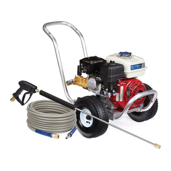
AquaMax Pressure Washers
IMPORTANT SAFETY INSTRUCTIONS
Read all warnings and instructions in this manual.
SAVE THESE INSTRUCTIONS.
-For high pressure water cleaning-
-For outdoor use only-
Model
Horse Power and
Motor Brand
2525DD
160cc Honda
2730DD
200cc Honda
3030DD
270cc Honda
3540DD
390cc Honda
4043BD
480cc Vanguard
PROVEN QUALITY. LEADING TECHNOLOGY.
Maximum Working
Pressure
PSI
MPa
bar
2500 17.24 172.4
2700 18.62 186.2
3000 20.68 206.8
3500 24.13 241.3
4000
27.6
276
3A0679D
EN
37-1110 012113
Advertisement
Table of Contents

Related Manuals for Graco 2525DD


Summary of Contents for Graco 2525DD
- Page 1 IMPORTANT SAFETY INSTRUCTIONS Read all warnings and instructions in this manual. SAVE THESE INSTRUCTIONS. Model Horse Power and Maximum Working Motor Brand Pressure 2525DD 160cc Honda 2500 17.24 172.4 2730DD 200cc Honda 2700 18.62 186.2 3030DD 270cc Honda 3000 20.68 206.8...
-
Page 2: Table Of Contents
Pre-Start Inspection Procedures ........11 Pump Assembly - Parts - Series A ......24 Operating Instructions ..........12 24E735 (For Use With Model 2525DD) ......24 Priming The Pump ............12 Pump Assembly - Parts- Series B ......26 Start-Up ................. 13 24R713 (For Use With Model 2525DD) ...... -
Page 3: Important User Information
The following warnings are for the setup, use, grounding, maintenance, and repair of this equipment. The exclamation point symbol alerts you to a general warning and the hazard symbols refer to procedure-spe- cific risks. When these symbols appear in the body of this manual, refer back to these Warnings. Product- specific hazard symbols and warnings not covered in this section may appear throughout the body of this manual where applicable. -
Page 4: Fire & Ventilation Precautions
WARNING • Do not direct spray on or into electrical installations of any kind! This includes electrical outlets, light bulbs, fuse boxes, transformers, etc. Severe electrical shock may occur. • Even after you shut off the unit, there is high pressure water left in the pump, hose and gun until you release it by triggering the gun. -
Page 5: Miscellaneous Safety Precautions
WARNING MISCELLANEOUS SAFETY PRECAUTIONS Never allow children or adolescents to operate this unit. Read and follow all handling, operations, maintenance and safety instructions listed in this manual and the engine operator’s manual that accompanies this unit, and provide such information to anyone who will be operating this unit. -
Page 6: Component Identification - Direct Drive Models
Component Identification – Direct Drive Models Item Description Detergent Strainer Detergent Hose Water Inlet Water Inlet Quick Connect Adapter Water Outlet Decal - Warning/Caution/Operation Oil Sight Glass Pump Adjustable Unloader Knob Decal - Caution: Risk Of Fire Decal - Warning: Risk Of Burns Engine Pressure Gauge Thermal Relief Valve... -
Page 7: Component Identification - Belt Driven Models
Component Identification – Belt Driven Models Item Description Thermal Relief Valve Water Outlet Decal - Warning: Risk Of Burns Water Inlet Engine Water Inlet Quick Connect Adapter Decal - Caution: Risk Of Fire Battery Box Oil Sight Glass Detergent Strainer Decal - Warning/Caution Detergent Hose Beltguard... -
Page 8: Installation & Preparation Instructions
INSTALLATION & PREPARATION INSTRUCTIONS Do not allow the unit to be exposed to rain, snow or Attire freezing temperatures. If any part of the unit becomes frozen, excessive pressure may build up in the unit which could cause it to burst resulting in possible seri- ous injury to the operator or bystanders. -
Page 9: Engine Fuel Tank
INSTALLATION & PREPARATION The 0° nozzle (RED): This is a blasting nozzle. It deliv- ers a very concentrated stream of water. Be cautious INSTRUCTIONS when using the straight narrow stream. It is not recom- mended for use on painted or wood surfaces, or items Engine Fuel Tank attached with adhesive backings. -
Page 10: Nozzle Connection
INSTALLATION & PREPARATION 1. Using a screw driver, remove the screen from the water inlet. INSTRUCTIONS 2. Clean or replace if necessary. Connect the hoses. 1. Connect one end of the water supply hose to the water inlet of the unit. Nozzle Connection 2. -
Page 11: Unloader
NOTICE unit. If you require service, contact Graco Customer Do not overtighten the unloader. Breakage could Service. result in immediate loss of water pressure and... -
Page 12: Operating Instructions
OPERATING INSTRUCTIONS NOTICE Be certain the nozzle is not connected to the unit Priming the Pump while priming the pump. Priming allows mineral de- It is essential to prime the pump on initial start-up and posits to be released from the system which would obstruct or damage the nozzle assembly resulting in each time the water supply is disconnected from the unit after initial use. -
Page 13: Start-Up
If you require Locate the Safety Decals on your unit and heed their service, contact Graco Customer Service. warnings. 6. Trigger the gun several times. Be certain to lock the Never look directly into the nozzle. -
Page 14: Cleaning With Detergents
OPERATING INSTRUCTIONS 3. To apply solution; unlock the trigger gun and squeeze the trigger. In a few moments a detergent/water mixture will exit the low pressure nozzle. Start spraying the Cleaning with Detergents lower portion of the surface being cleaned and move up, using long overlapping strokes. -
Page 15: Storage & Maintenance Instructions
STORAGE & MAINTENANCE Quick Couplers INSTRUCTIONS There is an o-ring seal inside the female quick coupler. This o-ring will deteriorate or, if the unit is allowed to pump without the high pressure hose or nozzle at- Engine tached, the o-ring may be blown out occasionally. The engine instructions that accompany your unit detail Simply insert a replacement o-ring to correct the leak. -
Page 16: Winterizing
2. Relieve system pressure by pointing the trigger gun in • Two 5 gallon containers. a safe direction and squeezing the trigger until water • One gallon of antifreeze. (Graco® recommends an flow ceases to exit the nozzle. environmentally safe antifreeze.) 3. -
Page 17: Troubleshooting
Troubleshooting Problem Cause Solution Engine will not start. Various engine problems. Refer to the engine manual accom- panying your unit. Unit components are frozen. Allow to thaw. If any part of the unit becomes frozen; excessive pres- sure may build up in the unit which could cause the unit to burst result- ing in possible serious injury to the operator or bystanders. -
Page 18: Pump Service: 2525 Model Pressure Washers
PUMP SERVICE: 2525 MODEL Servicing V-Packings PRESSURE WASHERS 1. Remove manifold as described in Valve Replacement Section. 2. Remove white retaining ring, this may be stuck on the Repair kits are available. See the Parts List, page 24. piston. For the best results, use all parts in kits. 3. -
Page 19: Pump Service: 2730 Model Pressure Washers
PUMP SERVICE: 2730 MODEL replaced) on plunger shaft. Then install plunger. 6. Lightly grease the retaining screw and outer end of the PRESSURE WASHERS plunger. Place washer, o-ring and backup ring around screw and install nut through plunger. Torque to 11.0 Repair kits are available. -
Page 20: Pump Service: 3030 And 3540 Model Pressure Washers
PUMP SERVICE: 3030 AND 3540 plunger. Place washer, o-ring and backup ring around screw and install nut through plunger. Torque to 11.0 MODEL PRESSURE WASHERS ft-lb (15 Nm). Note: If replacing packings, see Servicing V-Packings. Repair kits are available. See the Parts List, page 32, 7. -
Page 21: Pump Service: 4043 Model Pressure Washers
PUMP SERVICE: 4043 MODEL the plunger. 6. Lightly grease the retaining screw and outer end of the PRESSURE WASHERS plunger. Place washer, o-ring and backup ring around screw and install nut through plunger. Torque to 14.7 Repair kits are available. See the Parts List, page 22. ft-lb (20 Nm). -
Page 22: Pressure Washer - Parts
Pressure Washer - Parts 262316- Model 2525DD... - Page 23 22 BOLT 802127 NOZZLE, 40° 805538 23 WASHER 107194 NOZZLE, DETERGENT 805634 24p DECAL - RISK OF FIRE DECAL - AQUAMAX 2525DD 16E232 25p DECAL - RISK OF BURNS BASEPLATE 16E506 26 ENGINE 16E657 DECAL- SILVER STICKER 27 KEY 197792...
-
Page 24: Pump Assembly - Parts - Series A
Pump Assembly - Parts - Series A 24E735 (for use with Model 2525DD) - Page 25 Pump Assembly - Parts 24E735 (for use with Model 2525DD) DESCRIPTION PART # QTY KIT, REPAIR, VALVES 24E736 INCLUDES 1 KIT, REPAIR, PLUNGER 24E737 INCLUDES 2 KIT, REPAIR, OIL SEAL 24E738 INCLUDES 3 KIT, REPAIR, UNLOADER 24E739 INCLUDES 4 KIT, REPAIR, PACKINGS...
-
Page 26: Pump Assembly - Parts- Series B
Pump Assembly - Parts - Series B 24R713 (for use with Model 2525DD) - Page 27 Pump Assembly - Parts 24R713 (for use with Model 2525DD) DESCRIPTION PART # QTY KIT, REPAIR, VALVES 24R715 INCLUDES 1 THERMAL RELIEF VALVE 117759 INCLUDES 2 FILTER, INLET 801112 INCLUDES 3 KIT, REPAIR, PACKINGS 24R718 INCLUDES 4 KIT, REPAIR, OIL SEAL...
-
Page 28: Pressure Washer - Parts
Pressure Washer - Parts 262318- Model 2730DD... - Page 29 Pressure Washer - Parts 262318- Model 2730DD DESCRIPTION PART# DESCRIPTION PART# GROMMET 16E489 25 CHEMICAL HOSE 117760 NOZZLE, 0° 805535 26 HOSE NOZZLE, 15° 805536 27 STRAINER NOZZLE, 25° 805537 28 KEY 197792 NOZZLE, 40° 805538 29 HEAT DUMP VALVE 116461 NOZZLE DETERGENT 805634...
-
Page 30: Pump Assembly - Parts
Pump Assembly - Parts 244749 (for use with Model 2730DD) - Page 31 Pump Assembly - Parts 244749 (for use with Model 2730DD) DESCRIPTION PART # KIT, REPAIR, VALVES 804402 INCLUDES 24 KIT, REPAIR, OIL SEAL 804033 INCLUDES 36 KIT, REPAIR, PLUNGER 804011 INCLUDES 37 KIT, REPAIR, PACKINGS 804037 INCLUDES 32, 33, 34, 35 KIT, REPAIR, CHEMICAL INJECTOR 24E748 INCLUDES 25-31...
-
Page 32: Pressure Washer - Parts
Pressure Washer - Parts 262320- Model 3030DD 262322- Model 3540DD... - Page 33 Pressure Washer - Parts 262320- Model 3030DD 262322- Model 3540DD DESCRIPTION PART # DESCRIPTION PART # GROMMET 16E489 23 BOLT 111803 NOZZLE (3030DD) 0° 805539 24 WASHER 100731 NOZZLE (3030DD) 15° 805540 25 LOCKNUT 101566 NOZZLE (3030DD) 25° 805541 26 ENGINE (3030DD) 16E659 NOZZLE (3030DD) 40°...
-
Page 34: Pump Assembly - Parts
Pump Assembly - Parts 24E753 (for use with Model 3030DD) 24E750 (for use with Model 3540DD) - Page 35 Pump Assembly - Parts 24E753 (for use with Model 3030DD) 24E750 (for use with Model 3540DD) DESCRIPTION PART # KIT, REPAIR, VALVES 804402 INCLUDES 10 KIT, REPAIR, OIL SEAL 24E744 INCLUDES 18 KIT, PLUNGER 24E745 INCLUDES 22 KIT, REPAIR, PACKINGS 24E746 INCLUDES 11-17 KIT, REPAIR, PLUNGER...
-
Page 36: Pressure Washer - Parts
Pressure Washer - Parts 262326- Model 4043BD... - Page 37 Pressure Washer - Parts 262326- Model 4043BD DESCRIPTION PART# DESCRIPTION PART# HANDLE 16E514 48 HEAT DUMP VALVE 116460 WASHER 107194 49 NIPPLE 156849 LOCKNUT 111040 50 HOSE BARB 16E482 BOLT 114251 51 HOSE CLAMP 16E502 WHEEL 16E474 52 HOSE 16J761 LOCKNUT 119554 53 BRACKET...
-
Page 38: Pump Assembly - Parts
Pump Assembly - Parts 803508 (for use with Model 4043BD) - Page 39 Pump Assembly - Parts 803508 (for use with Model 4043BD) DESCRIPTION PART# KIT, REPAIR, VALVES 801472 INCLUDES 1 KIT, REPAIR, OIL SEAL 801473 INCLUDES 9 KIT, PLUNGER 803502 INCLUDES 10 KIT, REPAIR, PLUNGER 803510 INCLUDES 11, 12, 13 KIT, REPAIR, PACKINGS ONLY 803511 INCLUDES 3, 4, 6 KIT, REPAIR, PACKING ASSY...
-
Page 40: Notes
Notes... -
Page 41: Technical Data
Technical Data Model 2525DD Model 2730DD Model 3030DD Model 3540DD Model 4043BD Working Pressure 2250-2300 psi 2600-2700 psi 2800-2900 psi 3400-3500 psi 3900-4000 psi Range Operating Pressure 2275 psi 2650 PSI 2850 PSI 3450 psi 4000 psi Maximum Working 2500 psi... -
Page 42: Graco Standard Warranty
Graco, Graco will, for a period of twelve months from the date of sale, repair or replace any part of the equipment determined by Graco to be defective. This warranty applies only when the equipment is installed, operated and maintained in accordance with Graco’s written...
Need help?
Do you have a question about the 2525DD and is the answer not in the manual?
Questions and answers