
Related Manuals for Phoenix Model GENESIS


Summary of Contents for Phoenix Model GENESIS
-
Page 1: Instruction Manual
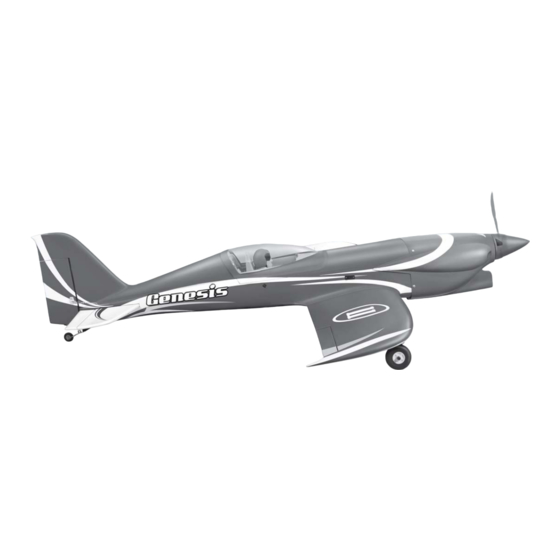
Instruction Manual Wingspan: 1530mm (60.24 inches) Length : 1310mm (51.57 inches) Weight : 2700g - 2900g Engine : 46-55 two stroke / 52 four stroke Radio : 6 channel / 6 servo... -
Page 2: Kit Contents
KIT CONTENTS: We have organized the parts as they come out of the box for better identification during assembly. We recommend that you regroup the parts in the same manner. This will ensure you have all of parts required before you begin assembly KIT CONTENTS AIR FRAME ASSEMBLIES AILERON CONTROL SYSTEM... -
Page 3: Tools And Supplies Needed
Please trial fit all the parts. Make sure you have the correct parts and that they fit and are aligned properly before gluing! This will assure proper assembly. The TEMPORARY PIN GENESIS is hand made from natural materials, TO KEEP HINGE every plane is unique and minor adjustments may CENTERED have to be made. -
Page 4: Installing The Aileron Servos
INSTALLING THE AILERON SERVOS 5. Place the aileron servo tray / hatch into the servo box on the bottom of the wing and drill 1. Install the rubber grommets and brass eyelets 1,6mm pilot holes through the tray and the onto the aileron servo. -
Page 5: Installing The Aileron Linkages
3. Repeat step # 1 - # 2 to install the control horn 8. Insert the 90 degree bend down through the on the opposite aileron. hole in the servo arm. Install one nylon snap keeper over the wire to secure it to the arm. Install the servo arm retaining screw and remove the masking tape from the aileron. - Page 6 3. Glue the plastic part by C.A glue. Aluminum collar 7. Secure the wheel. 4. Attach the metal rod to the retract gear. Metal pushrod Clevis 5. Install and secure the retract gear into the wing. 6. Secure the wooden plate. Machine screw 8.
-
Page 7: Installing The Horizontal Stabilizer
Cowl (head) 9. Slide both wing to the fuselage, attach both metal pushrod to the servo arm of the servo retract gear. Retract and the gear is closed. INSTALLING THE HORIZONTAL STABILIZER 1. Using a modeling knife, cut away the covering from the fuselage for the stabilizer and remove it. - Page 8 6. Attach the wing to the fuselage as picture. Plastic screw 4. With the horizontal stabilizer correctly aligned, mark the shape of the fuselage onto the bottom and into the top of the horizontal stabilizer 7. Test the position of the elevator and adjust it as using a water soluble/ non-permanent felt-tip shown.
-
Page 9: Installing The Vertical Stabilizer
9. After the epoxy has fully cured, remove the masking tape or T-pins used to hold the stabilizer in place and carefully inspect the glue joints. Use more epoxy to fill in any gaps that were not filled previously and clean up the excess using a paper towel and rubbing alcohol. -
Page 10: Installing The Engine
2. Set the tail wheel assembly in place on the INSTALLING THE THROTTLE PUSHROD HOUSING plywood plate. 1. Place the engine into the engine mount and 3. Drill 2,6mm pilot holes through the plywood align it properly with the front of the cowling. plate. - Page 11 5. Test fit the stopper assembly into the tank. It may be necessary to remove some of the flashing around the tank opening using a modeling knife. If flashing is present, make sure none of it falls into the tank. 6.
-
Page 12: Installing The Elevator Pushrod
SERVO INSTALLATION INSTALLING THE FUSELAGE SERVOS 1. Install the rubber grommets and brass collets into the elevator, rudder and throttle servos. Test fit the servos into the servo tray. Trim the tray if necessary to fit your servos 2. Mount the servos to the tray using the mounting Control horn elevator screws provided with your radio system. -
Page 13: Installing The Rudder Pushrod
8. Locate one nylon servo arm, and using wire cutters, remove all but one of the arms using a 2mm drill bit, enlarge the third hole out from the center to accommodate the rudder pushrod Metal domino wire. 9. Plug the rudder servo into the receiver and center the servo. -
Page 14: Mounting The Cowl
4. Manually push the carburator barrel fully closed. 6. Slide the cowl back over the engine and secure Angle the arm back about 45 degree from it in place using four 3mm x 12mm wood center and attach the servo arm onto the servo. screws. -
Page 15: Installing The Switch
3. Position the battery pack and receiver behind BALANCING the fuel tank. Use the two light plywood pieces, placed over the battery and receiver and glue 1. It is critical that your airplane be balanced to the fuselage sides to hold the battery and correctly. -
Page 16: Control Throws
CONTROL THROWS 1. We highly recommend setting up a plane using the control throws listed. 2. The control throws should be measured at the widest point of each control surface. 3. Check to be sure the control surfaces move in the correct directions. - Page 17 I/C FLIGHT GUIDELINES Operate the control sticks on the When ready to fly, first extend the transmitter and check that the control transmitter aerial. surfaces move freely and in the ALWAYS land the model INTO the CORRECT directions. wind, this ensures that the model lands at the slowest possible speed.
Need help?
Do you have a question about the GENESIS and is the answer not in the manual?
Questions and answers