FULTON J Series Installation, Operation And Maintenance Manual
Dual fuel steam boiler, switchable burner, including optional fully modulating burner
Hide thumbs
Also See for J Series:
Table of Contents
Advertisement
Advertisement
Table of Contents

Related Manuals for FULTON J Series


Summary of Contents for FULTON J Series
- Page 1 Fulton Ltd INSTALLATION, OPERATION AND MAINTENANCE MANUAL J SERIES - DUAL FUEL STEAM BOILER (Switchable Burner) (including optional Fully Modulating Burner) This manual must be available to the boiler operator at all times. J DUAL FUEL MANUAL 02 2014 ISSUE 9...
- Page 2 The Pressure System Safety Regulations 2000 Fulton boilers fall within the scope of the Pressure Systems Examination Scheme. Regular inspections are therefore required by a competent person. The scope of the examination and the actual intervals between examinations is at the discretion of the competent person.
-
Page 3: Table Of Contents
LIST OF CONTENTS INTRODUCTION MAINTENANCE General Visual Checks Technical Data Water Level and Low Water Safety Controls - Pump Test 4.2.1 INSTALLATION - 1st Low Water Level Check 4.2.2 - 2nd Low Water Level Check 4.2.3 General Main Blowdown Siting Water Column Blowdown Ventilation Water Level Gauge Blowdown... - Page 4 Obtain a service manual from may cause serious burns. Only competent and qualified Fulton Ltd or call a Fulton service engineer. personnel should work on or in the locality of a steam boiler and ancillary equipment. Always ensure the working area and...
- Page 5 LIST OF ILLUSTRATIONS TITLE FIG. NO Typical Dual Fuel Boiler Major Fuel Components Typical Installation Boiler Flue Connection Boiler Feed Water Arrangement Boiler Blowdown (20-60) Boiler Blowdown (6-15) Boiler Top Components Control Box Gas Supply Oil Supply Steam Pressure Gauge Basic Burner Electrode Settings Feedewater Stop Valve Ignition Flame Detector...
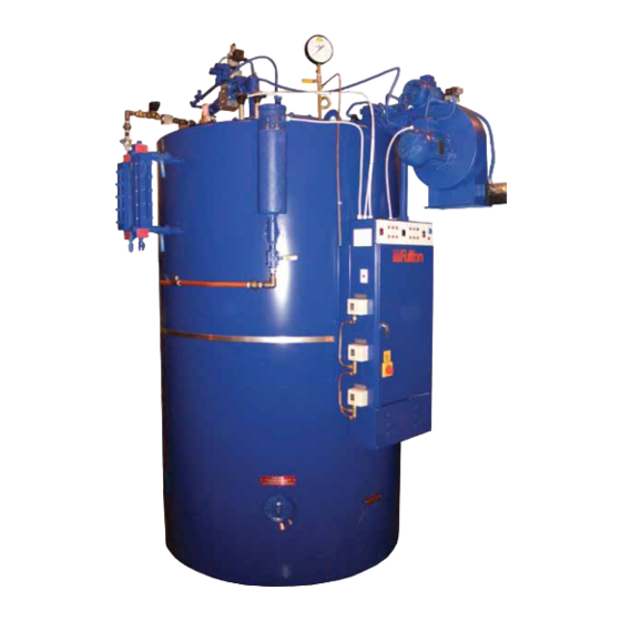
- Page 6 Monobloc Gas Steam Pressure Oil Pump Motor Train Gauge Water Column Automatic TDS Blowdown Air Pressure Switch Motorised Water Level High / Low Gauge Sets Control Operator Control Panel Control Box Fuel Selector Switch Door Electrical Isolator Steam Pressure Controllers FIG.
-
Page 7: Introduction
SECTION 1 - INTRODUCTION GENERAL The Fulton J Series Dual Fuel Fired Steam Boiler is a vertical two-pass boiler of simple and efficient design and construction. Every care has been taken in the manufacture of the boiler to ensure that quality and reliability standards are maintained. - Page 8 Oil Feed Solenoid Oil Feed Valves Lines Oil Pump Motorised High / Low Control Monobloc Gas Steam Outlet Feedwater Valve Inlet Pressure Gauge Oil Solenoid Gas Inlet Valves Oil Pump Safety Valve Motor Water Level Water Column Water Level Gauge Sight Limiters Glass Water Level Probes...
-
Page 9: Installation
SECTION 2 - INSTALLATION GENERAL The installation of a J Series Dual Fuel Fired Steam Boiler should be carried out by competent personnel in accordance with all relevant safety regulations. It is the responsibility of the installer to ensure that these regulations are complied with. - Page 10 FIG. 3 TYPICAL INSTALLATION Page 10 J DUAL FUEL MANUAL 02 2014 ISSUE 9...
-
Page 11: Flue Outlet
FLUE OUTLET The boiler is supplied with a stainless steel flue spigot that should be inserted into the flue outlet in the back of the boiler and secured with the three angle clips supplied loose in the trim box. The height and type of flue will generally be subject to local planning regulations and approvals. The following information is intended to provide assistance where the installation of a simple flue is required. -
Page 12: Water Supply (See Also Section 5.3)
If the boiler is to be operated with little or no condensate return, consideration should be given to pre-heating the feedwater. If in doubt consult Fulton Ltd. The feedwater inlet connection on some boilers is located on the left hand side of the boiler below the sight glass assembly. -
Page 13: Blowdown Valves
All of these valves must be connected to a blowdown receptacle of approved design. Regulations exist covering such items and care must be taken to ensure compliance with these regulations. If in doubt regarding blowdown arrangements, consult Fulton Ltd. FIG. 6 BOILER BLOWDOWN (models 20-60) FIG. - Page 14 Flame detector Electrical Ignition Oil supply location connection box transformer Adjustable Oil pump Oil supply air control valves Ignition Secondary air electrodes damper Steam supply Safety valve Burner assembly Flame detector Oil supply connections pipe Water level Ignition electrodes probes FIG.
-
Page 15: Main Steam Valve
MAIN STEAM VALVE The main steam stop valve should be inserted in the steam line approximately 305mm from the top of the boiler. STEAM SAFETY VALVES Safety valves are factory fitted and preset, they MUST NOT be adjusted. The discharge outlet should be piped to a safe discharge point and the piping so arranged that any condensate trapped in the pipework will drain away from the valve. -
Page 16: Gas Supply
2.11 GAS SUPPLY Verify that the burner is suitable for the type of gas being supplied. Ensure that the piping from the meter is the correct size, and that a gas cock is inserted in the line between the boiler and the meter. To avoid pressure drops, eliminate all unnecessary bends and elbows in the pipework between the gas meter and the boiler. -
Page 17: Oil Supply
2.12 OIL SUPPLY The positioning of the oil storage tank will be dependent on site conditions and local regulations. The burner fuel pump is of the bypass type requiring the installation of feed and return lines between the oil storage tank and the boiler. These lines should be in tubing of a minimum bore of 10 mm. A fire valve, stop valve and check valves should be inserted in the oil feed line. -
Page 18: Steam Pressure Gauge
2.13 STEAM PRESSURE GAUGE The steam pressure gauge assembly should be assembled in accordance with Fig. 11 using a suitable sealant on all joints. The gauge should be facing front towards the electrical control box and/or the operator of the boiler. Screw the assembly into the top of the boiler and connect the copper tube from the pressure controller located on the side of the control box to the nipple provided on the assembly. -
Page 19: Commissioning The Boiler
It is essential that the commissioning procedures listed below are carried out by a Fulton Service Engineer who will have the necessary experience and testing equipment to ensure that the installation is not only correct, but is operating safely and at optimum efficiency. - Page 20 Burner Plate NOTES: 1. GAS ELECTRODE TIP SHOULD BE POSITIONED 3mm FROM THE END OF THE GAS SUPPLY PIPE TO ENABLE IGNITION. 2. OIL ELECTRODE TIP SHOULD BE 271.5 POSITIONED 3mm FROM ONE OF THE OIL NOZZLES. Oil Ignition Gas Ignition Electrode Electrodes dimensions in mm...
-
Page 21: Boiler Inspection And Initial Firing Oil
2.14.1 BOILER INSPECTION AND INITIAL FIRING Ensure the boiler has been washed out after installation. It is advisble to conduct a water analysis before operating the boiler. Examine the probes in the water column and the boiler shell. Replace any damaged probes. 2. - Page 22 11. Observe the flame through the peephole between the electrodes and adjust the primary air control so that the flame cannot be seen 'backing up' the blast tube. 12. Observe the flame through the eye glass in the burner plate. The desired flame shape is a full swirling flame brushing the wall of the furnace.
-
Page 23: Boiler Inspection And Initial Firing Gas
2.14.2 BOILER INSPECTION AND INITIAL FIRING The commissioning procedures listed below must be carried out by a Fulton service engineer who will have the necessary experience and testing equipment to ensure that the installation is not only correct, but is operating at maximum efficiency. -
Page 24: Gas Monoblocs (Non Modulating Burners)
If the pressure control is fitted with a differential scale: (see OEM literature in Section 5) 1. Set the main scale pressure to the maximum pressure required (system pressure). Do not exceed the boiler operating pressure. 2. Set the differential scale to it’s minimum pressure. -
Page 25: Multibloc Gas Valve (Non Modulating Burners)
2.15.1 MULTIBLOC GAS VALVES 6J - 30J MODELS (NON MODULATING BURNER) (see attached manufacturers leaflets). Output pressure controller adjusting screw Hydraulic Brake Operating indicator Main gas flow adjustment Adjustable pressure switch Test point Test point connection connection downstream of Valve 1 Gas output flange Test point connection... - Page 26 Hydraulic brake Main gas flow adjustment Solenoid Low fire adjustment ring Test point connection downstream of valve 1 Test point connection down stream of valve 2 Test point connection upstream of valve 1 SETTING THE BURNER FOR LOW FIRE / HIGH FIRE, Models 40J, 50J AND 60J (Non Modulating Burner) The correct settings for low fire/high fire operation are obtained by making adjustments to the two stage Multibloc valve and the high/low fire steam pressure control.
-
Page 27: Multibloc Gas Valve (Fully Modulating Burner)
2.15.2 MULTIBLOC GAS VALVES 30J - 60J MODELS (FULLY MODULATING BURNER) GAS ACTUATOR Servo motor body Valve coupling GAS GOVERNOR & VALVE Gas valve Gas governor Filter & main Electrical housing connections Gas in flange Gas out flange Low gas pressure switch Filter caps FIG. -
Page 28: Setting The Burner Controls For
2.16 SETTING THE BURNER CONTROLS FOR FULLY MODULATING MODELS 30 - 60 The correct setting for fully modulating operation are made by adjusting the parameters via the Siemens LMV burner controller. All adjustments need to be carried out by a suitably trained service engineer. All parameter adjustments are password protected. - Page 29 J DUAL FUEL MANUAL 02 2014 ISSUE 9 Page 29...
-
Page 30: Steam Pressure Gauge
Monobloc gas valve steam outlet supply inlet Steam pressure gauge Oil valves Feedwater inlet Oil pump Safety valve Water level limiters Water level gauges Water column Motorised high / low control Pump interrupt / Operator control panel pump run switch TDS controller High pressure steam controller... -
Page 31: Operation
SECTION 3 - OPERATION GENERAL The following instructions are given for the guidance of the operator in the use of the J Series Dual Fuel boiler and to provide adequate information to ensure that when the boiler is put into use it will be done safely and without risk to health. - Page 32 BOILER CONTROLS - CONTINUED Gas Head Assembly Consists of a multiblock located in the main gas line, incorporating an integral governor, pressure switch and gas valves. The independent pilot line having a manual gas cock, a governor and two electrically powered gas valves. The pilot governor maintain a constant pressure of gas during the ignition sequence.
- Page 33 INDICATOR LIGHTS Indicator lights are fitted to the control panel as an additional aid to the operator. The meaning and operating sequence of these lights is as follows: Start / Low Water Reset This switch is used to start the boiler and to reset the low water alarm. When the switch is pressed to initiate the start-up sequence, the low water alarm lamp also illuminates and the low water audible alarm sounds.
-
Page 34: Changing To The Alternative Fuel
CHANGING TO THE ALTERNATIVE FUEL 1. Switch OFF the electrical supply at the door isolator switch. Blowdown 2. Isolate the supply lines of the fuel not required. control 3. Open the isolation valve on the required fuel supply. 4. Switch the fuel selector switch to the required fuel. 5. -
Page 35: Starting The Burner - All Models - Gas
STARTING THE BOILER - ALL MODELS 1. OPEN all the valves in the gas mains supply to the boiler. 2. OPEN the manual gas cocks on the Pilot and Main lines of the gas head. CLOSE the steam stop valve. CLOSE the oil supply isolation valve with the proof of closure microswitch. - Page 36 6. When the boiler has achieved the required (set) pressure, the main steam isolating valve should be slowly opened allowing steam to enter the system distribution pipework. WARNING The system should be raised to temperature slowly to allow for expansion and to avoid thermal shock and water hammer. This can be achieved by one of two methods: a) Crack open the main steam valve and allow the system to heat up slowly (minimum 15 minutes), before fully opening the main steam valve.
-
Page 37: Maintenance
SECTION 4 - MAINTENANCE Fulton Ltd recommends that these tests and checks are carried out on a regular basis to ensure that the boiler is operating safely. Tests should be carried out by a competent person trained to perform such tests. If any test shows that the equipment is not operating correctly, the fault should be investigated and corrected before the boiler is used. -
Page 38: 1St Low Water Level Check
b) If the boiler is firing and under load, lower the water level by evaporation, observing a pump cycle: If the pump is running: 1. Observe the water level in the water level gauge. 2. Verify that the pump continues to run until the Pump Off level is reached and then switches off. -
Page 39: 2Nd Low Water Level Check
4.2.3 2ND LOW WATER LEVEL CHECK 1. Ensure that the boiler is firing, the feedwater pump is not running and that the water level is between Pump On and Pump Off. 2. Switch off the pump using the Pump Interrupt/Pump Run switch. 3. -
Page 40: Main Blowdown
Keep the boiler, water level gauge (sight glass), water column and interconnecting pipework free from sludge and scale build-up by blowing down in the following manner: Note: Where a boiler is operating continuously at steam pressure, advice should be sought from Fulton Ltd Service Department regarding the appropriate blowdown procedure. -
Page 41: Evapouration Checks
On completion of the blowdown procedure ensure that all isolation valves are OPEN and all blowdown valves are CLOSED. Note: Where a Boiler is operating continuously at steam pressure, advice should be taken from a Fulton agent as to the appropriate blowdown procedure. -
Page 42: Flame Sensor Test
FLAME SENSOR TEST This test checks the operation of the flame safeguard sensor. 1. Ensure that the burner is firing. 2. Remove the flame sensor from its tube on the top of the burner. 3. Cover the sensor glass. 4. Verify that the burner goes out (the fan will run on for a short time but the flame should go out). -
Page 43: Long Term Shutdown
FIG. 29 AUTOMATIC BLOWDOWN VALVE LONG TERM SHUT DOWN To store the boiler in a corrosion-free situation there are three practical solutions: 1. Fully flood the boiler to exclude as much air as possible. 2. Drain the boiler completely. Remove all hand hole and manhole doors. Open all gas/oil side access doors. -
Page 44: Schedule Of Operator Tests And Checks
4.11 SCHEDULE OF OPERATOR TESTS AND CHECKS The following schedule is the advice of Fulton Ltd. The frequency of tests and checks may vary according to site risk assessment and/or specific requirements of the country/territory that the boiler is installed in. Failure to maintain the boiler adequately may void the Fulton warranty. -
Page 45: Three Monthly
Check feedwater and boiler water quality against the values given in Section 5.3 - Recommended Water Conditions. 11. Oil Burner: Remove, clean and adjust the oil nozzle and electrode assembly. Note: Use only genuine Fulton replacement parts. 4.11.4 THREE MONTHLY (IN ADDITION) 12. -
Page 46: Burner Assembly
Ignition Burner plate screws Ignition leads transformer Burner motor Burner Photocell scroll Air gate Electrodes Oil feed pipe Air damper Burner plate Burner top plate Oil line Rubber spider Coupling Electrode nozzle holder Deflector Fuel pump FIG. 32 BURNER ASSEMBLY Cleaning Remove cover the Flues... -
Page 47: Six Monthly
SIX MONTHLY (IN ADDITION) It should be noted that after a Fulton boiler has been in operation for several months, pieces of burned metal will be found in the space at the bottom of the boiler. These pieces of metal are the remains of a light gauge metal form which was used during manufacture for the forming of the boiler insulation. -
Page 48: Troubleshooting
4.12.1 TROUBLESHOOTING GAS BOILER Problem Cause Remedy Ignition Failure 1. Power Supply Check fuse or circuit breaker. Reset or Replace as required. 2. Ignition Electrodes Check for cracks in porcelain,if found replace the electrode. Check electrodes for carbon build-up. Clean as required. Check settings, adjust if required. - Page 49 O levels. 5. Draft Check draft with a gauge. Readings will vary between installations, if in doubt consult Fulton for a draft value for your system. 6. Dirty Flue Check flue for carbon build-up or blockage. Clean the flue.
- Page 50 3. Scale buildup or lime deposits. Consult Fulton or call a water treatment specialist. 4. Too much compound (water Dump contents of the return tank and flush the treatment over dose).
- Page 51 4.12.2 TROUBLESHOOTING FEEDWATER PUMP Problem Cause Remedy Feedwater Pump, 1. Supply failure. Connect the electricity supply. Pump will not run 2. Fuses/Circuit Breakers are blown. Replace fuses/Circuit Breakers. 3. Motor contactor overload has Reactivate the motor protection. tripped out. 4. Contactors not making Check, the coil is faulty or wiring loose.
- Page 52 4.12.2 TROUBLESHOOTING, CONTINUED. FEEDWATER PUMP Problem Cause Remedy Pump runs 1. Leakage in suction pipe. Repair the suction pipe. backwards when 2. Foot or non-return valve is Repair the foot or non-return valve. switched off. defective. Leakage in shaft seal. 1. Shaft seal is defective. Replace the shaft seal.
- Page 53 4.12.3 TROUBLESHOOTING BURNER CONTROL UNIT-LFL 1 (SIEMENS) Symptom and Cause Remedy Identification Symbol No Start 1. No Power Check all fuses/circuit breakers Check for correct wiring. 2. External Interlocks Check all external interlocks are made. 3. Air Pressure Switch Check that the switch is in ‘No Air’ position. 4.
- Page 54 4.12.3 TROUBLESHOOTING BURNER CONTROL UNIT-LFL 1 (SIEMENS) Symptom and Cause Remedy Identification Symbol Lockout 1. No main flame Check supply to main valve(s) Check functionality of main valve(s). Check gas pressure at burner. Check air pressure at burner. Check flame signal strength, refer to LFL1 data sht.
- Page 55 4.12.4 TROUBLESHOOTING OIL BOILER Problem Cause Remedy Ignition Failure 1. Oil Tank Empty Refill the oil tank. A slight delay in the re-priming of the fuel pump may cause the burner programmer to require resetting before the boiler operates satisfactorily. 2.
- Page 56 4.12.4 TROUBLESHOOTING, CONTINUED. OIL BOILER Note: One of the most common causes of flame failure is dirt/sediment in the oil filter, oil lines, solenoid valves or nozzle, caused by a new delivery of oil. If the oil tank level is allowed to fall near to the bottom of the tank it is highly probable that sediment on the bottom of the tank will be disturbed and mixed in with the new oil delivery, especially if the delivery rate is too fast.
- Page 57 4.12.4 TROUBLESHOOTING, CONTINUED. OIL BOILER Problem Cause Remedy Poor 1. Refractory Bricks Check the bricks are not plugged with soot or Combustion broken into pieces. Clean and replace as required. 2. Stainless Steel Ring Check to ensure the ring is present and fits securely against the furnace wall.
- Page 58 If the controller operates improperly, replace 7. Scale Buildup In Boiler Consult Fulton. 8. Refractory Bricks Check the bricks are not plugged with soot, cracked or broken into pieces. Clean and replace as required.
- Page 59 4.12.4 TROUBLESHOOTING, CONTINUED. OIL BOILER Problem Cause Remedy Boiler is Surging 1. Steam Traps blowing through. Check traps, clean or replace as required. 2. Scale buildup or lime deposits. Call water treatment company and consult the factory. 3. Too much water treatment Dump the return tank and flush the system.
- Page 60 Boiler Boiler Burner Fault Ignition Flame Burner Poor will not will not Back Failure Failure Cutoff Combustion Maintain Maintain Cause Fires Pressure Water Supply Oil Supply Refractories S.S. Ring Ignition Electrodes Oil Nozzle Main Air Adjustment Oil Valves Oil Pump Photoelectric Cell Low Water Probes Low Water Control...
-
Page 61: Maintenance Log
4.13 MAINTENANCE LOG This log should be completed regularly as a record of boiler maintenance. Date Action Remarks Sig. J DUAL FUEL MANUAL 02 2014 ISSUE 9 Page 61... -
Page 62: Daily And Weekly Test Log
4.14 DAILY AND WEEKLY TEST LOG Page 62 J DUAL FUEL MANUAL 02 2014 ISSUE 9... -
Page 63: General Data
SECTION 5 - GENERAL DATA BOILER DIMENSIONS 360° FIG. 35 BOILER DIMENSIONS MODEL: J SERIES 6J/8J/10J 40J/50J/60J Minimum Clearance 2300 2400 2600 2800 3100 Overall Width 1030 1250 1440 1655 Overall Depth 1025 1060 1400 1595 1850 Overall Height 1745... -
Page 64: Boiler Specification
CE marked to PED, EMC, LVD & Machinery Directive, constructed to BS2790 (PD2790) Class 1 as standard (other code specifications available). MODEL: J SERIES UNIT CE marked to PED, EMC & LVD, constructed to BS2790 as standard (other code specifications available). -
Page 65: Recommended Water Conditions
RECOMMENDED WATER CONDITIONS IMPORTANT It is very important that a strict water management program is followed to ensure trouble free boiler operation. The following are recommended for feedwater and for boiler water FEEDWATER (water entering boiler) pH Value 8.5 to 9.5 tested at room temperature. Hardness less than 2.0 mg/kg in the form of CaCO Suspended Solids... - Page 66 Page 66 J DUAL FUEL MANUAL 02 2014 ISSUE 9...
-
Page 67: Water Level Probe Info A
APPENDIX A WATER LEVEL PROBE INFO u Terminal & Securing Nuts must not be adjusted. IMPORTANT u Only Angle Rajah are to be used to connect wire to the probes. The “Terminal & Securing Nuts” are tightened to a specified torque during manufacture which causes the “PTFE Insulation”... - Page 68 Page 68 J DUAL FUEL MANUAL 02 2014 ISSUE 9...
-
Page 69: Motorised High/Low Control B
MOTORISED HIGH / LOW CONTROL GENERAL The Fulton motorised high/low control is designed to improve the efficiency of the boiler by switching the firing rate from high fire (when there is low steam pressure in the boiler) to low fire (when the boiler reaches a high steam pressure). -
Page 70: Air Damper Motor
COMMISSIONING Commissioning should be carried out by a qualified Fulton Service Engineer. To achieve the ideal combustion efficiency and gas input rates, a gas flow rate meter is required to measure the fuel input to the boiler. 1.4.1 FUEL INPUT RATES... - Page 71 1.4.3 SETUP PROCEDURE 1. Set the cams on the air damper motor to the initial position. Start the boiler and wait until the motor and gas valve have driven to high fire. Adjust the main (primary) air gate to achieve the best combustion with the least buffeting in the furnace.
- Page 72 Page 72 J DUAL FUEL MANUAL 02 2014 ISSUE 9...
-
Page 73: Spirax High Intensity Level Controls C
APPENDIX C SPIRAX HIGH INTEGRITY LEVEL CONTROLS DAILY TESTS The daily testing of boiler water level controls is a mandatory requirement as defined in the Health & Safety Executive Guidance Note BG01, Arrangements 2 and 3. The level of supervision is dependent upon the type of level controls (limiters) fitted. Boilers fitted with self monitoring high integrity controls (limiters) should be tested daily by a qualified boiler attendant, but may be supervised during the silent hours and weekends by a competent person trained to respond to an alarm. - Page 74 WEEKLY TESTS (IN ADDITION) 1.2.1 1ST LOW WATER WEEKLY (IN ADDITION) With the burner firing: 1. Switch the Pump Interrupt switch to the Pump Interrupt position. 2. By evaporation lower the water level in the boiler until the 1st Low Water alarm sounds and the Low Water indicator lamp illuminates, and the burner shuts down.
- Page 75 Warranty On the Fulton Boiler Pressure Vessel Fulton Ltd will repair or replace EXW factory any Fulton pressure vessel which within five (5) years of the date of delivery is found to be defective in workmanship, or material, provided this equipment is operated and maintained by the buyer for the purpose for which it was designed and in accordance with the Manufacturer’s Handbook.
- Page 76 Fulton Ltd 5 Fernhurst Road Fishponds Bristol BS5 7FG England Telephone: +44 (0) 117 972 3322 Fax: +44 (0) 117 972 3358 Email: sales@fulton.co.uk FM 28400 J DUAL FUEL MANUAL 02 2014 ISSUE 9...
Need help?
Do you have a question about the J Series and is the answer not in the manual?
Questions and answers