Sign In
Upload
Download
Add to my manuals
Delete from my manuals
Share
URL of this page:
HTML Link:
Bookmark this page
Add
Manual will be automatically added to "My Manuals"
Print this page
×
Bookmark added
×
Added to my manuals
Manuals
Brands
FULTON Manuals
Boiler
Endura
Installation, operation and maintenance manual
FULTON Endura Installation, Operation And Maintenance Manual
Condensing hydronic boilers
Hide thumbs
1
2
3
Table Of Contents
4
5
6
7
8
9
10
11
12
13
14
15
16
17
18
19
20
21
22
23
24
25
26
27
28
29
30
31
32
33
34
35
36
37
38
39
40
41
42
43
44
45
46
47
48
49
50
51
52
53
54
55
56
57
58
59
60
61
62
63
64
65
66
67
68
69
70
71
72
73
74
75
76
77
78
79
80
81
82
83
84
85
86
87
88
89
90
91
92
93
94
95
96
97
98
99
100
101
102
103
104
105
106
107
108
109
110
111
112
113
114
115
116
117
118
page
of
118
Go
/
118
Bookmarks
Advertisement
Quick Links
1
Installation & Operation "Start-Up" Report
Download this manual
INSTALLATION,
OPERATION AND
MAINTENANCE MANUAL
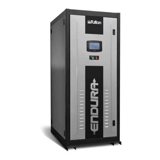
Endura (EDR)
Condensing Hydronic Boilers
750,000 - 2,000,000 BTU/HR
with SOLA Control
Serial/ National
Board Number
Model
Fulton Order
Owner
Site Name
Date
EDR-SOLA-IOM-2022-0216
Previous
Page
Next
Page
1
2
3
4
5
Advertisement
Need help?
Do you have a question about the Endura and is the answer not in the manual?
Ask a question
Questions and answers
Related Manuals for FULTON Endura
Boiler FULTON EDR-1000 Installation And Operation Manual
Endura series (edr) condensing hydronic boilers 1,000,000 - 2,000,000 btu/hr (68 pages)
Boiler FULTON Endura EDR-750 Installation And Operation Manual
Condensing hydronic boilers 750,000 - 2,000,000 btu/hr (92 pages)
Boiler FULTON Endura EDR 750 Nstallation, Operation And Maintenance Manual
Condensing hydronic boilers 750,000 - 2,000,000 btu/hr featuring pure control (196 pages)
Boiler FULTON Endura+ Series Installation And Operation Manual
Condensing hydronic boilers (82 pages)
Boiler FULTON Electropack Series Installation, Operation And Maintenance Manual
Electric steam boiler 18 kw-72 kw (56 pages)
Boiler FULTON EDR Installation, Operation And Maintenance Manual
Condensing hydronic boilers (118 pages)
Boiler FULTON EDR 750 Installation, Operation And Maintenance Manual
Condensing hydronic boilers (118 pages)
Boiler FULTON EDR 1000 Installation, Operation And Maintenance Manual
Condensing hydronic boilers (118 pages)
Boiler FULTON EDR 1500 Installation, Operation And Maintenance Manual
Condensing hydronic boilers (118 pages)
Boiler FULTON EDR 2000 Installation, Operation And Maintenance Manual
Condensing hydronic boilers (118 pages)
Boiler FULTON Endura XE Installation, Operation And Maintenance Manual
Condensing hydronic boilers (100 pages)
Boiler FULTON Endura EDR Installation, Operation And Maintenance Manual
Condensing hydronic boilers 750,000 - 2,000,000 btu/hr featuring pure control (112 pages)
Boiler FULTON ENDURA EXE-399 Quick Start Manual
Condensing hydronic boilers (2 pages)
Boiler FULTON PURE CONTROL User Manual
For endura xe condensing hydronic boilers (88 pages)
Boiler FULTON 60E Operator, Service & Parts Manual
E series gas fired steam boilers (44 pages)
Boiler FULTON VMP-W 40 -150 HP Installation And Operation Manual
Vertical multi-port hot water boilers (52 pages)
This manual is also suitable for:
Edr
Edr 750
Edr 1000
Edr 1500
Edr 2000
Print
Rename the bookmark
Delete bookmark?
Delete from my manuals?
Login
Sign In
OR
Sign in with Facebook
Sign in with Google
Upload manual
Upload from disk
Upload from URL


Need help?
Do you have a question about the Endura and is the answer not in the manual?
Questions and answers