
Related Manuals for FULTON VMP Series


Summary of Contents for FULTON VMP Series
- Page 1 INSTALLATION, OPERATION AND MAINTENANCE MANUAL VMP (vertical multi-port) Fuel Fired Steam Boiler This manual must be available to the boiler operator at all times. VMP-IOMM-2018-2...
-
Page 2: Table Of Contents
TABLE OF CONTENTS Fulton Ltd Warnings & Cautions Explained Gas Monoblocs-Non Modulating Burner Warnings & Cautions In Manual 3.3.1 Multi Bloc Gas Valves Regulations Cleaning Steam Lines and Pressure Vessels SECTION 1 - INTRODUCTION SECTION 4 - OPERATION General General... - Page 3 TABLE OF CONTENTS Fulton Ltd 5.8.6 After 5 Years 5.8.7 After All Repairs & Maintenance in addition Maintenance Record Keeping SECTION 6 - TROUBLESHOOTING Troubleshooting-Gas boiler Troubleshooting-Oil boiler Troubleshooting-feedwater pump Troubleshooting-Siemens LMV APPENDIX A - TI SHEETS VMP Dimensions & Specification Water Level Probes...
-
Page 4: Iwarnings & Cautions Explained
SAFETY PRECAUTIONS Fulton Ltd WARNINGS & CAUTIONS EXPLAINED For your safety! The following WARNINGS, CAUTIONS and NOTES appear in various sections of this manual. It is the responsibility and duty of all personnel involved • WARNINGS must be observed to prevent serious in the operation and maintenance of this equipment injury or death to personnel. - Page 5 The importance of correct burner adjustment to achieve you do not understand. Obtain a service manual from low emissions, safe, clean and efficient combustion Fulton Ltd or call a Fulton service engineer. is paramount. Poor combustion, where unburnt gas forms carbon monoxide is both a health hazard, and...
- Page 6 Low feedwater temperature can result in thermal shock to the boiler pressure vessel. Return the maximum amount of condensate and if necessary preheat the Should you suspect that the boilers flue passage ways feedwater. If in doubt consult Fulton Ltd. have become blocked, contact your authorized Fulton representative. Page VI...
-
Page 7: Regulations
The Pressure System Safety Regulations 2000 Fulton boilers fall within the scope of the Pressure Systems Examination Scheme. Regular inspections are therefore required by a competent person. The scope of the examination and the actual intervals between examinations is at the discretion of the competent person. - Page 8 Fulton Ltd Page VIII VMP-IOMM-2018-2...
-
Page 9: Section 1 - Introduction
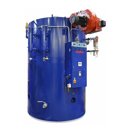
• Crating inspection This manual is provided as a guide to the correct operation and maintenance of your Fulton equipment, and should be read in its entirety and be made permanently available to the staff responsible for the operation of the boiler. It should not, however, be considered as a complete code of practice, nor should it replace existing codes or standards which may be applicable. - Page 10 INTRODUCTION - 1 Fulton Ltd Figure. 1 - General Arrangement Page 2 VMP-IOMM-2018-2...
- Page 11 INTRODUCTION - 1 Fulton Ltd Figure. 2 - General Arrangement Top 1. Boiler pressure gauge 16. Clean out handhole (water jacket) 2. Burner scroll (air intake) 17. Clean out door (furnace) 3. Water bottle containing water level probes 18. Feedwater inlet 4.
- Page 12 Fulton Ltd Figure. 3 - Boiler name plate Description Comments Unique number given to each Fulton boiler for identification Boiler serial number Name of product Product model Type of product Product group Year that the product was made (not year boiler was sold or commissioned) Year of manufacture...
-
Page 13: Section 2 - Installation
INSTALLATION - 2 Fulton Ltd SECTION 2 - INSTALLATION GENERAL The installation of a VMP fuel fired steam boiler should be carried out by competent personnel in accordance with all relevant safety regulations. It is the responsibility of the installer to ensure that these regulations are complied with. The requirements and instructions contained in this section generally relate to the boilers being installed to operate on natural/manufactured gas. -
Page 14: Siting
INSTALLATION - 2 Fulton Ltd 2.2.2 SITING WARNING Failure to provide required and safe access to the equipment could impede commissioning and maintenance. Service technicians are instructed not to commence commissioning if hazardous conditions exist. (Reference should be made to Utilisation Procedures as stated in IGE/UP/10 Part 1 Communication 1676, and in particular to Section 5, Location of Appliances). - Page 15 Fulton Ltd Safety Valves Safety Valves Water Column Return Water Column and Sight Glass Sight Glass Vent Gas Fired Gas Fired Vent Cold Water Supply Sight Glass Shut Off Shut Off Valve Check Valves Valve Check Valves Condensate Blowdown Discharge...
-
Page 16: Connections
Regulations exist covering such items and care must be taken to ensure compliance with these regulations. If in doubt regarding blowdown arrangements, consult Fulton Ltd or Health and Safety Executive Guidance Note PM60 which covers blowdown tanks and associated pipework installation. -
Page 17: Main Boiler Blowdown Valve
INSTALLATION - 2 Fulton Ltd 2.4.2.1 MAIN BOILER BLOWDOWN VALVE The main blowdown connection is via a branch pipe. Feedwater inlet Front Boiler blowdown Rear Boiler blowdown Figure. 5 - Boiler Blowdown 2.4.2.2 WATER BOTTLE Boilers are supplied with two water bottles containing the water level and pump on/off probes. -
Page 18: Water Level Gauge Set (Sight Glass)
INSTALLATION - 2 Fulton Ltd 2.4.2.3 WATER LEVEL GAUGE SET (SIGHT GLASS) Boilers are normally supplied with two complete water level gauge sets (sight glasses). The water level gauge blowdown cock should be connected to the auxiliary blowdown line from the water bottle blowdown valve by 3/8 in. -
Page 19: Main Steam Valve
INSTALLATION - 2 Fulton Ltd 2.4.4 MAIN STEAM VALVE Distribution pipework should be run from the main steam valve on the boiler to the steam delivery point(s). Care should be taken to ensure that adequate condensate drainage and expansion facilities are provided within the pipework run(s). -
Page 20: Fuel Supply
INSTALLATION - 2 Fulton Ltd FUEL SUPPLY WARNING Do not change the boiler fuel without consulting the boiler manufacturer. 2.5.1 GAS SUPPLY Verify that the burner is suitable for the type of gas being supplied. Ensure that the piping from the meter is the correct size, and that a gas cock is inserted in the line between the boiler and the meter. -
Page 21: L.p.gas Gas Supply - Propane / Butane
For L.P.G. applications the inlet pressure switch is used to protect the system from over pressure and should be set at 100 mbar. Further information Firing LPG fuels in a Fulton Vertical boiler is relatively straightforward, however the nature of the fuel makes it difficult to ensure that the correct gas flow rate is achieved when commissioning and servicing the burner. -
Page 22: Oil Supply
INSTALLATION - 2 Fulton Ltd The golden rule with LPG fuels is therefore when in doubt, under fire, ensuring that there is adequate adjustment remaining on the air inlet damper for additional air, and that the exhaust gas analysis readings are 0 - 10 ppm of CO maximum, with CO2 in the range 9.0 - 10.0 % maximum. -
Page 23: Electrical Requirements
Note: Single skid systems are generally shipped completely pre-wired. Note: The power ratings and requirements are given in Appendix A - TI-128-VMP Series Dimensions & Specification. Note: It is advisable for dual fuel burners, that the offline fuel is manually isolated with a proof of closure microswitch that is interlocked with the online control circuit. - Page 24 INSTALLATION - 2 Fulton Ltd Remote Stop. The Remote Stop option allows the customer to fit a remote stop pushbutton / contact. An open contact will stop the boiler. It should be wired between terminals 13 & 15 as shown. If a Remote Alarm panel is fitted, wire the remote stop between terminals 13 & 14. Note: A factory fitted link must be removed to use this option (Contact Rating 230V 4A Min.).
- Page 25 INSTALLATION - 2 Fulton Ltd Figure. 10 - Electrical Customer Terminal Connections Page 17 VMP-IOMM-2018-2...
-
Page 26: Water Supply
The chemicals required to operate the water softeners and chemical treatment plants CAN BE SUPPLIED by Fulton. It is the responsibility of the operator to ensure adequate supplies of chemical are available at all times (including commissioning). Costly repairs could be required should the plant operate without chemicals or the wrong dosage of chemicals. -
Page 27: Glossary Of Water Supply Terms
INSTALLATION - 2 Fulton Ltd 2.7.1 GLOSSARY OF WATER SUPPLY TERMS Dissolved Oxygen: Oxygen that is dissolved in Oil: Oil is not a natural constituent of boiler water; the feedwater will cause the steel in the boiler and still it can frequently enter a system through leaks in the feedwater system to be attacked by the water a condenser or other heat exchanger. -
Page 28: Piping Specifications
INSTALLATION - 2 Fulton Ltd Dissolved Solids: Dissolved solids are salts in the Chemical Dosing: In addition to softening the water that stay in solution. They are invisible to the feedwater, it is also important to consider other factors naked eye. As the boiler generates steam, dissolved such as dissolved oxygen and acidity. -
Page 29: Insulation
INSTALLATION - 2 Fulton Ltd INSULATION WARNING After the appropriate system tests have been satisfactorily completed, all hot pipework and vessels must be adequately insulated with material suited to the temperature and application to prevent both heat loss and personnel injury. Note: It is recommended that for inspection and maintenance, pumps, flanges, valves and fittings be left uninsulated but suitably shielded for safety. - Page 30 Fulton Ltd Page 22 VMP-IOMM-2018-2...
-
Page 31: Section 3 - Commissioning
Fulton Ltd SECTION 3 - COMMISSIONING COMMISSIONING THE BOILER It is essential that the commissioning procedures listed below are carried out by a Fulton service engineer who will have the necessary experience and testing equipment to ensure that the installation is not only correct, but is operating safely and at optimum efficiency. -
Page 32: Boiler Inspection And Initial Firing-Dual Fuel Burner
COMMISSIONING - 3 Fulton Ltd 3.1.1 BOILER INSPECTION AND INITIAL FIRING DUAL FUEL BURNER Dual fuel boilers that use a common burner assembly and have a switch change over from one fuel to another, have to be commissioned on the basis of a primary fuel (usually gas), with the secondary fuel as a back-up. - Page 33 COMMISSIONING - 3 Fulton Ltd 9. Open all the valves in the water feed line. Switch on the feedwater pump motor and fill the boiler (see Section 4.5 - Filling the boiler). The operation of the pump controls should be checked by using the boiler blowdown valve (located at the rear of the boiler). When the water level gauge (sight glass) is reading two thirds full, the pump will stop.
-
Page 34: Boiler Inspection And Initial Firing-Oil Burner
COMMISSIONING - 3 Fulton Ltd 3.1.4 BOILER INSPECTION AND INITIAL FIRING OIL BURNER Note: Always place the highest value nozzle (engraved on the side of the nozzle) into the low fire oil supply port in the manifold. 1. Ensure that the boiler has been washed out after installation. It is advisable to conduct a water analysis before operating the boiler. -
Page 35: Low/High Fire
COMMISSIONING - 3 Fulton Ltd 15. After the burner has been firing for approximately five minutes, adjust the main air control gate located on the burner scroll, to obtain a clean combustion. See typical combustion values given in Appendix A - TI 128. 16. Observe the flame through the observation glass and adjust the primary/secondary air control located on the burner, so that the flame can be seen passing down the blast tube. 17. Check the operation of the low water safety controls (see Section 5.4.2 - Low Water Level Check). -
Page 36: Fully Modulating
COMMISSIONING - 3 Fulton Ltd 3.2.2 FULLY MODULATING The correct setting for fully modulating operation is made by adjusting the parameters via the Siemens LMV burner controller. All adjustments need to be carried out by a suitably trained service engineer. -
Page 37: Multi Bloc Gas Valves
COMMISSIONING - 3 Fulton Ltd 3.3.1 MULTI BLOC GAS VALVES Main gas line isolating valve Pilot line Pilot line Pilot line Main gas valve isolation governor gas valves assembly ball valve Figure. 12 - Gas Valve (non modulating burner) actuator... - Page 38 COMMISSIONING - 3 Fulton Ltd Note: See attached manufacturers leaflets. Output pressure controller adjusting screw Operating indicator Hydraulic Brake Adjustable pressure Main gas flow adjustment switch Test point connection Test point connection downstream of Valve 1 Gas output flange Gas input filter cover Test point connection Test point connection...
- Page 39 COMMISSIONING - 3 Fulton Ltd Hydraulic brake Main gas flow adjustment Output pressure controller adjusting High fire solenoid screw Operating pressure indicators Low fire flow adjustment Input gas test point Adjustable pressure switch Test point 1 downstream (internal leak test) Gas input mounting flange location Test point 2 downstream Test point 1upstream Figure.
-
Page 40: Cleaning Steam Lines And Pressure Vessels
COMMISSIONING - 3 Fulton Ltd CLEANING STEAM LINES AND PRESSURE VESSELS During the first week of boiler operation, clean all oil and dirt from the boiler, the steam line and condensate return line. 1. Disconnect the condensate return pipe adjacent to the condensate return tank. 2. Direct the returns to a floor drain or other safe discharge point and make safe. 3. Leave in this position for one week to allow all impurities to flush through. 4. Drain the boiler completely each day. 5. After the week is completed, drain and flush the condensate return tank, removing all installation sediment. -
Page 41: Section 4 - Operation
Fulton Ltd SECTION 4 - OPERATION CAUTION The following instructions are given for the guidance of the operator in the use of the Fulton steam boiler. No responsibility can be accepted by Fulton Ltd if these instructions are ignored. GENERAL... -
Page 42: Boiler Controls
OPERATION - 4 Fulton Ltd 4.2.1 BOILER CONTROLS Note: All the limiters are of the ‘fail-safe’ type and are wired in series; failure of any one will automatically shut down the boiler. Low Water Limiters, Feedwater Pump Relay and High Water Level Relay... -
Page 43: Boiler Control Panel
OPERATION - 4 Fulton Ltd 4.2.2 BOILER CONTROL PANEL Indicator lights are fitted to the control panel as an additional aid to the operator. The meaning and operating sequence of these lights is as follows: CAUTION The power on light is derived from a single phase. It is possible that with the control phase down or a defective bulb the other phases could be live. - Page 44 OPERATION - 4 Fulton Ltd Gas Valve CPI (closed position indicator) The valve switch is located on the main gas valve. This is monitored by the burner controller and shows a green indicator when the valve is closed. Burner Fan This light indicates that the burner motor contactor is energised.
- Page 45 OPERATION - 4 Fulton Ltd Remote Panel Disable (inside boiler panel) Pressing this button will disarm the remote alarm panel to avoid nuisance remote alarms whilst maintenance is undertaken. Figure. 17 - Control Panel (Dual Fuel) Page 37 VMP-IOMM-2018-2...
-
Page 46: Steam Pressure Controls
OPERATION - 4 Fulton Ltd 4.2.3 STEAM PRESSURE CONTROLS Pressure controls are mounted on the side of the control box. Pressure controls are as follows: Operating Pressure Switch (On/Off) Controls the ON/OFF cycle of the burner, switching the burner off when the desired steam pressure is reached and switching it on when steam pressure falls. -
Page 47: Setting Pressure Controls
OPERATION - 4 Fulton Ltd 4.2.3.1 SETTING PRESSURE CONTROLS If the pressure control is fitted with a differential scale: 1. Set the main scale pressure to the maximum pressure required (system pressure). Do not exceed the boiler operating pressure. 2. Set the differential scale to it’s minimum pressure. If the pressure control has a fixed differential, i.e. no adjustable differential scale, set the main scale to the maximum pressure required. -
Page 48: Primary Air Adjustment (Auto)
OPERATION - 4 Fulton Ltd PRIMARY AIR ADjUSTMENT (AUTO) The primary air adjustment or main air control is located at the fan housing face. This control is used to supply the burner with excess air needed to facilitate good combustion. Too much or too little air will result in poor combustion. -
Page 49: Filling The Boiler-All Models
OPERATION - 4 Fulton Ltd FILLING THE BOILER ALL MODELS 1. The door isolator should be in the OFF position. 2. Ensure the Boiler and Pump Switches are in the OFF position. 3. Ensure the following valves are OPEN: a) Main steam stop valve. -
Page 50: Draining The Boiler
OPERATION - 4 Fulton Ltd DRAINING THE BOILER CAUTION Your local regulations could state boiler water above 43 °C must not be discharged into the drain. ALWAYS check your local regulations. Boilers with manual blowdown valves 1. Ensure the boiler is cold. -
Page 51: Boiler Start-Up (From Cold)-All Models
OPERATION - 4 Fulton Ltd BOILER START-UP (FROM COLD) ALL MODELS 1. Fill the boiler (see Section 4.5 - Filling The Boiler). 2. Ensure the main steam isolating valve is SHUT. 3. Open all the valves in the gas train/oil supply. It is assumed that the fuel supply lines have been purged prior to attempting to start the boiler/burner. -
Page 52: Boiler Start-Up Following Short Term Shut-Down
OPERATION - 4 Fulton Ltd 4.7.1 BOILER START-UP FOLLOWING SHORT TERM SHUT-DOWN If the boiler has been shut-down short term (see Section 4.8.1 - Short Term Shut-Down), the large thermal mass in the boiler will maintain the internal temperature to a point that the boiler can be simply switched on (preferably on low fire) and then left to reach working temperature/ pressure. -
Page 53: Section 5 - Maintenance
MAINTENANCE - 5 Fulton Ltd SECTION 5 - MAINTENANCE CAUTION It is vitally important that the instructions given in this manual are strictly adhered to. Failure to carry out the daily, weekly, monthly and six monthly checks could result in a drastic reduction in the life expectancy of the boiler. -
Page 54: Burner Flame Sensor Test
MAINTENANCE - 5 Fulton Ltd BURNER FLAME SENSOR TEST This test checks the operation of the flame safeguard sensor. 1. Ensure that the burner is firing. 2. Remove the flame sensor from its plug-in connection on the top of the burner. 3. Cover the sensor glass to exclude all light. 4. The burner control should go to a lockout/flame failure condition (2 - 3 sec gas, 34 sec oil) and will require manual resetting. Note: The fan will run on for a short time but the flame should go out. -
Page 55: Water Level And Low Water Safety Control Procedures
MAINTENANCE - 5 Fulton Ltd WATER LEVEL AND LOW WATER SAFETY CONTROL PROCEDURES The following procedures ensure the correct functioning of the water level controls and the low water safety controls. 5.4.1 FEEDWATER PUMP TEST a) If the boiler is not firing and not under steam pressure, lower the water level using the main blowdown valve: If the pump is running: 1. -
Page 56: Low Water Level Check
MAINTENANCE - 5 Fulton Ltd 5.4.2 LOW WATER LEVEL CHECK 1. Ensure that the boiler is firing, the feedwater pump is not running and that the water level is between Pump On and Pump Off. 2. Switch the Pump switch to the OFF position. 3. Allow the water level to lower by natural evaporation below the Low Water level. -
Page 57: Blowdown Procedures
Keep the boiler, water level gauge (sight glass), water bottle and interconnecting pipework free from sludge and scale build-up by blowing down in the following manner: Note: Where a boiler is operating continuously at steam pressure, advice should be sought from Fulton Service Department regarding the appropriate blowdown procedure. -
Page 58: Water Level Gauge (Sight Glass) Blowdown
OPEN and all blowdown valves are CLOSED. Note: Where a boiler is operating continuously at steam pressure, advice should be taken from Fulton Ltd as to the appropriate blowdown procedure. BOILER INTERNAL INSPECTION The lower hand hole doors should be... -
Page 59: Fitting New Gaskets To Boiler Inspection Holes
MAINTENANCE - 5 Fulton Ltd FITTING NEW GASKETS TO BOILER INSPECTION HOLES 5.7.1 IMPORTANT INFORMATION CAUTION TOPOG-E gasket have a finite life after installation and must be renewed annually. It is important that the instructions given in this section are adhered to. The VMP boilers are fitted with TOPOG-E gaskets in all the inspection holes of the boiler. These gaskets work very well and millions have been safely used over the last 30 years, however, it is absolutely essential to observe a few simple rules in order to get the best performance from your installation. -
Page 60: Fitting Procedure
MAINTENANCE - 5 Fulton Ltd 5.7.2 FITTING PROCEDURE Blowdown the boiler completely (see Section 5.5.1 - Main Boiler Blowdown) and examine all inspection holes in the boiler. If any leakage is evident, proceed as follows: 1. Disassemble the crab and cover plate and remove the inspection hole assembly. -
Page 61: Schedule Of Operator Tests And Checks
Fulton Ltd SCHEDULE OF OPERATOR TESTS AND CHECKS The following schedule is the advice of Fulton Ltd. The frequency of tests and checks may vary according to site risk assessment and/or specific requirements of the country/territory that the boiler is installed in. Failure to maintain the boiler adequately may void the Fulton guarantee. -
Page 62: Daily
MAINTENANCE - 5 Fulton Ltd 5.8.1 DAILY WARNING All steam pipework, valves and fittings will be very hot. 1. Visually inspect for signs of leakage: a) Steam and feedwater pipework. b) Valves and fittings. c) Hand holes If leakage is evident, the gasket needs replacing. If leaks are suspected, shut down and evacuate the system to atmospheric pressure before attempting to repair the leaks. -
Page 63: Monthly-In Addition
If any leakage is evident, the gasket needs replacing (see Section 5.7). 12. Clean any water traps and strainers fitted in the feedwater line. Check feedwater and boiler water quality against the values given in Appendix A - TI-139- Recommended Water Conditions. Note: Use only genuine Fulton replacement parts. 5.8.4 SIX MONTHLY SERVICE WARNING Maintenance on gas related parts of a boiler must be carried out by competent, trained personnel who are GAS SAFE/ACS registered, and who have the necessary equipment to check combustion. -
Page 64: Annual Service
9. Inspect and clean blowdown separator if part of installation. 5.8.6 AFTER 5 YEARS 10. Fulton Ltd recommend replacement of all threaded stub pipes on the boiler OR to your inspectors satisfaction. 5.8.7 AFTER ALL REPAIRS & MAINTENANCE IN ADDITION 1. -
Page 65: Maintenance Record Keeping
Boiler log sheets should be completed on a regular basis, this provides invaluable information in the subsequent investigation of the boiler history. Maintenance log sheets can be found in the Fulton boiler Log Books provided by Fulton. To Purchase a Fulton Boiler Log Book, please contact training@fulton.co.uk. Model: Fuel:... - Page 66 Fulton Ltd Page 58 VMP-IOMM-2018-2...
-
Page 67: Section 6 - Troubleshooting
TROUBLESHOOTING - 6 Fulton Ltd SECTION 6 - TROUBLESHOOTING TROUBLESHOOTING GAS BOILER Problem Cause Remedy 1. Gas supply Check for gas pressure and intermittent supply problems. 1. Ignition Failure 2. Power Supply Check fuse or circuit breaker. Reset or Replace as required. - Page 68 TROUBLESHOOTING - 6 Fulton Ltd TROUBLESHOOTING GAS BOILER Problem Cause Remedy 1. Power Supply Check fuse or circuit, reset or replace as necessary. 3. Flame Failure During Normal Run 2. Gas Supply Check gas pressure coming into the gas train, if low contact the gas supplier.
- Page 69 TROUBLESHOOTING - 6 Fulton Ltd TROUBLESHOOTING GAS BOILER Problem Cause Remedy 1. Refractory bricks Check the bricks are not plugged with soot or broken into 6. Poor Combustion pieces. Clean and replace as required. 2. Stainless Steel Ring Check the ring is present (40J - 60J models) and fits tightly against the furnace wall.
- Page 70 Flush out and refill, if system operates but progressively glass) deteriorates, there is probably a leak somewhere in the system. 3. Scale buildup or lime deposits. Consult Fulton or call a water treatment specialist. 4. Too much compound (water Dump contents of the return tank and flush the system. treatment over dose). Test the water. 5. High Alkalinity (high pH).
-
Page 71: Troubleshooting-Oil Boiler
TROUBLESHOOTING - 6 Fulton Ltd TROUBLESHOOTING OIL BOILER Problem Cause Remedy 1. Oil Tank Empty Refill the oil tank. A slight delay in the re-priming of the 1. Ignition Failure fuel pump may cause the burner programmer to require resetting before the boiler operates satisfactorily. 2. Power Supply Check fuse or Circuit breaker. Reset or replace as required. - Page 72 TROUBLESHOOTING - 6 Fulton Ltd TROUBLESHOOTING OIL BOILER Problem Cause Remedy 1. No Power Check fuse or circuit breaker. Reset or replace as 3. Boiler fails to start necessary. 2. Pressure Control Disconnect all power to the controller. Disconnect the wires from the controller.
- Page 73 TROUBLESHOOTING - 6 Fulton Ltd TROUBLESHOOTING OIL BOILER Problem Cause Remedy 1. Refractory bricks Check the bricks are not plugged with soot or broken into 5. Poor combustion pieces. Clean and replace as required. 2. Stainless steel ring Check to ensure the ring is present and fits securely against the furnace wall.
- Page 74 TROUBLESHOOTING - 6 Fulton Ltd TROUBLESHOOTING OIL BOILER Problem Cause Remedy 1. Oil tank empty Refill the oil tank. A slight delay in the re-priming of the 7. Boiler will not fuel pump may cause the burner programmer to require maintain pressure resetting before the boiler operates satisfactorily. 2. Oil nozzle Check for blocked nozzle.
- Page 75 TROUBLESHOOTING - 6 Fulton Ltd TROUBLESHOOTING OIL BOILER Problem Cause Remedy 1. Scale on probes. Check probes, clean as required. 13. Water pump runs intermittently 2. Bad pump contactor. Check to ensure the contactor is live. Check to ensure the contactor coil is being pulled in.
-
Page 76: Troubleshooting-Feedwater Pump
TROUBLESHOOTING - 6 Fulton Ltd TROUBLESHOOTING FEEDWATER PUMP Problem Cause Remedy 1. Supply failure. Connect the electricity supply. 1. FEEDWATER PUMP Pump will not run 2. Fuses/Circuit Breakers are Replace fuses/Circuit Breakers. blown. 3. Motor contactor overload has Reactivate the motor protection. - Page 77 TROUBLESHOOTING - 6 Fulton Ltd TROUBLESHOOTING FEEDWATER PUMP Problem Cause Remedy 1. Cavitation occurs in the pump. Check the suction conditions. 8. Noise. 2. Pump does not rotate freely Adjust the pump shaft. (frictional resistance because of incorrect pump shaft position.
-
Page 78: Troubleshooting-Siemens Lmv
TROUBLESHOOTING - 6 Fulton Ltd TROUBLESHOOTING SIEMENS LMV Page 70 VMP-IOMM-2018-2... - Page 79 TROUBLESHOOTING - 6 Fulton Ltd Page 71 VMP-IOMM-2018-2...
- Page 80 TROUBLESHOOTING - 6 Fulton Ltd Page 72 VMP-IOMM-2018-2...
- Page 81 TROUBLESHOOTING - 6 Fulton Ltd Page 73 VMP-IOMM-2018-2...
- Page 82 TROUBLESHOOTING - 6 Fulton Ltd Page 74 VMP-IOMM-2018-2...
- Page 83 TROUBLESHOOTING - 6 Fulton Ltd Page 75 VMP-IOMM-2018-2...
- Page 84 TROUBLESHOOTING - 6 Fulton Ltd Page 76 VMP-IOMM-2018-2...
- Page 85 TROUBLESHOOTING - 6 Fulton Ltd Page 77 VMP-IOMM-2018-2...
- Page 86 TROUBLESHOOTING - 6 Fulton Ltd Page 78 VMP-IOMM-2018-2...
- Page 87 TROUBLESHOOTING - 6 Fulton Ltd Page 79 VMP-IOMM-2018-2...
- Page 88 TROUBLESHOOTING - 6 Fulton Ltd Page 80 VMP-IOMM-2018-2...
- Page 89 TROUBLESHOOTING - 6 Fulton Ltd Page 81 VMP-IOMM-2018-2...
- Page 90 TROUBLESHOOTING - 6 Fulton Ltd Page 82 VMP-IOMM-2018-2...
-
Page 91: Appendix A - Ti Sheets
Fulton Ltd APPENDIX A - TI SHEETS The Fulton boiler manual refers to a number of Fulton TI sheets. These TI sheets can be found in this Appendix. Note: The TI sheets in this appendix can be updated/replaced without revising the manuals issue number. To check you have the most up to date TI sheet, please check the downloads section on the Fulton website (www.fulton.co.uk/support/downloads) or consult Fulton Ltd. -
Page 92: Vmp Dimensions & Specification
APPENDIX - A Fulton Ltd Technical Information Sheet No. 128 Issue 3 VMP Series Dimensions & Specification Dimensions MODEL: VMP Minimum Clearance* 3175 3302 3353 Overall Width 1575 1727 1880 Overall Depth 2540 2896 3022 Overall Height 2984 3150 3200... - Page 93 APPENDIX - A Fulton Ltd Specification TI-128-VMP-DS-2017-3 MODEL: VMP UNIT CE marked to PED, EMC, LVD & Machinery Directive, constructed to BS2790 as standard (other code specifications available). General Steam Output F & A 100°C * kg/h 1252 1565 kW Rating...
-
Page 94: Water Level Probes
APPENDIX - A Fulton Ltd Technical Information Sheet No. 103 Issue 4 Water Level Probes Replacement Standard Probes (brass) Probes are supplied in a standard length and should be cut to the length required, (the length of the probe being replaced) ensuring measurements are taken from the underside of the probe hexagonal nut, remove any burrs caused by cutting. - Page 95 APPENDIX - A Fulton Ltd High Integrity Probes (stainless steel) TI-103-Water Level Probes-2017-4 The probe is supplied in two parts, the head and the tip. The tip should be screwed onto the head aligning the slot in the top of the tip with the hole in the screwed shaft of the head.
-
Page 96: Auto Tds Blowdown Systems
APPENDIX - A Fulton Ltd Technical Information Sheet No. 30 Issue 4 Automatic TDS Blowdown Systems The purpose of an Automatic, Total Dissolved Solids (TDS) Control Blowdown System, is to control the TDS level within the boiler around a set point. It is not a substitute for the main boiler blowdown, which must be used to control suspended solids, and prevent the build-up of sludge in the bottom of the boiler. - Page 97 The equipment and staff training required to carry out TDS sampling and calibration can be provided by Fulton. In order to achieve the maximum benefit from the installation of an Automatic TDS Blowdown System, it is strongly recommended that site personnel be provided with the necessary equipment, and training in order for them to fully understand the function of the system, and the possible consequences of their actions.
-
Page 98: Recommended Water Conditions
Fulton Ltd Technical Information Sheet No. 139 Issue 4 J Series & Electric Steam Boilers Recommended Water Conditions IMPORTANT It is very important that a strict water management program is followed to ensure trouble free boiler operation. The following are recommended for feedwater and for boiler water... -
Page 99: Appendix B - Wiring Diagrams
APPENDIX - B Fulton Ltd APPENDIX B - WIRING DIAGRAMS GENERAL Wiring diagrams are available from Fulton Ltd on request. Boiler Fuel Controls Arrangement 1 Arrangement 2 Arrangement 3 80-150 Modulating Modulating Dual Fuel Modulating 150VD324M3 Page 91 VMP-IOMM-2018-2... - Page 100 Fulton Ltd Page 92 VMP-IOMM-2018-2...
-
Page 101: Appendix C - Spare Parts
Installing non-authorised components and non-approved modifications/conversion can compromise safety and may invalidate your warranty. For replacements, use only original spare parts from Fulton or those which are approved by Fulton. To order spare parts please contact Fulton spares department at spares@fulton.co.uk or call the Fulton Ltd main number (+44 (0) 117 972 3322). - Page 102 APPENDIX - C Fulton Ltd Page 94 VMP-IOMM-2018-2...
-
Page 103: Appendix D - Spirax High Integrity Level Controls
APPENDIX - D Fulton Ltd APPENDIX D - SPIRAX HIGH INTEGRITY LEVEL CONTROLS DAILY TESTS The daily testing of boiler water level controls is a mandatory requirement as defined in the Health & Safety Executive Guidance Note BG01, Arrangements 2 and 3. The level of supervision is dependent upon the type of level controls (limiters) fitted. Boilers fitted with self monitoring high integrity controls (limiters) should be tested daily by a qualified boiler attendant, but may be supervised during the silent hours and weekends by a competent person trained to respond to an alarm. Daily testing of the controls is required which can be by simulation, with a weekly test by interrupting the feedwater pump and lowering the water by evaporation. -
Page 104: Weekly Test In Addition
APPENDIX - D Fulton Ltd WEEKLY TEST IN ADDITION 1.2.1 LOW WATER WEEKLY IN ADDITION with the burner firing: 1. Switch the Pump switch to the Pump OFF position. 2. By evaporation, lower the water level in the boiler until the Low Water alarm sounds, the Low Water Reset buttons illuminate, and the burner shuts down. - Page 105 G U A R A N T E E On the Fulton Boiler Pressure Vessel Fulton Ltd will repair or replace EXW factory any Fulton pressure vessel which within five (5) years of the date of delivery is found to be defective in workmanship, or material, provided this equipment is operated and maintained by the buyer for the purpose for which it was designed and in accordance with the manufacturer’s handbook.
- Page 106 VMP-IOMM-2018-2 Fulton Ltd 5 Fernhurst Road Fishponds Bristol BS5 7FG England Telephone: +44 (0) 117 972 3322 Fax: +44 (0) 117 972 3358 Email: sales@fulton.co.uk BS EN ISO 9001:2015 Company Registration 855790 England...
Need help?
Do you have a question about the VMP Series and is the answer not in the manual?
Questions and answers