Table of Contents
Advertisement
Quick Links
Download this manual
See also:
Operating Manual
Advertisement
Table of Contents

Related Manuals for VIA Technologies EPIA-M840


Summary of Contents for VIA Technologies EPIA-M840
- Page 1 EPIA-M840 Mini-ITX Embedded Board Revision 1.06 106-08262010-1438...
-
Page 2: Regulatory Compliance
PS/2 is a registered trademark of IBM Corporation. Disclaimer No license is granted, implied or otherwise, under any patent or patent rights of VIA Technologies. VIA Technologies makes no warranties, implied or otherwise, in regard to this document and to the products described in this document. The information provided in this document is believed to be accurate and reliable as of the publication date of this document. -
Page 3: Safety Precautions
Safety Precautions Do’s Always read the safety instructions carefully. Keep this User's Manual for future reference. All cautions and warnings on the equipment should be noted. Keep this equipment away from humidity. Lay this equipment on a reliable flat surface before setting it up. - Page 4 Box Contents and Ordering Information Model Number Description EPIA-M840-16 Standard kit 1 x SATA cable 1 x I/O bracket 1 x Driver CD EPIA-M840-12 Standard kit 1 x SATA cable 1 x I/O bracket 1 x Driver CD...
-
Page 5: Table Of Contents
ABLE OF ONTENTS 1 Overview ......................... 1 Key Components ....................2 VIA Nano™ NanoBGA2 CPU ..............2 VIA VX800 System Processor ..............2 Layout (top view) ....................3 Layout (I/O panel)....................5 Specifications ......................6 2 Hardware Installation..................8 External I/O ......................9 PS/2 ports...................... - Page 6 Memory module slots ................26 CPU fan and system fan connectors ..........28 Thermal sensor pin header ..............28 ATX power connector................29 DC-in power connector................30 CMOS battery....................30 Onboard Jumpers ....................31 LVDS jumper settings.................31 LVDS2 jumper settings ................31 SATA DOM power select .................32 CF power select ....................32 IDE DOM power select ................33 COM power select..................33 Clear CMOS jumper..................34...
- Page 7 CPU & PCI Bus Control ...................52 PCI Master 0 WS Write ................52 PCI Delay Transaction ................52 Integrated Peripherals..................53 Onboard LAN Boot ROM ................53 VIA OnChip IDE Device .................54 CF Card UDMA66 ..................54 SATA Controller.....................54 IDE DMA Transfer Access ................54 OnChip IDE Channel 1 ................54 IDE Prefetch Mode ..................54...
- Page 8 Serial ports......................57 Onboard Parallel Port.................57 Parallel Port Mode..................58 ECP Mode Use DMA ..................58 Internal IrDA Controller................58 IR IRQ ........................58 IR DMA ......................58 USB Device Setting ...................59 USB 1.0 Controller ..................59 USB 2.0 Controller ..................59 USB Operation Mode ................59 USB Keyboard Function................59 USB Mouse Function .................59 USB Storage Function................60 Power Management Setup................61...
- Page 9 Maximum Payload Size................67 IRQ Resources .....................68 PC Health Status....................69 Frequency/Voltage Control.................70 DRAM Frequency ..................70 DDR CAS Latency Control ...............70 DDR Burst Length..................70 DDR 1T Command Rate ................70 DRDY Table .....................70 ODT........................70 Spread Spectrum ..................71 Load Optimized Defaults................72 Set Supervisor/User Password ..............73 Save &...
-
Page 10: Overview
Overview... -
Page 11: Key Components
SATA 3Gb/s storage devices as well as IDE. The EPIA-M840 is based on the VIA VX800 Unified Digital Media IGP chipset featuring the VIA Chrome9™ HC3 with 2D/3D graphics and video accelerators for rich digital media performance. -
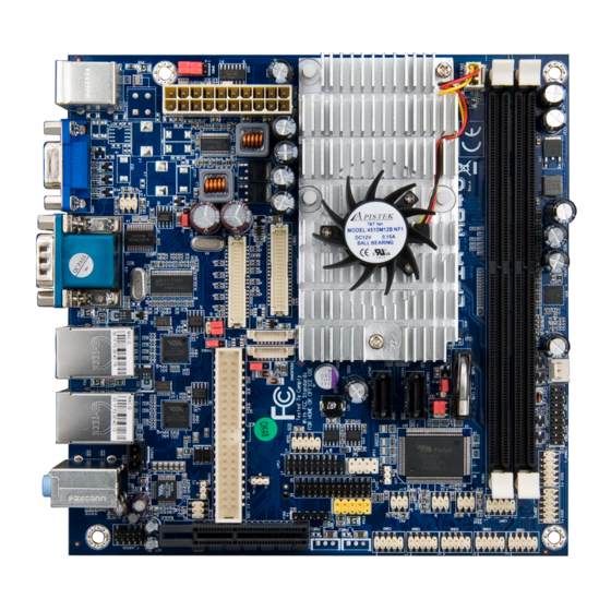
Page 12: Layout (Top View)
AYOUT TOP VIEW... - Page 13 Description Page DC-in power connector (DC12V1) PS/2 keyboard and mouse pin header (KBMS) ATX power supply connector (ATX_POWER1) VIA Nano CPU (U16) VIA VX800 chipset (U15) CPU fan connector (CPUFAN1) Memory slots (DIMM1, DIMM2) LVDS connectors (LVDS1, LVDS2) CMOS battery socket (BAT1)
-
Page 14: Layout (I/O Panel)
(I/O AYOUT PANEL Item Description Page PS/2 keyboard port COM ports Gigabit Ethernet ports Line-in 3.5 mm TRS jack Line-out 3.5 mm TRS jack PS/2 mouse port VGA port USB 2.0 ports Microphone 3.5 mm TRS jack... -
Page 15: Specifications
2 x SATA 3.5” HDD auxiliary power (for DC-in SKU only) 1 x CF type 1 2 x VIA VT6130 PCIe Gigabit Ethernet controller VIA VT1708S High Definition audio codec Audio 1 x USB pin header (supports two USB ports) - Page 16 System Monitoring - Wake-on-LAN, keyboard power-on, RTC timer, Watch Dog timer - System power management - AC power failure recover Operating environment 0°C ~ 60°C 0% ~ 95% (relative humidity; non-condensing) Form Factor Mini-ITX (17 cm x 17 cm) Certifications CE/FCC Compliance RoHS...
-
Page 17: Hardware Installation
Hardware Installation... -
Page 18: External I/O
There are two 9-pin COM port is for pointing devices or other serial devices. Gigabit LAN ports The mainboard provides two Gigabit Ethernet port controlled through the VIA VT6130 PCIe Gigabit Ethernet controller. USB ports Four standard USB 2.0 ports are provided. Audio ports Three 3.5 mm TRS jacks enable connections to Line-out, Line-in,... -
Page 19: Onboard Connectors
NBOARD CONNECTORS LVDS panel connectors The mainboard has two LVDS panel connectors: LVDS1 and LVDS2. - Page 20 LVDS1 Signal Signal -LD2C0 PVDD1 +LD2C0 PVDD1 -LD2C1 +LD2C1 -LD1C0 +LD1C0 -LD2C2 +LD2C2 -LD1C1 +LD1C1 -LCLK2 +LCLK2 -LD1C2 +LD1C2 -LD2C3 +LD2C3 -LCLK1 +LCLK1 -LD1C3 +LD1C3 DVP1_SPCLK DVP1_SPD LVDS2 Signal Signal -A4_L PVDD2 A4_L PVDD2 -A5_L A5_L -A0_L A0_L -A6_L A6_L -A1_L A1_L -CLK2_L...
-
Page 21: Inverter Connectors
Inverter connectors The mainboard has two inverters for controlling the LVDS panel backlight and brightness. INVERTER1 corresponds to the LVDS1 panel connector. INVERTER2 corresponds to the LVDS2 panel connector. INVERTER1 INVERTER2 Signal Signal IVDD1_CEN IVDD2 IVDD1_CEN IVDD2 BLON1 BAKLITE VX800PWM_CTL VX800PWM_CTL BLON1 BAKLITE... -
Page 22: Sata Connectors
SATA connectors There are two onboard SATA connectors that support data transfers speeds up to 3 Gbps. Both 2.5-inch and 3.5-inch SATA drives can be supported. The standard mainboard version can only support 2.5-inch SATA hard drives. The DC-in mainboard version can only support 3.5-inch SATA hard drives. -
Page 23: Sata Power Connectors
SATA power connectors The DC-in SKU version of the mainboard provides two 3-pin SATA power connectors. Each SATA power connector provides an auxiliary 12V power supply to attached 3.5-inch SATA hard drives. When connecting SATA power cables to the SATA power connectors, make sure that the power plugs are inserted in the proper orientation and the pins are properly aligned. -
Page 24: Ide Connector
IDE connector The mainboard has one IDE connector that provides support for up to two IDE devices. Signal Signal -IDE_RST PD_7 PD_8 PD_6 PD_9 PD_5 PD_10 PD_4 PD_11 PD_3 PD_12 PD_2 PD_13 PD_1 PD_14 PD_0 PD_15 IDEV_SEL PD_REQ -PD_IOW -PD_IOR PD_RDY -PD_ACK PD_IRQ15... -
Page 25: Compact Flash Slot
Compact Flash slot The onboard CompactFlash socket is located on the bottom side of the mainboard. It is compatible with Type 1 and Type 2 CompactFlash cards. -
Page 26: Pcie Slot
PCIe slot The onboard PCI Express slot supports one PCIe x4 expansion card. USB pin header The onboard USB pin header enables the addition of two more USB 2.0 ports. Signal Signal VUSB4 VUSB4 USBD_T2- USBD_T3- USBD_T2+ USBD_T3+ —... -
Page 27: Rs232 Com Pin Headers
RS232 COM pin headers The mainboard includes six COM pin headers onboard. Signal Signal COM_DCDX COM_RXDX COM_TXDX COM_DTRX COM_DSRX COM_RTSX COM_CTSX COM_RIX —... -
Page 28: Digital I/O Pin Headers
Digital I/O pin headers The mainboard includes two Digital I/O pin headers that support eight GPO and eight GPI pins. DIO1 DIO2 Signal Signal Signal Signal 5V_DIO 12V_DIO 5V_DIO 12V_DIO GPO_23 GPI_03 GPO_27 GPI_15 GPO_22 GPI_02 GPO_26 GPI_11 GPO_21 GPI_01 GPO_25 GPI_10 GPO_20... -
Page 29: Lpt Pin Header
LPT pin header The mainboard includes one onboard LPT pin header. Signal Signal -LP_STB -LP_AFD LP_D0 -LP_ERR LP_D1 -LP_INIT LP_D2 -LP_SLIN LP_D3 LP_D4 LP_D5 LP_D6 LP_D7 -LP_ACK LP_BUSY LP_PE LP_SLCT... -
Page 30: Lpc Pin Header
LPC pin header The mainboard includes one LPC pin header. Signal Signal LPC_AD1 LPC_33_CLK -PCI_RST-1 LPC_AD0 LPC_48_CLK LPC_AD2 -LPC_FRAME SERIRQ LPC_AD3 -LPC_DRQ1 -EXTSMI +3.3V +3.3V —... -
Page 31: Fir Pin Header
FIR pin header The onboard FIR pin header enables connections to IR optics. Signal IRRX2 IRRX IRTX SMBus pin header The mainboard includes an SMBus pin header. Signal SMB_CLK SMB_DAT... -
Page 32: Mfx Pin Header
MFX pin header The mainboard includes an MFX pin header. Signal Signal +5VSUS PW_BN SMB_CLK SMB_DAT — SPI pin header The onboard SPI pin header provides support for one full-duplex serial slave device. Signal Signal SPI_VCC SPI_SS0 SPI_CLK SPI_DI SPI_DO —... -
Page 33: Spdif Connector
SPDIF connector The mainboard includes one SPDIF connector. Signal SPDIF_O PS/2 keyboard and mouse pin header The mainboard includes one pin header for adding support for PS/2 keyboard and mouse. Signal Signal +5VDUAL KB_CLK KB_DAT EKBCLK EKBDATA MS_CLK MS_DAT EMSCLK EMSDATA... -
Page 34: Front Audio Pin Header
Front audio pin header The mainboard has one pin header for connecting to front panel switches and status LEDs. Signal Signal HPOUTR HPOUTL MIC2IN_R MIC2IN_L — AGND AGND Front panel pin header The mainboard has one pin header for connecting to front panel switches and status LEDs. -
Page 35: Memory Module Slots
Memory module slots The mainboard includes two DIMM memory module slots. - Page 36 To install the memory modules: Disengage the locking mechanism at both ends of the DIMM slot. Align the notch at the bottom of the DIMM with the counterpart on the DIMM slot. Then insert the DIMM into the slot and push down at both ends until the locking clips snap into position.
-
Page 37: Cpu Fan And System Fan Connectors
CPU fan and system fan connectors CPUFAN1 and SYSFAN1 run on +5V and maintains system cooling. When connecting the cable to the connector, always be aware that the red wire (positive wire) should be connected to the +5V pin. The black wire is the ground wire and should always be connected to GND. -
Page 38: Atx Power Connector
ATX power connector The mainboard supports a conventional ATX power supply for the power system. Before inserting the power supply connector, always make sure that all components are installed correctly to ensure that no damage will be caused. To connect the power supply, make sure the power plug is inserted in the proper orientation and the pins are aligned. -
Page 39: Dc-In Power Connector
DC-in power connector The mainboard has a 12V DC connector onboard. The 12V DC is needed if 3.5-inch SATA drives will be used with the mainboard. Signal Signal +12VDC +12VDC CMOS battery The onboard battery provides power to the CMOS RAM. If disconnected all configurations in the CMOS RAM will be reset to factory defaults. -
Page 40: Onboard Jumpers
NBOARD UMPERS LVDS jumper settings The LVDS connectors and LVDS inverters can operate on different input voltages. Pins 1, 3, and 5 correspond to INVERTER1. Pins 2, 4, and 6 correspond to LVDS1. INVERTER1 power +12V (default) LVDS1 power +3.3V (default) LVDS2 jumper settings IVDD2 corresponds to INVERTER2. -
Page 41: Sata Dom Power Select
SATA DOM power select The J7 jumper enables SATA1 and SATA2 to support +5V on the seventh SATA pin. SATA2 setting GND (default) SATA1 setting GND (default) CF power select The CF_SEL1 jumper enables the CF slot to support either +3.3V or +5V. -
Page 42: Ide Dom Power Select
IDE DOM power select The J4 jumper enables the IDE port to support either +3.3V or +5V. Setting +3.3V (default) COM power select The COM jumpers enable the COM ports to support either +5V or +12V power modes. All of the COM power select jumpers (J1, J6, J8, and J9) have identical jumper settings as shown below. -
Page 43: Clear Cmos Jumper
Clear CMOS jumper The onboard CMOS RAM stores system configuration data and has an onboard battery power supply. To reset the CMOS settings, set the jumper on pins 2 and 3 while the system is off. Return the jumper to pins 1 and 2 afterwards. Setting the jumper while the system is on will damage the mainboard. -
Page 44: At/Atx Mode Jumper
AT/ATX mode jumper The AT/ATX jumper enables the user to specify AT or ATX power mode support. To enable support for +3.3V, the jumper must be set to ATX mode. Setting Normal Operation (default) Clear CMOS setting... -
Page 45: Bios Setup
BIOS Setup... -
Page 46: Entering The Bios Setup Menu
BIOS S NTERING THE ETUP Power on the computer and press <Delete Delete> during the beginning Delete Delete of the boot sequence to enter the BIOS setup menu. If you missed the BIOS setup entry point, restart the system and try again. ONTROL Keys Description... -
Page 47: Getting Help
ETTING The BIOS setup program provides a “General Help General Help” screen. You General Help General Help can display this screen from any menu/sub-menu by pressing <F1 F1>. The help screen displays the keys for using and navigating F1 F1 the BIOS setup. -
Page 48: Main Menu
The Main Menu contains twelve setup functions and two exit choices. Use arrow keys to select the items and press <Enter Enter Enter Enter> to accept or enter Sub-menu. Standard CMOS Features Use this menu to set basic system configurations. Advanced BIOS Features Use this menu to set the advanced features available on your system. -
Page 49: Pc Health Status
PC Health Status This menu shows the PC health status. Frequency/Voltage Control Use this menu to set the system frequency and voltage control. Load Optimized Defaults Use this menu option to load BIOS default settings for optimal and high performance system operations. Set Supervisor Password Use this menu option to set the BIOS supervisor password. -
Page 50: Standard Cmos Features
CMOS F TANDARD EATURES Date The date format is [Day, Month Date, Year] Time The time format is [Hour : Minute : Second] Video Settings Description EGA/VGA Supports 16 colors at 640x350 and 640x480 resolutions CGA 40 Supports 16 colors at 320x200 resolution CGA 80 Supports 16 colors at 640x200 resolution MONO... -
Page 51: Hdd Channels
HDD C HANNELS The specifications of your drive must match with the drive table. The hard disk will not work properly if you enter incorrect information in this category. Select “Auto Auto” whenever possible. If Auto Auto you select “Manual Manual Manual Manual”, make sure the information is from your hard... -
Page 52: Advanced Bios Features
BIOS F DVANCED EATURES Virus Warning Enables boot sector protection for the hard disks. Settings Description Enabled Turns on hard disk boot sector virus protection Disabled Turns off hard disk boot sector virus protection Note: Note: Note: Note: If this function is enabled and someone attempt to write data into this area, the BIOS will sound off an audible alarm and show a warning message on the screen. -
Page 53: Quick Power On Self-Test
Quick Power On Self-Test Shortens the Power On Self-Test (POST) cycle to enable a faster boot up time. Settings Description Disabled Standard Power On Self Test (POST) Enabled Shorten Power On Self Test (POST) cycle and boot up time First/Second/Third Boot Device Sets the boot device sequence as the BIOS attempts to load the disk operating system. -
Page 54: Typematic Rate (Chars/Sec)
Typematic Rate (Chars/Sec) This item sets the rate (characters/second) at which the system retrieves a signal from a depressed key. Settings: [6, 8, 10, 12, 15, 20, 24, 30] Typematic Delay (Msec) This item sets the delay between, when the key was first pressed and when the system begins to repeat the signal from the depressed key. -
Page 55: Full Screen Logo Show
Full Screen Logo Show Show full screen logo during BIOS boot up process. Settings: [Disabled, Enabled] Summary Screen Show Show summary screen. Settings: [Disabled, Enabled]... -
Page 56: Cpu Features
CPU F EATURES Thermal Management This item sets CPU’s thermal control rule to protect the CPU from overheating. Settings Description Thermal Monitor 3 Dynamic Ratio and VID Disabled... - Page 57 RIORITY This is for setting the priority of the hard disk boot order when the “Hard Disk” option is selected in the “[First/Second/Third] Boot Device” menu item.
-
Page 58: Advanced Chipset Features
DVANCED HIPSET EATURES Caution: Caution: Caution: Caution: The Advanced Chipset Features menu is used for optimizing the chipset functions. Do not change these settings unless you are familiar with the chipset. Memory Hole Settings: [Disabled, 15M – 16M] System BIOS Cacheable Settings: [Disabled, Enabled] Video RAM Cacheable Settings: [Disabled, Enabled]... -
Page 59: Vga Share Memory Size
VGA C NTERNAL ONTROL VGA Share Memory Size This setting allows you to select the amount of system memory that is allocated to the integrated graphics processor. Settings: [Disabled, 64M, 128M, 256M] Direct Frame Buffer Settings: [Disabled, Enabled] Select Display Device This feature enables choosing between different types of display outputs. -
Page 60: Panel Type
Panel Type Panel ID Resolution 640x480 800x600 1024x768 1280x768 1280x1024 1400x1050 1440x900 1280x800 800x480 1024x600 1366x768 1600x1200 1680x1050 1920x1200 640x240 480x640... -
Page 61: Pci Master 0 Ws Write
CPU & PCI B ONTROL PCI Master 0 WS Write Settings: [Enabled, Disabled] PCI Delay Transaction Settings: [Disabled, Enabled]... -
Page 62: Onboard Lan Boot Rom
NTEGRATED ERIPHERALS Onboard LAN Boot ROM Settings: [Enabled, Disabled]... -
Page 63: Cf Card Udma66
VIA O IDE D EVICE CF Card UDMA66 Settings: [Disabled, Enabled] SATA Controller Settings: [Disabled, Enabled] IDE DMA Transfer Access Settings: [Disabled, Enabled] OnChip IDE Channel 1 Settings: [Disabled, Enabled] IDE Prefetch Mode Settings: [Disabled, Enabled] Secondary Master PIO Settings: [Auto, Mode 0, Mode 1, Mode 2, Mode 3, Mode 4]... -
Page 64: Secondary Slave Udma
Secondary Slave UDMA Settings: [Disabled, Auto] IDE HDD Block Mode Settings: [Disabled, Enabled]... -
Page 65: Azalia Hda Controller
VIA O PCI D EVICE Azalia HDA Controller Settings: [Auto, Disabled]... -
Page 66: Superio Device
IO D UPER EVICE Serial ports The SuperIO Device configuration menu enables the BIOS to specifically define the resources used for serial ports 1 – 4. Port Address 1F8, 1E8 5, 10 1F8, 1E8, 5, 10 3F8, 2F8, 3E8, 2E8, 338, 348, Disabled, Auto 3F8, 2F8, 3E8, 2E8, 338, 348, Disabled, Auto 3F8, 2F8, 3E8, 2E8, 338, 348, Disabled, Auto 3F8, 2F8, 3E8, 2E8, 338, 348, Disabled, Auto... -
Page 67: Parallel Port Mode
Parallel Port Mode Set the parallel port mode. To operate the onboard parallel port as Standard Parallel Port, choose SPP. To operate the onboard parallel port in the EPP mode, choose EPP. By choosing ECP, the onboard parallel port will operate in ECP mode. Choosing ECP + EPP will allow the onboard parallel port to support both the ECP and EPP modes simultaneously. -
Page 68: Usb 1.0 Controller
USB D EVICE ETTING USB 1.0 Controller Enable or disable Universal Host Controller Interface for Universal Serial Bus. Settings: [Disabled, Enabled] USB 2.0 Controller Enable or disable Enhanced Host Controller Interface for Universal Serial Bus. Settings: [Disabled, Enabled] USB Operation Mode Auto decide USB device operation mode. -
Page 69: Usb Storage Function
USB Storage Function Enable or disable legacy support of USB mass storage. Settings: [Disabled, Enabled]... -
Page 70: Acpi Suspend Type
OWER ANAGEMENT ETUP ACPI Suspend Type Settings Description S1(POS) S1/Power On Suspend (POS) is a low power state. In this state, no system context (CPU or chipset) is lost and hardware maintains all system contexts. S3(STR) S3/Suspend To RAM (STR) is a power-down state. In this state, power is supplied only to essential components such as main memory and wakeup-capable devices. -
Page 71: Hdd Power Down
HDD Power Down Set the length of time for a period of inactivity before powering down the hard disk. Settings: [Disable, 1 Min, 2 Min, 3 Min, 4 Min, 5 Min, 6 Min, 7 Min, 8 Min, 9 Min, 10 Min, 11 Min, 12 Min, 13 Min, 14 Min, 15 Min] Suspend Mode Sets the length of time for a period of inactivity before entering suspend mode. -
Page 72: Run Vgabios If S3 Resume
Run VGABIOS if S3 Resume Select whether to run VGA BIOS if resuming from S3 state. This is only necessary for older VGA drivers. Settings: [Auto, Yes, No] AC Loss Auto Restart The field defines how the system will respond after an AC power loss during system operation. -
Page 73: Ps2Kb Wakeup Select
AKEUP VENT ETECT PS2KB Wakeup Select This feature has two settings: Hot Key and Password. To select the Password option, press <Page Up> or <Page Down>. To set the password, enter up to eight digits and press <Enter>. Settings: [Hot Key] PS2KB Wakeup Key Select This feature is only available when “Hot Key”... -
Page 74: Rtc Alarm Resume
RTC Alarm Resume Set a scheduled time and/or date to automatically power on the system. Settings: [Disabled, Enabled] Date (of Month) The field specifies the date for “RTC Alarm Resume”. Key in a DEC number. Settings: [Min = 0, Max = 31] Resume Time (hh : mm : ss) The field specifies the time for “RTC Alarm Resume”. -
Page 75: Init Display First
P/PCI C ONFIGURATIONS Note: Note: Note: Note: This section covers some very technical items and it is strongly recommended to leave the default settings as is unless you are an experienced user. Init Display First Settings: [Onboard, PCIEx] PNP OS Installed Settings Description BIOS will initialize all the PnP cards... -
Page 76: Resources Controlled By
Resources Controlled By Enable the BIOS to automatically configure all the Plug-and-Play compatible devices. Settings Description Auto(ESCD) BIOS will automatically assign IRQ, DMA and memory base address fields Manual Unlocks “IRQ Resources” for manual configuration PCI/VGA Palette Snoop Some non-standard VGA display cards may not show colors properly. -
Page 77: Irq Resources
IRQ R ESOURCES IRQ Resources list IRQ 3/4/5/7/9/10/11/12/14/15 for users to set each IRQ a type depending on the type of device using the IRQ. Settings Description PCI Device For Plug-and-Play compatible devices designed for PCI bus architecture Reserved The IRQ will be reserved for further requests... -
Page 78: Pc Health Status
PC H EALTH TATUS The PC Health Status displays the current status of all of the monitored hardware devices/components such as CPU voltages, temperatures and fan speeds. -
Page 79: Dram Frequency
REQUENCY OLTAGE ONTROL DRAM Frequency Settings: [DDR2-400, DDR2-533, DDR-667, SPD] DDR CAS Latency Control Settings: [2T, 3T, 4T, 5T, 6T, SPD] DDR Burst Length Settings: [4, 8, SPD] DDR 1T Command Rate Settings: [Disabled, Enabled] DRDY Table Settings: [Slowest, Optimize] Settings: [Disabled, Enabled]... -
Page 80: Spread Spectrum
Spread Spectrum When the mainboard's clock generator pulses, the extreme values (spikes) of the pulses create EMI (Electromagnetic Interference). The Spread Spectrum function reduces the EMI generated by modulating the pulses so that the spikes of the pulses are reduced to flatter curves. -
Page 81: Load Optimized Defaults
PTIMIZED EFAULTS This option is for restoring all the default optimized BIOS settings. The default optimized values are set by the mainboard manufacturer to provide a stable system with optimized performance. Entering “Y Y Y Y ” and press <Enter> to load the default optimized BIOS values. - Page 82 UPERVISOR ASSWORD This option is for setting a password for entering BIOS Setup. When a password has been set, a password prompt will be displayed whenever BIOS Setup is run. This prevents an unauthorized person from changing any part of your system configuration.
- Page 83 & E ETUP Entering “Y Y Y Y ” saves any changes made, and exits the program. Entering “N N N N ” will cancel the exit request.
- Page 84 ITHOUT AVING Entering “Y Y Y Y ’ discards any changes made and exits the program. Entering “N N N N ” will cancel the exit request.
Need help?
Do you have a question about the EPIA-M840 and is the answer not in the manual?
Questions and answers