Table of Contents
Advertisement
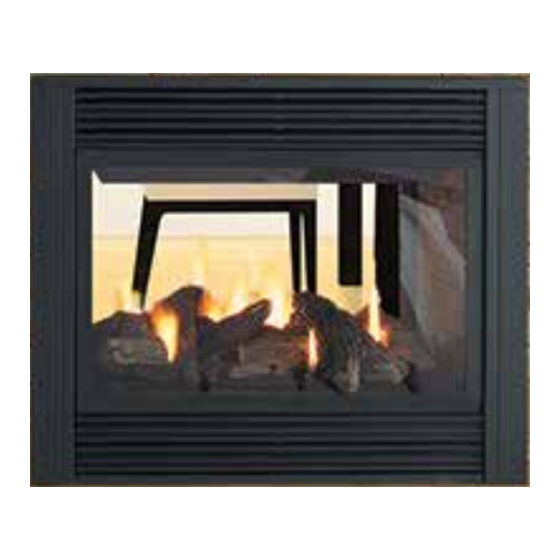
Zero Clearance Direct Vent Gas Fireplace
STYLE
See Thru
P121-NG10 Natural Gas
Pier
P131-NG10 Natural Gas
WARNING
FIRE OR EXPLOSION HAZARD
Failure to follow safety warnings exactly could result in serious
injury, death, or property damage.
- Do not store or use gasoline or other flammable vapors and liquids in the vicinity of this or any other
appliance.
- WHAT TO DO IF YOU SMELL GAS
•
Do not try to light any appliance.
• Do not touch any electrical switch: do not use any phone in your building.
Leave the building immediately.
• Immediately call your gas supplier from a neighbour's phone. Follow the gas supplier's
instructions.
• If you cannot reach you gas supplier, call the fire department.
- Installation and service must be performed by a qualified installer, service agency or the gas supplier.
Tested by:
919-498
FPI FIREPLACE PRODUCTS INTERNATIONAL LTD. 6988 Venture St., Delta, BC Canada, V4G 1H4
P121 / P131
MODEL
P121-LP10 Propane
P131-LP10 Propane
Installer: Please complete the details on the back cover
and leave this manual with the homeowner.
Homeowner: Please keep these instructions for future reference.
Owners &
Installation Manual
www.regency-fire.com
12.17.14
Advertisement
Table of Contents

Related Manuals for Regency P121-NG10


Summary of Contents for Regency P121-NG10
- Page 1 Owners & Zero Clearance Direct Vent Gas Fireplace Installation Manual www.regency-fire.com STYLE MODEL See Thru P121-NG10 Natural Gas P121-LP10 Propane Pier P131-NG10 Natural Gas P131-LP10 Propane WARNING FIRE OR EXPLOSION HAZARD Failure to follow safety warnings exactly could result in serious injury, death, or property damage.
- Page 2 The model P121 / P131 has been approved by Intertek for both safety and efficiency. As it also bears our own mark, it promises to provide you with economy, comfort and security for many trouble free years to follow. Please take a moment now to acquaint yourself with these instructions and the many features of your Regency Fireplace.
-
Page 3: Manufactured Mobile Home Requirements
MANUFACTURED MOBILE HOME REQUIREMENTS INFORMATION FOR MOBILE/MANUFACTURED HOMES AFTER FIRST SALE This Regency product has been tested and listed by Intertek as a Direct Vent Wall Furnace to the following standards: VENTED GAS ® FIREPLACE HEATERS CAN/CGA-2.17-M91, and ANSI Z21.88-2014 • CSA 2.33-2014 and GAS-FIRED APPLIANCES FOR USE AT HIGH ALTITUDES CAN/CGA 2.17-M91. -
Page 4: Table Of Contents
Pilot Adjustment ............28 Fan Replacement ............41 Gas Pipe Pressure Testing ..........28 P121-10 (See Thru) Main Assembly ......42 P131-10 (Pier) Main Assembly ........43 P121-10/P131-10 Burner Assembly & Log Set ...44 Warranty ..............47 Regency P121-10/P131-10 Zero Clearance Direct Vent Gas Fireplace ®... -
Page 5: Copy Of Safety Decal
APPAREIL FONCTIONNANT AU NATURAL GAZ This appliance must be installed in accordance with local codes, if any; if NATURAL GAS: Model/Modele: P121-NG10/ P131-NG10 none, follow the National Fuel Gas Code, ANSI Z223.1, or Natural Gas CONCU POUR ETRE POELE: and Propane Installation Code, CSA B149.1. -
Page 6: For The State Of Massachusetts Only
(e) A copy of all installation instructions for all Product Approved side wall horizontally vented gas fueled equipm ent, all venting instructions, all parts lists for venting instructions, and/or all venting design instructions shall remain with the appliance or equipment at the completion of the installation. Regency P121-10/P131-10 Zero Clearance Direct Vent Gas Fireplace ®... -
Page 7: Dimensions
P121-10 See Thru Note: These units are non-load bearing. Regency P121-10/P131-10 Zero Clearance Direct Vent Gas Fireplace ®... - Page 8 P131-10 Pier Note: These units are non-load bearing. Regency P121-10/P131-10 Zero Clearance Direct Vent Gas Fireplace ®...
-
Page 9: Important Message
T H E B A R R I E R S H A L L B E R E P L A C E D SERIOUS HOUSE FIRE. WITH THE MANUFAC TURER'S BARRIER FOR THIS APPLIANCE. Regency P121-10/P131-10 Zero Clearance Direct Vent Gas Fireplace ®... -
Page 10: General Safety Information
15-20 min. to stabilize. other reproductive harm. CAUTION: Any alteration to the product that causes sooting or carboning that results in damage is not the responsibility of the manufacturer. 10 | Regency P121-10/P131-10 Zero Clearance Direct Vent Gas Fireplace ®... -
Page 11: Locating Your Gas Fireplace
Have a qualified inspector, dealer, or installer review your plans before installation. Note: For Exterior Vent Termination Locations see section "Exterior Vent Termination Locations." Regency P121-10/P131-10 Zero Clearance Direct Vent Gas Fireplace ®... -
Page 12: Clearances
"heat resistant" or the paint may discolour. * If the 3" (76mm) metal extension trim is removed it must be replaced with a 8" (203mm) non- combustible material. 12 | Regency P121-10/P131-10 Zero Clearance Direct Vent Gas Fireplace ®... -
Page 13: Framing And Finishing
B 42-1/2"(1080mm) C 46-3/4"(1187mm) 45" (1143mm) minus 1X the finishing material thickness* * Finish material thickness includes: drywall, ceramic tile, slate, etc. P131-10 - Pier Note: These units are non-load bearing. Regency P121-10/P131-10 Zero Clearance Direct Vent Gas Fireplace ®... -
Page 14: Unit Assembly Prior To Installation
(See "Rigid Pipe Venting 3) Attach the standoff securely to the top with Systems" for more details and exceptions). 4 screws per standoff (on opposite corners). 14 | Regency P121-10/P131-10 Zero Clearance Direct Vent Gas Fireplace ®... -
Page 15: Exterior Vent Termination Locations
* Clearance in accordance with local installation codes and the requirements of the gas supplier 3 feet (91cm) within a height of 15 feet (4.5m) above the meter / regulator assembly 3 feet (91cm) above - if within 10 feet (3m) horizontally Regency P121-10/P131-10 Zero Clearance Direct Vent Gas Fireplace ®... -
Page 16: 4" X 6-5/8" Rigid Pipe Cross Reference Chart
SV4BF TM-4CS Trim Plate-Black 4DT-TP 4DFPB 4DcP SV4LA TM-4TP 16 | Regency P121-10/P131-10 Zero Clearance Direct Vent Gas Fireplace ® Regency Fireplace Products . 6988 Venture St. . Delta, BC . Canada . V4G 1H4 . 604-946-5155 . www.regency-fi re.com... - Page 17 Never allow the vent to run downward - this could cause high temperatures and may present a possible fi re hazard. Regency Fireplace Products . 6988 Venture St. . Delta, BC . Canada . V4G 1H4 . 604-946-5155 . www.regency-fi re.com...
-
Page 18: Venting Arrangement - Horizontal Terminations
8) plated screws (8) 9) screws #8 x 1-1/2" drill point, stainless steel (4) Notes: 1) Liner sections should be continuous without any joints or seams. 2) Only Flex pipe purchased from Regency may be used for Flex installations. ® Regency Direct Vent System (Flex) is only approved for horizontal terminations. -
Page 19: Rigid Pipe Venting Systems
Metal Products Ameri Vent Direct Vent, Security Secure Vent , Selkirk Direct-Temp. AstroCap is a proprietary trademark of FPI Fireplace Products ® International Ltd. Dura-Vent® and Direct Vent are registered and/or proprietary trademarks of Simpson Dura-Vent Co. Inc. Regency P121-10/P131-10 Zero Clearance Direct Vent Gas Fireplace ®... -
Page 20: Rigid Pipe Venting Arrangements
RIGID PIPE VENTING ARRANGEMENTS HORIZONTAL TERMINATIONS REGENCY DIRECT VENT SYSTEM (FLEX) (Propane & Natural Gas) The diagram below shows examples of horizontal termination arrangements using one, two, or three 90 elbows (two 45 elbows equal one 90 elbow). Note:... - Page 21 With the above options, maximum total pipe length if 37 feet with minimum of 5 feet total vertical and maximum 12 feet total horizontal. Please note minimum 1 foot between 90 elbows is required. Diagram 4 Diagram 6 Regency P121-10/P131-10 Zero Clearance Direct Vent Gas Fireplace ®...
- Page 22 Rigid Pipe Adaptor will protrude past the unit 1-1/2" (38mm) when measured from the rear standoffs. Note: A 1-1/4" (32mm) clearance from the elbow must also be maintained. 22 | Regency P121-10/P131-10 Zero Clearance Direct Vent Gas Fireplace ®...
- Page 23 With the above options, maximum total pipe length if 37 feet with minimum of 5 feet total vertical and maximum 12 feet total horizontal. Please note minimum 1 foot between 90 elbows is required. Diagram 11 Regency P121-10/P131-10 Zero Clearance Direct Vent Gas Fireplace ®...
-
Page 24: Horizontal Terminations
Diagram 1. Push the pipe sections recessed into the siding. 24 | Regency P121-10/P131-10 Zero Clearance Direct Vent Gas Fireplace ®... -
Page 25: Vertical Terminations
11/12 to 12/12 1.22 over 12/12 to 14/12 1.52 over 14/12 to 16/12 1.83 over 16/12 to 18/12 2.13 over 18/12 to 20/12 2.29 Diagram 5 over 20/12 to 21/12 2.44 Diagram 3 Regency P121-10/P131-10 Zero Clearance Direct Vent Gas Fireplace ®... -
Page 26: Installation Procedures
2 x 4 or 2 x 6 walls. The liners must slip over the collars a minimum of 1-3/8". INSTALLATION PROCEDURES for Regency AstroCap Direct ® Vent System (Flex) 1) Locate the unit in the framing, rough in the gas. -
Page 27: Conversion From Ng To Lp
16. Check inlet and outlet pressures. 17. Check operation of flame control. Installer Notice: Diagram 1 These instructions must be left 18. Check for proper flame appearance and with the appliance. glow on logs. Regency P121-10/P131-10 Zero Clearance Direct Vent Gas Fireplace ® 919-499 12/03/14... -
Page 28: High Elevation
(High) 3.8"+/- 0.2"w.c. Note: If you have an incorrect flame pattern, off the gas valve, disconnect the hose and contact your Regency dealer for Log Set: Ceramic fibre, 8 per set. ® tighten the screw (clockwise) with a 1/8" flat further instructions. -
Page 29: Wall Mount On / Off Switch Installation
11. Using the two (2) screws provided secure the cover plate to the Receiver. Low Voltage Junction Box Profl ame Receiver J-Box Receiver Slider Switch Wall Plate 10 ft. wire harness with 12 pin connector Diagram 1 Regency P121-10/P131-10 Zero Clearance Direct Vent Gas Fireplace ®... -
Page 30: Log Set Installation
When placing Embers, do not block burner ports as this can cause an incorrect fl ame pattern, Tab on Burner Grate Post carbon deposits and delayed ignition. 30 | Regency P121-10/P131-10 Zero Clearance Direct Vent Gas Fireplace ® Page 1 of 2 01/03/08 918-111c... - Page 31 Repeat step 6 on the opposite side of the burner. on Log 326. Grate Post Completed Log Set Installation: Repeat step 5 on the opposite side of the burner. Regency P121-10/P131-10 Zero Clearance Direct Vent Gas Fireplace ® 01/03/08 918-111c...
-
Page 32: Safety Screen Removal
3. Lift top bracket up and outward to remove as shown in Diagram 2. Diagram 5 Diagram 2 4. Remove safety screen by lifting up and out. 7. To install–reverse steps. Diagram 3 32 | Regency P121-10/P131-10 Zero Clearance Direct Vent Gas Fireplace ®... -
Page 33: Glass Door Removal
3) P131: Remove the 6 screws that secure the Push trim tight glass door and repeat step 2. The Top and Bottom Side Louver or Grill is against magnet. installed the same way. Regency P121-10/P131-10 Zero Clearance Direct Vent Gas Fireplace ®... -
Page 34: Wall Thermostat (Optional)
Note: Preferable if the thermostat is installed on an interior wall. Regency offers an optional programmable thermostat but any 250-750 millivolt rated non- anticipator type thermostat that is CSA, ULC or UL approved may be used. -
Page 35: Wiring Diagrams
CAUTION: Label all wires prior to disconnection when servicing controls. Wiring errors can cause improper and dangerous operation. Terminal Block Location Terminal Block Remove cover to access Terminal Block Regency P121-10/P131-10 Zero Clearance Direct Vent Gas Fireplace ®... -
Page 36: Operating Instructions
Open - Short Blue Proflame Note: Aeration Adjustment should only be video Diagram 2 performed by an authorized Regency ® Installer at the time of installation or Remote shown in Manual Mode on Hi service. 6. The unit will turn on. -
Page 37: Copy Of The Lighting Plate Instructions
Mettre le bouton de commande de gaz en position OFF pour éteindre la veilleuse. Pour économiser le carburant, éteignez la veilleuse quand l’appareil reste longtemps inutilisé. DO NOT REMOVE THIS INSTRUCTION PLATE 919-456 Regency P121-10/P131-10 Zero Clearance Direct Vent Gas Fireplace ®... -
Page 38: First Fire
Open a few windows to ventilate the room for a couple of hours. The glass may Blower: require cleaning. Regency gas appliances use high tech blowers ® to push heated air farther into the room. It is not NOTE: When the glass is cold and the appliance unusual for the fan to make a "whirring"... -
Page 39: Maintenance Instructions
THERMOPILE / a qualified field service person, to ensure that Regency dealer only. Replacement glass is shipped the flow of combustion and ventilation air is not already installed into the door frame. Reinstall as THERMOCOUPLE obstructed. -
Page 40: Removing Valve
6) Remove the burner by removing the 4 screws. 7) Slide the burner assembly away from the 12) Lift the entire assembly out. orifice and lift out. 40 | Regency P121-10/P131-10 Zero Clearance Direct Vent Gas Fireplace ®... -
Page 41: Installing Valve
15) Check the manifold pressure. 16) Reinstall the logs, grate and brick panels as needed. 17) Reinstall the glass doors. 18) Fire up the unit again and check for proper flame appearance. Regency P121-10/P131-10 Zero Clearance Direct Vent Gas Fireplace ®... -
Page 42: P121-10 (See Thru) Main Assembly
204) 360-940 Dec. Grill Front - Black (set) 360-529 Door Assy Side - Tempered 135) 360-069 Heat Shield - Side 205) 948-216 Regency Logo Plate ® 206) 910-171 Fan Axial 115V 5) 363-000 Safety Screen (Each) 146) 360-033 Left Side Door Trim... -
Page 43: P131-10 (Pier) Main Assembly
5) 363-000 Safety Screen (Each) 224) 360-942 Dec. Grill Side - Black (set) 146) 360-035 Finishing Trim 6) 363-002 Horizontal bracket (Each) 225) 948-216 Regency Logo Plate ® 149) 360-122 Magnet Bracket - Corner ** 363-004 Vertical Bracket (Each) 226) 910-142... -
Page 44: P121-10/P131-10 Burner Assembly & Log Set
910-572 Remote receiver 911-127 Remote receiver battery compartment door 910-592 GTMF Remote control Hand held 911-164 Valve wiring harness W840470 Pilot assembly gasket *Not available as a replacement part. 44 | Regency P121-10/P131-10 Zero Clearance Direct Vent Gas Fireplace ®... - Page 45 Regency P121-10/P131-10 Zero Clearance Direct Vent Gas Fireplace ®...
- Page 46 46 | Regency P121-10/P131-10 Zero Clearance Direct Vent Gas Fireplace ®...
-
Page 47: Warranty
It is the general practice of FPI to charge for larger, higher priced replacement parts and issue credit once the replaced component has been returned to FPI and evaluated for manufac- turer defect. The authorized selling dealer is responsible for all in-field service work carried out on your Regency product. FPI will not be liable for results or costs of workmanship from unauthorized service persons or dealers. - Page 48 Dealer Name & Address: ______________________________________________ ___________________________________________________________________ Installer: ___________________________________________________________ Phone #: ___________________________________________________________ Date Installed: ______________________________________________________ Serial No.: __________________________________________________________ Regency and Panorama are trademarks of FPI Fireplace Products International Ltd. Printed in Canada © Copyright 2014, FPI Fireplace Products International Ltd. All rights reserved.
Need help?
Do you have a question about the P121-NG10 and is the answer not in the manual?
Questions and answers