Table of Contents
Advertisement
Owners &
Installation
LISTINGS AND CODE APPROVALS
These gas appliances have been tested in
accordance with AS4553-2000, NZS 5262
and have been certifi ed by the Australian Gas
Association for installation and operation as
described in these Installation and Operating
Instructions.
Your unit should be serviced annually by
an authorised service person.
Zero Clearance Room
Sealed Gas Fireplace
STYLE
See Thru
P121-NG
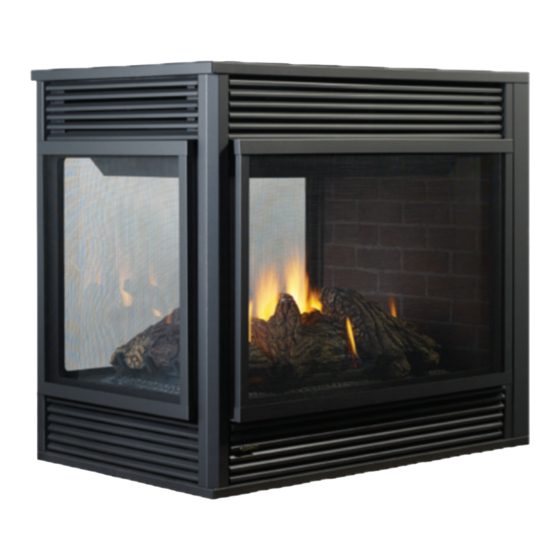
Left Corner
P121LC-NG
Right Corner P121RC-NG
Pier
P131-NG
PLEASE KEEP THESE INSTRUCTIONS
FOR FUTURE REFERENCE
WARNING:
Improper installation, adjustment, altera-
tion, service or maintenance can cause
injury or property damage. Refer to this
manual. For assistance or additional in-
formation consult an authorized installer,
service agency or the gas supplier.
FOR YOUR SAFETY
Do not store or use gasoline or other fl am-
mable vapours and liquids in the vicinity of
this or any other appliance.
Installation and service must be performed
by an authorized installer, service agency or
the gas supplier.
918-536
MODEL
P121-LPG
P121LC-LPG
P121RC-LPG
P131-LPG
FOR YOUR SAFETY
What to do if you smell gas:
Do not try to light any appli-
ance
Do not touch any electri-
cal switch: do not use any
phone in your building.
Immediately call your gas
supplier from a neighbour's
phone. Follow the gas sup-
plier's instructions.
If you cannot reach your
gas supplier, call the fi re
department.
08/26/09
Advertisement
Table of Contents

Related Manuals for Regency P121-NG


Summary of Contents for Regency P121-NG
- Page 1 Owners & Installation Zero Clearance Room Sealed Gas Fireplace STYLE MODEL See Thru P121-NG P121-LPG Left Corner P121LC-NG P121LC-LPG Right Corner P121RC-NG P121RC-LPG Pier P131-NG P131-LPG PLEASE KEEP THESE INSTRUCTIONS FOR FUTURE REFERENCE WARNING: FOR YOUR SAFETY Improper installation, adjustment, altera-...
- Page 2 To the New Owner: Congratulations! ® You are the owner of a state-of-the-art Gas Fireplace by REGENCY . The P121/P121LC/P121RC/ P131 is a hand crafted appliance and has been designed to provide you with all the warmth and charm of a wood fi replace at the fl ick of a switch. The model P121/P121LC/P121RC/P131 has been approved by the Australian Gas Association for both safety and effi...
-
Page 3: Table Of Contents
Glass Door Removal ..........26 Finishing Trim ............27 Louvers and Grills............. 27 Remote Control (optional) ........28 Remote Wall Switch (optional) ......... 28 Wall Thermostat (optional)........28 Wiring Diagram ............29 ® Regency P121/P121LC/P121RC/P131 Zero Clearance Room Sealed Gas Fireplace... -
Page 4: Safety Label
This is a copy of the label that accompanies improved. Check the label on the unit and if each REGENCY P121/P121LC/P121RC/P131 there is a difference, the label on the unit is Zero Clearance Room Sealed Gas Fireplace. -
Page 5: Installation
THEY ARE IN THE SAME ROOM AS INSTRUCTIONS Emissions from burning wood or gas could THE APPLIANCE. contain chemicals known to the State of Cali- fornia to cause cancer, birth defects or other The Regency ® P121/P121LC/P121RC/P131- reproductive harm. GENERAL SAFETY NG or P121/P121LC/P121RC/P131-LPG... -
Page 6: Specifi Cations
INSTALLATION SPECIFICATIONS P121 - See Thru Note: These units are non-load bearing. P131 - Pier ® Regency P121/P121LC/P121RC/P131 Zero Clearance Room Sealed Gas Fireplace... - Page 7 INSTALLATION P121LC - Left Corner Unit Note: These units are non-load bearing. P121RC - Right Corner Unit ® Regency P121/P121LC/P121RC/P131 Zero Clearance Room Sealed Gas Fireplace...
-
Page 8: Locating Your Gas Fireplace
Have a authorized inspector, dealer, or installer C) P121LC - Left Corner review your plans before installation. Note: For Exterior Flue Termination Locations see page 12. D) P121RC - Right Corner ® Regency P121/P121LC/P121RC/P131 Zero Clearance Room Sealed Gas Fireplace... -
Page 9: Clearances
Caution: Ensure the paint that is used on the mantel and the facing is "heat resistant" or the paint may discolour. * If the 3" (76mm) metal extension trim is removed it must be replaced with a 8" (203mm) non-combustible material. ® Regency P121/P121LC/P121RC/P131 Zero Clearance Room Sealed Gas Fireplace... -
Page 10: Framing And Finishing
fl ex, see Flue Clearances, page 9. P121LC - Corner Unit P121 - See Thru P131 - Pier P121RC - Corner Unit Note: These units are non-load bearing. ® Regency P121/P121LC/P121RC/P131 Zero Clearance Room Sealed Gas Fireplace... -
Page 11: Facing And Finishing Requirements
Each direct fl ue gas appliance must use it's own separate fl ue system. Common fl ue systems 3) Attach the standoff securely to the top are prohibited. with 4 screws per standoff (on opposite corners). ® Regency P121/P121LC/P121RC/P131 Zero Clearance Room Sealed Gas Fireplace... -
Page 12: Exterior Flue Termination Locations
(IV) A fl ue terminal of this type shall not be located under a roofed area unless the roofed area is fully open on at least two sides and a free fl ow of air at the appliance is achieved. ® Regency P121/P121LC/P121RC/P131 Zero Clearance Room Sealed Gas Fireplace... -
Page 13: Flueing: Direct Vent System (Flex)
9) screws #8 x 1-1/2" drill point, stainless steel (4) Notes: 1) Liner sections should be continuous without any joints or seams. ® 2) Only Flex pipe purchased from Regency may be used for Flex installations. Regency ® Direct Vent System (Flex) is only approved for horizontal terminations. -
Page 14: Flueing: Simpson Dura-Vent Direct Vent Gs
Direct Vent GS Dura-Vent® and Direct Vent GS are registered and/or proprietary trademarks of Simpson Dura-Vent Co. Inc. SIMPSON DURA-VENT FLUEING COMPONENTS LIST All Simpson Dura-Vent components are available directly from Regency ® Part # Description Part # Description Part # Description 981 Snorkel - 36"... -
Page 15: Flueing Arrangements Horizontal Terminations
6 feet total vertical and maximum 17 feet total horizontal. Please note minimum 1 foot between 90 elbows is required. Diagram 1 Diagram 2 Please note the minimum centerline for basic install shown above. ® Regency P121/P121LC/P121RC/P131 Zero Clearance Room Sealed Gas Fireplace... - Page 16 With the above options, maximum total pipe length if 37 feet with mini- mum of 5 feet total vertical and maximum 12 feet total horizontal. Please note minimum 1 foot between 90 elbows is required. Diagram 4 Diagram 6 ® Regency P121/P121LC/P121RC/P131 Zero Clearance Room Sealed Gas Fireplace...
-
Page 17: Vertical Terminations
4 feet total vertical and maximum 8 feet total horizontal. Please note minimum 1 foot between 90 elbows is required. 45° Elbow Rigid Pipe Adapter Part # 510-994 Diagram 7 Diagram 8 ® Regency P121/P121LC/P121RC/P131 Zero Clearance Room Sealed Gas Fireplace... - Page 18 With the above options, maximum total pipe length if 37 feet with mini- mum of 5 feet total vertical and maximum 12 feet total horizontal. Please note minimum 1 foot between 90 elbows is required. Diagram 11 ® Regency P121/P121LC/P121RC/P131 Zero Clearance Room Sealed Gas Fireplace...
-
Page 19: Flueing - Dura-Vent Horizontal Installations
Diagram 1. Push the pipe sections pipe to the fl ue termination, slide the Wall allow the fl ue to run downward. This completely together, then twist-lock Thimble (Part # 942) over the fl ue pipe. ® Regency P121/P121LC/P121RC/P131 Zero Clearance Room Sealed Gas Fireplace... -
Page 20: Flueing - Dura-Vent Vertical Termination
11/12 to 12/12 1.22 over 12/12 to 14/12 1.52 over 14/12 to 16/12 1.83 over 16/12 to 18/12 2.13 Diagram 5 over 18/12 to 20/12 2.29 over 20/12 to 21/12 2.44 Diagram 3 ® Regency P121/P121LC/P121RC/P131 Zero Clearance Room Sealed Gas Fireplace... -
Page 21: System (Flex)
2 x 4 or 2 x 6 walls. The liners must slip over the collars a minimum of 1-3/8". INSTALLATION PROCEDURES ® for Regency AstroCap Direct Flue System (Flex) 1) Locate the unit in the framing, rough in the gas. Locate the centerline of the ter- mination and mark wall accordingly. -
Page 22: Converion To Lpg
Allen wrench into the hexagonal key-way of 6) Pull off the pilot the screw cap to expose (Fig. 2), rotate it the pilot orifi ce. counter-clockwise until it is free and extract it. Fig.2 ® Regency P121/P121LC/P121RC/P131 Zero Clearance Room Sealed Gas Fireplace... - Page 23 17) Verify that if the conversion is from NG to LPG, the screw must be re-assembled with the red o-ring visible (Fig. 5). LPG Configuration Red o-ring visible Fig.5 18) Re-assemble the black protection cap (Fig. 6). Fig. 6 ® Regency P121/P121LC/P121RC/P131 Zero Clearance Room Sealed Gas Fireplace...
-
Page 24: System Data
For 0 to 4500 feet altitude Note: If you have an incorrect fl ame pat- screwdriver. Note: Screw should be snug, Burner Inlet Orifi ce Sizes: tern, contact your Regency ® dealer but do not over tighten. Pilot Orifi ce LPG for further instructions. -
Page 25: Log Set Installation
3) Place Log 327 on the front left side of the burner. Position the right end of the log in between the two tabs and the left end of the log into the grate post. Tab on Burner Grate Post ® Regency P121/P121LC/P121RC/P131 Zero Clearance Room Sealed Gas Fireplace... - Page 26 Log onto the second grate post from the left. Ensure that the log fi ts into a pin that is on Log 326. Place Log 329 onto pin. Grate Post ® Regency P121/P121LC/P121RC/P131 Zero Clearance Room Sealed Gas Fireplace...
-
Page 27: Glass Door Removal
Remove the 6 screws that secure the glass Push trim tight door and repeat step 2. against magnet. The Top and Bottom Side Louver or Grill is installed the same way. ® Regency P121/P121LC/P121RC/P131 Zero Clearance Room Sealed Gas Fireplace... -
Page 28: Remote Control (Optional)
A wall thermostat may be installed if desired, 1) Run the supplied 4.5m of wire through the ® Use the Regency Remote Control Kit approved connect the wires as per the wiring diagram. back gas inlet opening. Be careful not to for this unit. -
Page 29: Wiring Diagram
CAUTION: Label all wires Terminal Block Location prior to disconnection when servicing controls. Wiring er- rors can cause improper and dangerous operation. Terminal Block Remove cover to ac- cess Terminal Block ® Regency P121/P121LC/P121RC/P131 Zero Clearance Room Sealed Gas Fireplace... -
Page 30: Operating Instructions
Never operate the ap- DO NOT BURN THE APPLIANCE pliance with the glass removed. Blower: WITHOUT THE GLASS FRONT IN Regency ® gas appliances use high tech blowers PLACE. 5) Verify that the fl ueing and cap are unob- to push heated air farther into the room. -
Page 31: Lighting Plate Instructions
Force or ® resistant paint. Regency uses StoveBright B)BEFORE LIGHTING smell all around attempted repair may result in a fire Paint - Metallic Black #6309. -
Page 32: Log Replacement
fi ttings. It may be caused by having excessive lateral runs, 4) Remove the grate by lifting straight up. too many elbows, and exterior portions of the Your Regency ® fi replace is supplied with high system being exposed to cold weather. -
Page 33: Installing Valve
16) Reinstall the logs, grate and brick panels as needed. 17) Reinstall the glass doors. 18) Fire up the unit again and check for proper fl ame appearance. 12) Lift the entire assembly out. ® Regency P121/P121LC/P121RC/P131 Zero Clearance Room Sealed Gas Fireplace... -
Page 34: Parts List
204) 360-940 Dec. Grill Front - Black (set) 17) 360-086 Gasket - Relief Door 24) * Relief Door Assembly ® 205) 948-216 Regency Logo Plate 206) 910-172 Fan Axial 240V 32) 902-296 Brick Panel - Base - Front 207) 910-142 Thermodisc... - Page 35 Dec. Grill Side - Black (set) 150) 360-123 Magnet Bracket - Front 360-529 Door Assy Side - Tempered 151) 904-258 Magnet ® 225) 948-216 Regency Logo Plate 360-948 Door Assy Side- Ceramic 226) 910-142 Thermodisc 171) 360-920 Louver Front - Black (set) (Optional)
- Page 36 224) 360-942 Dec. Grill Side - Black (set) 146) 360-035 Finishing Trim - Left Side 360-538 Door Assy Front - Ceramic (Optional) 225) 948-216 Regency ® Logo Plate 149) 360-122 Magnet Bracket - Corner 226) 910-142 Thermodisc 150) 360-123 Magnet Bracket - Front...
- Page 37 Door Assy Front - Ceramic 224) 360-942 Dec. Grill Side - Black (set) 141) 360-031 Column Finishing Trim (Optional) 146) 360-035 Finishing Trim 225) 948-216 Regency ® Logo Plate 360-529 Door Assy Side - Tempered 226) 910-142 Thermodisc 360-539 Door Assy Side - Ceramic...
- Page 38 Orifi ce #31 - NG 936-170 Orifi ce Gasket 83) 910-073 Spark Generator Battery Holder 84) 910-074 Spark Generator Switch c/w Wire 90) 910-386 Thermocouple 91) 910-341 Thermopile *Not available as a replacement part. ® Regency P121/P121LC/P121RC/P131 Zero Clearance Room Sealed Gas Fireplace...
-
Page 39: Warranty
The warranty does not extend to any part or parts which show evidence of misuse or abuse, neglect, accident, lack of maintenance, or improper installation. ® Products made by other manufacturers and used in conjunction with the operation of this appliance without authorization from Regency , may nullify your warranty on this product.
Need help?
Do you have a question about the P121-NG and is the answer not in the manual?
Questions and answers