Sub-Zero 424 Installation Manual
Hide thumbs
Also See for 424:
- Use & care manual (24 pages) ,
- Specifications (12 pages) ,
- Quick start (2 pages)
Table of Contents
Advertisement
Advertisement
Chapters
Table of Contents

Related Manuals for Sub-Zero 424


Summary of Contents for Sub-Zero 424
-
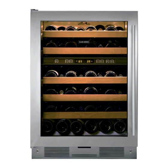
Page 1: Wine Storage
INSTALLATION GUIDE Wine Storage... -
Page 2: Table Of Contents
To ensure the safe and efficient installation of Sub-Zero equipment, please take note of the following types of Models 424 and 424FS Installation ....4 highlighted information throughout this guide: Models 427 and 427R Installation . -
Page 3: Wine Storage Equipment
Important product information, including the model and serial number of your unit are listed on the product rating plate. For models 424 and 424FS, the rating plate is located on the underside of the top wall. For models 427, 427R and WS-30, it is attached to the underside of the... -
Page 4: Models 424 And 424Fs Installation
Models 424 and 424FS Installation Models 424 and 424FS OVERALL DIMENSIONS " 24" " " (606) (610) (616) (625) 34" " (864) (868) 4" 4" (102) (102) " " (645) (645) " " (60) (60) MODEL 424 MODEL 424FS Door swing clearances are based on stainless steel door and... - Page 5 OPENING Make sure that the finished rough opening where the DEPTH model 424 wine storage unit is to be installed is properly prepared. Refer to the illustration. The floor under the unit must be level with the surrounding finished floor.
-
Page 6: Electrical Requirements
Models 424 and 424FS Installation Electrical Requirements For models 424 and 424FS, the electrical supply should Electrical Requirements be located within the shaded area shown in the illustra- Power Supply 115 V AC, 60 Hz tion. Follow the National Electrical Code and local codes... - Page 7 424 and 424FS. A minimum of 36" Reverse the procedure to reinstall the shelf. (914) of lead wire should be provided for each contact, Use an appliance dolly to move the wine storage unit.
-
Page 8: Model 424
Refer to the illustration below. A smaller metal ‘countertop’ bracket is also provided with the model 424, for installations that need to be modified to provide a secure surface for attaching the bracket. This ANTI-TIP BRACKET bracket will secure the front of the unit to the underside of the countertop, above the unit. - Page 9 Models 424 and 424FS Installation subzero.com Anti-Tip Bracket Installation WOOD FLOOR APPLICATIONS INSTALL CONCRETE WEDGE ANCHORS: Use the four #12 x 2 " wood screws and the four " 1) Drill a " (10) diameter hole any depth exceeding the flat washers provided.
- Page 10 After the unit is in position, available through your authorized Sub-Zero dealer, or call the alarm wiring can be completed from the front. Sub-Zero at 800-222-7820. You can also visit our website at subzero.com. Pre-level the wine storage unit before sliding it into position.
- Page 11 If a home alarm system is to be installed on the wine For model 424, the countertop bracket should be used storage unit, the connections should be made using the to make a solid installation. Refer to the illustration on logic supplied with the alarm specifications.
- Page 12 Kickplate Installation Door Panel—Model 424 Once the unit is leveled and wiring connections made, Model 424 is offered in two design applications; stainless the kickplate can be installed. Use the two #10 x " steel (/S) and overlay (/O). Each of these designs have a stainless steel screws that are provided with the kickplate.
-
Page 13: Overlay Panel 30" (762) 9
Use as many screws as necessary to attached first. hold the door panel in place properly. Decorative panels are attached to the model 424 door IMPORTANT NOTE: After the first three or four mounting using #8 x "... - Page 14 Models 424 and 424FS Installation Overlay Door Panel—Model 424 IMPORTANT NOTE: Install screws in all the mounting holes in the door frame. The nature of the door panel with The wine storage unit door is made with a sealed a narrow outer rim and no connecting center member double wall tempered glass core.
- Page 15 IMPORTANT NOTE: When you have completed the instal- installed and leveled before door hinge adjustments can lation of the model 424 or 424FS wine storage unit, refer be made. to page 54 for an installation checklist and page 55 for service information.
-
Page 16: Models 427 And 427R Installation
Models 427 and 427R Installation Models 427 and 427R OVERALL DIMENSIONS 27" 24" 27" 24" (686) (610) (686) (610) 14" 14" (356) (356) " " (21) (21) " " (1995) (1995) 80" 80" (2032) (2032) OPENING OPENING " HEIGHT HEIGHT (10) "... - Page 17 Models 427 and 427R Installation subzero.com Models 427 and 427R Installation Refer to the previous page for overall dimensions and OPENING DIMENSIONS door swing clearances for models 427 and 427R. TOP VIEW Make sure that the finished rough opening where the wine storage unit is to be installed is properly prepared.
- Page 18 Models 427 and 427R Installation Electrical Requirements For models 427 and 427R, the electrical supply should be Electrical Requirements located within the shaded area shown in the illustration. Power Supply 115 V AC, 60 Hz Follow the National Electrical Code and local codes and Circuit Breaker 15 amp ordinances when installing the receptacle.
- Page 19 Models 427 and 427R Installation subzero.com Electrical Requirements Unpacking and Moving Uncrate the unit, remove its wood base and discard the HOME ALARM SYSTEM shipping bolts that hold the wood base to the bottom of If a home alarm system is to be used, refer to wiring the unit.
- Page 20 Models 427 and 427R Installation Anti-Tip Bracket Installation An anti-tip bracket and hardware is provided with the wine WOOD FLOOR APPLICATIONS storage unit. The anti-tip bracket must be installed on a Use the six #12 x 2 " wood screws and the six "...
- Page 21 25 foot-pounds of torque. into position. The dual installation heater kit and additional instructions is available through your authorized Sub-Zero dealer, or call Sub-Zero at 800-222-7820. You can also Always wear safety glasses and use other necessary visit our website at subzero.com.
- Page 22 After the unit is in position, the alarm available through your authorized Sub-Zero dealer, or call wiring can be completed from the front. Sub-Zero at 800-222-7820. You can also visit our website Pre-level the wine storage unit before rolling into position. at subzero.com.
- Page 23 Models 427 and 427R Installation subzero.com Leveling Install Molding Level the unit by turning the front leveling legs clockwise The decorative white molding strips for the top and sides to raise the unit, or counterclockwise to lower it. To assist of models 427 and 427R can be snapped into place as you in adjusting the front leveling legs up or down, use a shown in the illustrations below.
- Page 24 Models 427 and 427R Installation Wiring Connections Before the kickplate/grille is installed, all necessary wiring IMPORTANT NOTE: If you are not responsible for alarm connections in the compressor compartment should be system connection, this information should be supplied to completed. the home security system contractor.
- Page 25 BRACKET If you have questions, contact your authorized Sub-Zero dealer or cabinet supplier. Additional panel information can be found in the Sub-Zero design guide, or visit our website at subzero.com. Kickplate/grille installation. A solid panel cannot be installed over the glass door,...
- Page 26 20 lbs (9 kg). Refer to the wine The stainless steel panel is mounted to the door by storage section of the Sub-Zero design guide for addi- passing the #8–32 x " screws provided, through holes in tional panel information.
- Page 27 This is to centered on the small groove in the front of the door accommodate the Sub-Zero accessory handles and frame and the drill passes squarely through the frame. provide for easy attachment of the handle through the If you are inexperienced with drilling, fasten the handle door frame.
- Page 28 Models 427 and 427R Installation Model 427R Drawer Panels IMPORTANT NOTE: Drawer panels for model 427R must To help with proper placement of drawer panels, examine be a minimum of " (16) thick and cannot exceed 12 lbs the lower panel mounting bracket and determine which (5 kg) for each panel.
- Page 29 427, 427R or integrated units together. The kit is available through your authorized Sub-Zero dealer, or Complete the Installation call Sub-Zero at 800-222-7820. You can also visit our website at subzero.com. IMPORTANT NOTE: When you have completed the instal-...
-
Page 30: Model Ws-30 Installation
110°. A 90° door stop is shipped with the unit. The handle depth reflects a tubular or pro handle. For additional infor- HEIGHT DIMENSIONS ± 1 " (13) " (606) 4" (102) mation, refer to the full-scale templates in the Sub-Zero design guide. " (606) 17" (432) " (796) "... - Page 31 Torx drive screwdriver set different for the flush inset application, whether you are • Level—2' (.6 m) and 4' (1.2 m) recommended using custom panels or Sub-Zero accessory flush inset panels. • Appliance dolly able to support 700 lbs (317 kg) and...
- Page 32 Model WS-30 Installation Standard Installation Opening Dimensions Framed, Overlay and Stainless Steel Models TOP VIEW 24" (610) OPENING DEPTH 24" " " (610) (746) OPENING DEPTH (2127) OPENING WIDTH OPENING HEIGHT SIDE VIEW FRONT VIEW IMPORTANT NOTE: If two units are installed side by side, refer to page 34 for dual standard installations.
- Page 33 Model WS-30 Installation subzero.com Flush Inset Installation Opening Dimensions TOP VIEW 24" " (610) " 24" (610) TOP VIEW (665) DEPTH (665) OPENING TO CLEAT FLUSH OUTLINE OF FLUSH DEPTH INSET CLEAT " UNIT WITH INSET TO CLEAT DEPTH " (32) CLEAT (19)
- Page 34 Model WS-30 Installation Dual Standard Installation Opening Dimensions Framed, Overlay and Stainless Steel Models TOP VIEW 24" (610) OPENING DEPTH 24" " (610) (2127) OPENING DEPTH OPENING WIDTH OPENING HEIGHT SIDE VIEW FRONT VIEW IMPORTANT NOTE: A dual installation kit will be required for Opening Widths this installation.
- Page 35 Model WS-30 Installation subzero.com Dual Flush Inset Installation Opening Dimensions TOP VIEW " 24" (610) DEPTH " 24" (665) (610) TOP VIEW FLUSH TO CLEAT (665) OPENING INSET FLUSH DEPTH " CLEAT DEPTH INSET TO CLEAT (32) TWO UNITS WITH CLEAT DEPTH "...
- Page 36 Model WS-30 Installation Electrical Requirements For model WS-30, the electrical supply should be located Electrical Requirements within the shaded area shown in the illustration. Follow the Power Supply 115 V AC, 60 Hz National Electrical Code and local codes and ordinances Circuit Breaker 15 amp when installing the receptacle.
- Page 37 Model WS-30 Installation subzero.com Unpack the Unit Grille Removal Uncrate the unit and inspect for any damages. Remove In order to prevent damage to the grille and to access the the wood base and discard the shipping bolts and power cord, the top grille assembly should be removed brackets that hold the wood base to the bottom of the prior to moving the unit.
- Page 38 Model WS-30 Installation Anti-Tip Bracket Installation IMPORTANT NOTE: For either wood or concrete floor applications, if the #12 x 2 " screws do not hit a wall To prevent the unit from tipping forward and provide stud or the wall plate in any of the back holes of the a stable installation, the unit must be secured in place brackets, use the provided #8–18 x 1 "...
- Page 39 Model WS-30 Installation subzero.com Anti-Tip Bracket Installation CONCRETE FLOOR APPLICATIONS INSTALL CONCRETE WEDGE ANCHORS: After properly locating the anti-tip brackets in the rough 1) Drill a " (10) diameter hole any depth exceeding the opening, drill pilot holes " (5) diameter maximum in the minimum embedment.
- Page 40 Model WS-30 Installation Position the Unit Level the Unit Use an appliance dolly to move the unit near the rough Once the unit is in position, extend the front leveling legs opening. Model WS-30 is equipped with rollers, so it can down by turning the legs clockwise to adjust the height.
- Page 41 Model WS-30 Installation subzero.com Door Adjustment The door of the model WS-30 can be adjusted in three DOOR HEIGHT ADJUSTMENT ways: In and out, side to side tilt, and up and down. To adjust a left-hinge door; using a " allen wrench, turn Regardless of the adjustment being made, start by slightly the bolt clockwise to raise the door and counterclockwise loosening the two upper hinge bolts on the upper hinge...
- Page 42 Model WS-30 Installation Anchoring Home Alarm Connections After door and side panels have been installed, the unit If a home alarm system is to be installed on the wine has been leveled and door adjustment completed, anchor storage unit, the connections should be made using the the wine storage unit to the opening.
- Page 43 Sub-Zero look. grille. Additional 90° door stop kits are available through your authorized Sub-Zero dealer. To obtain local dealer IMPORTANT NOTE: For overlay models, there are two information, visit the showroom locator section of our design applications—overlay and flush inset.
- Page 44 Additional panel design information can be trim molding. Insert a screwdriver tip into the top corner found in the Sub-Zero design guide and on our website, slot on the handle side and pop out the trim molding. subzero.com.
- Page 45 " (6) total thickness. Check the location of offset when you’re using specific routing for the grip area only. Refer to the Sub-Zero design guide for a full-scale template of the standard full-length handle and panel. Use this template to lay out your panel design for finger clearance when a standard full-length handle is used.
-
Page 46: Overlay Panel 30
Additional panel design infor- sions, standard for all models. mation can be found in the Sub-Zero wine storage design Install the handle hardware before inserting the panel. We guide and on our website, subzero.com. - Page 47 " " (740) (211) restrict the air flow to the compressor area and cause Backer Panel " " (756) (227) problems with the operation of the Sub-Zero unit. WINDOW Cut-Out " " (597) (1607) Location " (83) A solid panel cannot be installed over the glass door, as this may cause moisture to form behind the panel.
- Page 48 Additional panel design minimum reveals must be kept on all sides to ensure information can be found in the Sub-Zero design guide proper door opening and sufficient cooling of the unit. and on our website, subzero.com.
-
Page 49: Grille Wh
The flush inset decorative panel cannot be any larger GRILLE or it may restrict the air flow to the compressor area Flush Inset Panel 31" " (787) (235) and cause problems with the operation of the Sub-Zero Spacer Panel " " (740) (211) unit. Backer Panel "... -
Page 50: Model
Contact your authorized Sub-Zero dealer for the proper components and installation instructions. For For additional information on panel reveals, visit the speci- questions relative to the installation, call Sub-Zero at fication library section of our website, subzerotrade.com. -
Page 51: Flush Inset Panel Spacer Panel Backer Panel
Backer Panel " " (756) (227) Dual flush inset panels and dual installation kits are avail- WINDOW able through your authorized Sub-Zero dealer. Refer to the Cut-Out 23" " (584) (1581) illustration and chart for dual flush inset panel specifica- Location "... - Page 52 DOOR " " Do not exceed the flush inset decorative panel dimen- SIDE VIEW SIDE VIEW sions. Exceeding dimensions could cause damage to the panels and the Sub-Zero unit. Illus. C Illus. D DOOR / Panel Offsets Illus. DRAWER WS-30...
-
Page 53: Cut-Out
Routing will be necessary for the side panel to fit flush Sub-Zero dealer. Refer to instructions included with the against the side of the unit. Refer also to the routing detail side panel kit when installing these side panels. To obtain illustration. -
Page 54: Installation Checklist
Is the kickplate installed? Installation Checklist Has the drain pan been installed properly (WS-30)? The importance of the installation of the Sub-Zero wine storage unit cannot be overemphasized. Proper installa- Are panels attached securely and properly aligned? tion is the responsibility of the selling dealer or installer. -
Page 55: Service Information
Models 427, 427R and WS-30. The information and images in this guide are the copyright property of Sub-Zero, Inc. Neither this guide nor any information or images contained herein may be copied or used in whole or in part without the express written permission of Sub-Zero, Inc. ©Sub-Zero, Inc. all rights reserved. - Page 56 SUB-ZERO, INC. P. O. BOX 44848 MADISON, WI 53744 SUBZERO.COM 800.222.7820 7011714 REV-A 7/ 2010...
Need help?
Do you have a question about the 424 and is the answer not in the manual?
Questions and answers