Table of Contents
Advertisement
Quick Links
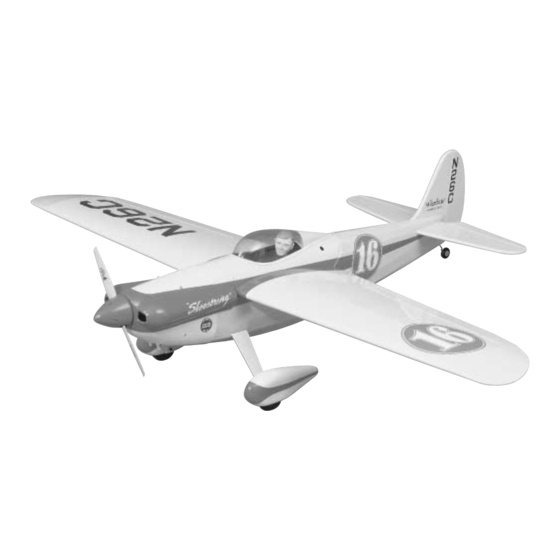
A. R. F.
Almost Ready to Fly
Wingspan: 61.5" [1,560mm]
Wing area: 712.5" [46 sq dm]
Weight: 7 lbs [3,630g]
Wing loading: 25.9 oz/sq ft [79 g/sq cm]
Length: 53" [1,345mm]
Radio: 4-ch (five servos)
Engine: .61 two-stroke, .91 four-stroke [10cc 2-stroke, 15cc 4-stroke]
Great Planes
®
Model Manufacturing Co. guarantees this kit to be free from defects in both material and workmanship at the date of
purchase. This warranty does not cover any component parts damaged by use or modification. In no case shall Great Planes' liability
exceed the original cost of the purchased kit. Further, Great Planes reserves the right to change or modify this warranty without notice.
In that Great Planes has no control over the final assembly or material used for final assembly, no liability shall be assumed nor
accepted for any damage resulting from the use by the user of the final user-assembled product. By the act of using the user-assembled
product, the user accepts all resulting liability.
If the buyer is not prepared to accept the liability associated with the use of this product, the buyer is advised to return this
kit immediately in new and unused condition to the place of purchase.
READ THROUGH THIS MANUAL BEFORE
STARTING CONSTRUCTION. IT CONTAINS
IMPORTANT WARNINGS AND INSTRUCTIONS
CONCERNING THE ASSEMBLY AND USE OF
THIS MODEL.
© Copyright 2001
INSTRUCTION MANUAL
WARRANTY
1610 Interstate Drive Champaign, IL 61822
(217) 398-8970, Ext 2
airsupport@greatplanes.com
GPMZ0253 for GPMA1325 V1.0
Advertisement
Table of Contents

Related Manuals for GREAT PLANES Shoestring ARF


Summary of Contents for GREAT PLANES Shoestring ARF
-
Page 1: Instruction Manual
Further, Great Planes reserves the right to change or modify this warranty without notice. In that Great Planes has no control over the final assembly or material used for final assembly, no liability shall be assumed nor accepted for any damage resulting from the use by the user of the final user-assembled product. -
Page 2: Table Of Contents
IMPORTANT SAFETY PRECAUTIONS Check the Control Directions ...........19 Set the Control Throws.............19 1. The Shoestring ARF should not be considered a toy, but rather a sophisticated, working model that functions very Balance the Model (C.G.)..........20 much like a full-size airplane. Because of its performance Balance the Model Laterally..........21... -
Page 3: Additional Items Required
#3217 (SLIG2217) Pitts Style (for O.S. .61 SF, FP, FX). To you join the AMA (Academy of Model Aeronautics). AMA use these mufflers, a portion of the included Great Planes membership is required to fly at AMA sanctioned clubs. 60-120 engine mount will have to be trimmed to There are over 2,500 AMA chartered clubs across the accommodate the muffler. -
Page 4: Hardware And Accessories
ORDERING REPLACEMENT PARTS To order replacement parts for the Great Planes Shoestring ARF, use the order numbers in the Replacement Parts List that follows. Replacement parts are available only as listed. Not all parts are available separately (an aileron cannot be purchased separately, but is only available with the wing kit). -
Page 5: Kit Contents
If any parts are missing or are not of acceptable quality, or if you need assistance with assembly, contact Great Planes Product Support. When reporting defective or missing parts, use the part names exactly as they are written in the Kit Contents list on this page. -
Page 6: Preparations
PREPARATIONS 1. If you have not done so already, remove the major parts of the kit from the box (wings, fuse, wheel pants, cowl, tail parts, etc.) and inspect them for damage. If any parts are damaged or missing, contact Product Support at the address or telephone number listed on the front cover. -
Page 7: Join The Wing
mounting location. Saturate the holes with thin CA, wipe away residual CA and allow to fully harden. Mount the aileron control horn to the aileron with two #2 x 1/2" screws. 6. Apply six drops of thin CA to the top and bottom of each hinge. -
Page 8: Build The Fuselage
3. Prepare 1/2 oz. of 30-minute epoxy. Add 1/2 oz. of BUILD THE FUSELAGE microballoons. Working quickly, thoroughly coat the inside of both wing halves where the joiner fits and one half of the joiner with the epoxy and microballoons mixture. Making Mount the Wing certain the joiner is upright, insert the coated end into one of the wing halves. -
Page 9: Mount The Stab And Fin
the covering from the slots for the stab and fin 3/32" from the edge, thus leaving a flap that can be ironed to the stab and fin after gluing them into position. ROUND 6. Use a hobby knife with a sharp #11 blade to cut the covering from the wing where the wing bolt plate will fit. - Page 10 the top and bottom of the stab. (Disregard the elevators, fin and rudder in the photo - they should not be mounted to the model yet.) 8. Remove the stab from the fuse. Use a sharp #11 hobby knife or use the Expert Tip that follows to cut the covering from the stab along the lines you marked.
- Page 11 12. Drill a 1/8" hole through the LE of both elevators at the marks you made. Use a Great Planes Groove Tube (GPMR8140) or a 1/8" brass tube sharpened on the end to cut a groove in the LE of the elevators to accommodate the joiner wire.
-
Page 12: Mount The Wheel Pants And Landing Gear
Refer to these photos for the following two steps. 17. The same as the elevators, drill a 3/32" hole in the rudder for the tail gear wire and cut a groove to accommodate the bearing. 18. Apply petroleum jelly to the tail wheel bearing where the wire passes through. -
Page 13: Finish The Cockpit
7. Use a metal saw or a high-speed rotary tool with a 13. Without moving the wheel pants, mark the locations reinforced cut-off wheel to cut 5/16" from one of the bolt-on of the holes in the landing gear onto the wheel pants. axles. - Page 14 8. Wash the canopy in warm, soapy water. Glue the canopy to the cockpit with R/C-56 Canopy Glue (JOZR5007). 3. Use curved-tip scissors to cut out the canopy. Be CA could be used, but great care must be taken not to fog the certain to leave approximately a 1/4"...
-
Page 15: Mount The Engine
Tighten the mounting bolts. 5. Use small clamps or another method to temporarily secure the engine to the mount with the back plate of the spinner 5-11/16" from the firewall. Use a Great Planes Dead Mount the Engine Center ™... - Page 16 reference point. Drill a 3/32" hole through cowl and the mounting block at the mark. Enlarge the hole in the cowl only with a 1/8" drill. Mount the cowl to the block with a #4 x 3/8" screw and #4 washer. 7.
-
Page 17: Final Assembly
36" pushrods. Connect each clevis to a large nylon control horn. 11. Use the filler valve mount from a Great Planes Handy Mounts set (GPMQ6000), or fashion a mount from 1/8" plywood (not included) for the fuel filler valve. A Great Planes Easy-Fueler for glow fuel was used on this model (GPMQ4160, not included with this kit). - Page 18 The wing bolts may be shortened if necessary. 10. Mount the receiver on/off switch. A Great Planes Switch & Charge Jack Mounting Set (GPMM1000, not included) was used on this model. Be certain it is in a location away from engine exhaust.
-
Page 19: Finishing Touches
Allow to dry overnight before flying the model. 3. Apply 1/4" yellow striping tape (GPMQ1450) around Use a Great Planes AccuThrow (or a ruler) to accurately the base of the canopy. measure and set the control throw of each control surface as... -
Page 20: Balance The Model (C.g.)
2. With the wing attached to the fuselage, all parts of the not always better.” model installed (ready to fly) and an empty fuel tank, place the model on a Great Planes CG Machine, or lift it at the balance point you marked. Balance the Model (C.G.) 3. -
Page 21: Balance The Model Laterally
™ 2. If one wing always drops when you lift the model, it means (TOPQ5700) in the workshop and keep a Great Planes that side is heavy. Balance the airplane by adding weight to the Fingertip Prop Balancer (GPMQ5000) in our flight box. -
Page 22: Ama Safety Code
Do not run the engine in an area of loose gravel or sand; the Radio Control propeller may throw such material in your face or eyes. Keep your face and body as well as all spectators away from the 1. I will have completed a successful radio equipment ground plane of rotation of the propeller as you start and run the engine. -
Page 23: Flying
Hold “up” elevator to keep the tail wheel on the ground. If The Shoestring ARF is a great-flying model that flies smoothly necessary, adjust the steering by using pliers to bend the tail and predictably. -
Page 24: Flight
the most important things to remember with a tail dragger is approach. To initiate an approach, lower the throttle while on to always be ready to apply right rudder to counteract the downwind leg. Allow the nose of the model to pitch engine torque.
Need help?
Do you have a question about the Shoestring ARF and is the answer not in the manual?
Questions and answers