Table of Contents
Advertisement
Quick Links
Advertisement
Chapters
Table of Contents

Subscribe to Our Youtube Channel
Related Manuals for IEI Technology AFL-08B-N270


Summary of Contents for IEI Technology AFL-08B-N270
- Page 1 AFL-08B-N270 User Manual IEI Technology Corp. MODEL: AFL-08B-N270 Panel PC with Touch Screen, Intel® Atom N270 1.6 GHz CPU, Gigabit Ethernet, Wireless LAN, USB 2.0 External SATA, RS-232/422/485, Audio, RoHS Compliant, IP 64 Protection User Manual Page i Rev. 2.30 – 21 September, 2012...
-
Page 2: Revision
AFL-08B-N270 User Manual Revision Date Version Changes 21 September, 2012 2.30 Updated for R23 version Updated audio codec spec Added Section 5: Interface Connectors Added Appendix C: ALC892 Digital Microphone Configuration 22 February, 2012 2.20 Bluetooth function optional 12 July, 2011 2.10... -
Page 3: Copyright
AFL-08B-N270 User Manual Copyright COPYRIGHT NOTICE The information in this document is subject to change without prior notice in order to improve reliability, design and function and does not represent a commitment on the part of the manufacturer. In no event will the manufacturer be liable for direct, indirect, special, incidental, or consequential damages arising out of the use or inability to use the product or documentation, even if advised of the possibility of such damages. -
Page 4: Table Of Contents
AFL-08B-N270 User Manual Table of Contents REVISION........................II COPYRIGHT........................III TABLE OF CONTENTS....................IV LIST OF FIGURES .....................VIII LIST OF TABLES......................X BIOS MENUS........................ XII 1 INTRODUCTION......................13 1.1 O ........................ 14 VERVIEW 1.2 F ......................... 15 EATURES 1.3 E ....................15... - Page 5 AFL-08B-N270 User Manual 2.5.4 COM Port Pin 9 Select ..................34 2.5.5 COM3 RX Function Select Jumper..............35 2.5.6 COM3 TX Function Select Jumper ..............36 2.5.7 COM3 RS-232/422/485 Serial Port Select Jumper ......... 37 2.5.8 CompactFlash® Setup ..................38 2.6 M...
- Page 6 AFL-08B-N270 User Manual 4.3.2 IDE Configuration ................... 65 4.3.3 Super IO Configuration ................... 70 4.3.4 Hardware Health Configuration..............72 4.3.5 Power Configuration..................72 4.3.6 Remote Access Configuration ................75 4.3.7 USB Configuration................... 78 4.4 PCI/P P........................79 4.5 B ........................82 4.5.1 Boot Settings Configuration................
- Page 7 AFL-08B-N270 User Manual 5.2.18 TTL Panel Connector (CN7)................ 102 5.2.19 JUSB Connector (JUSB1)................103 5.2.20 USB Connector (USB1) ................103 5.2.21 USB Connector (USB2) ................103 5.2.22 USB Connector (USB4) ................104 5.3 E ............104 XTERNAL NTERFACE ANEL ONNECTORS 5.3.1 Ethernet Connector (LAN1, LAN2)..............
-
Page 8: List Of Figures
Figure 2-11: Wall-mounting Bracket ...................40 Figure 2-12: Chassis Support Screws ..................41 Figure 2-13: Secure the Panel PC ....................42 Figure 2-14: AFL-08B-N270 Cutout Dimensions (units in mm)..........43 Figure 2-15: Tighten the Panel Mounting Clamp Screws ............44 Figure 2-16: The Rack/Cabinet Bracket..................45 Figure 2-17: Secure the Rack/Cabinet Bracket................45... - Page 9 AFL-08B-N270 User Manual Figure 3-3: Aluminum Cover Retention Screws ................55 Figure 3-4:AFL-08B-N270 SO-DIMM Socket Location...............56 Figure 3-5: DDR2 SO-DIMM Module Installation................57 Figure 5-1: Main Board Layout Diagram (Front Side) ...............93 Figure 5-2: Main Board Layout Diagram (Solder Side) .............94 Figure C-1: Realtek HD Audio Manager Icon [Task Bar] ............119 Figure C-2: Realtek HD Audio Manager...................
- Page 10 AFL-08B-N270 User Manual List of Tables Table 1-1: AFL-08B-N270 Specifications..................20 Table 2-1: Jumpers ........................32 Table 2-2: Preconfigured Jumpers .....................32 Table 2-3: Clear CMOS Jumper Settings..................33 Table 2-4: COM1 Pin 9 Setting Jumper Settings ...............34 Table 2-5: COM3 Pin 9 Setting Jumper Settings ...............34 Table 2-6: RS-422 Pinouts ......................35...
- Page 11 AFL-08B-N270 User Manual Table 5-16: RFID Connector (JP8) Pinouts ................101 Table 5-17: SATA Connector (SATA1) Pinouts ..............101 Table 5-18: Touch Panel Connector (TS1) Pinouts ..............102 Table 5-19: TTL Panel Connector (CN7) Pinouts..............103 Table 5-20: JUSB Connector (JUSB1) Pinouts............... 103 Table 5-21: USB Connector (USB1) Pinouts................
- Page 12 AFL-08B-N270 User Manual BIOS Menus BIOS Menu 1: Main ........................62 BIOS Menu 2: Advanced ......................64 BIOS Menu 3: CPU Configuration ....................64 BIOS Menu 4: IDE Configuration....................65 BIOS Menu 5: IDE Master and IDE Slave Configuration ............67 BIOS Menu 6: Super IO Configuration..................70 BIOS Menu 7: Hardware Health Configuration ................72...
-
Page 13: Introduction
AFL-08B-N270 User Manual Chapter Introduction Page 13... -
Page 14: Overview
Wi-Fi capabilities and two RJ-45 Ethernet connectors ensure uninterrupted connection of the system to an external LAN. The AFL-08B-N270 panel PC is an elegant yet sophisticated system that is as easily implemented in commercial, industrial, and corporate environments as the home. -
Page 15: Features
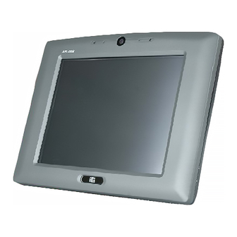
AFL-08B-N270 provides access to external interface connectors. 1.3.1 Front Panel The front side of the AFL-08B-N270 is a TFT LCD screen surrounded by an ABS/PC plastic frame. The top of the front panel has a digital camera and microphone. A power LED is located on the bottom of the front panel with an integrated IEI logo. -
Page 16: Rear Panel
AFL-08B-N270 User Manual Figure 1-2: AFL-08B-N270 Front View 1.3.2 Rear Panel The rear panel provides access to the internal components of the AFL-08B-N270 and CF card slot. Refer to Figure 1-3 for back cover retention screw and VESA mount screw holes. -
Page 17: I/O Interface Panel
AFL-08B-N270 User Manual Figure 1-3: AFL-08B-N270 Rear View 1.3.3 I/O Interface Panel The I/O interface panel located on the bottom of the AFL-08B-N270 has the following I/O interface connectors: 1 x 12 V DC-IN connector 1 x Audio line-out jack... -
Page 18: Internal Overview
AFL-08B-N270 User Manual Figure 1-4: AFL-08B-N270 I/O Interface Connector Panel 1.4 Internal Overview The AFL-08B-N270 has the following components installed internally: 1 x Motherboard 1 x 1.0 GB 533 MHz DDR2 SDRAM SO-DIMM 1 x Wireless LAN module 2 x 1.5W speakers... -
Page 19: System Specifications
AFL-08B-N270 User Manual 1.5 System Specifications The technical specifications for the AFL-08B-N270 systems are listed below. Specifications AFL-08B-N270 8" LCD Size 800 x 600 Max Resolution Brightness (cd/m2) 400:1 Contrast Ratio 262K LCD Color 0.0675(H) x 0.2025(V) Pixel Pitch (mm) 130º/120º... -
Page 20: Dimensions
Input: 100 V AC ~ 240 V AC; 50 Hz ~ 60 Hz Power Adapter Output: 12 V DC 12 V DC Power Requirement 25 W Power Consumption Table 1-1: AFL-08B-N270 Specifications 1.6 Dimensions The AFL-408A/B-N270 dimensions are listed below and shown in the following figure. 234 mm Width: Page 20... -
Page 21: Figure 1-6: Afl-08B-N270 Dimensions (Mm)
AFL-08B-N270 User Manual 177 mm Height: 43 mm Depth: Figure 1-6: AFL-08B-N270 Dimensions (mm) Page 21... -
Page 22: Installation
AFL-08B-N270 User Manual Chapter Installation Page 22... - Page 23 AFL-08B-N270 User Manual WARNING: When installing the AFL-08B-N270, make sure to: Turn the power off: Chance of electrocution. Turn off the monitor and unplug it from the power supply. Only let certified engineers change the hardware settings: Incorrect settings can cause irreparable damage to the product.
-
Page 24: Unpack The Panel Pc
Lift the monitor out of the boxes. Step 5: Remove the peripheral parts box from the main box. Step 6: 2.1.1 Packing List The AFL-08B-N270 panel PC is shipped with the following components: Quantity Item Image AFL-08B-N270 panel PC Power adapter... - Page 25 AFL-08B-N270 User Manual Power cord (P/N: 32702-000400-100-RS) Power transfer cord (P/N: 32702-000300-100-RS) Screw kit (M4*6) (P/N: 44403-040061-RS) Touch pen (P/N: 43125-0002C0-00-RS) User manual CD and driver CD Optional WIN CE 6.0 ALFCF-W10-N270-CE060 WIN XPE ALFCF-W10-N270-XPE Linux ALFCF-W10-N270-LNX-R10 Panel mounting kit...
- Page 26 AFL-08B-N270 User Manual Rack mounting kit (P/N: AFLRK-08) VSTAND: (P/N: VSTAND-A10) Stand (P/N:STAND-A08) Stand (P/N:STAND-100-RS) Stand (P/N: STAND-150-RS) (P/N: ARM-11-RS) (P/N: ARM-31-RS) Page 26...
-
Page 27: Removing The Rear Panel
2.2 Removing the Rear Panel To access the AFL-08B-N270 internally the rear panel must be removed. To remove the rear panel, please follow the steps below. Remove the retention screws (Figure 2-1). -
Page 28: Cf Card Installation
Maximum torque for cover screws is 5 kg-cm (0.36 lb-ft/0.49 Nm). 2.3 CF Card Installation The AFL-08B-N270 has one CF Type II slot inside the rear panel cover. The slot can be accessed after removing the back cover. To install the CF card, follow the instructions below. -
Page 29: Figure 2-2: Cf Card Slot Location
AFL-08B-N270 User Manual Locate the CF slot cover. Remove the retention screw and CF slot cover (Figure Step 1: 2-2). Figure 2-2: CF card slot location Insert a CF card into the slot (Figure 2-3). Step 2: Figure 2-3: CF Card Location Replace the CF card slot cover. -
Page 30: At/Atx Mode Selection
AFL-08B-N270 User Manual 2.4 AT/ATX Mode Selection AT and ATX power modes can both be used on the AFL-08B-N270. The selection is made through an AT/ATX switch on the top edge of the inner aluminum cover (Figure 2-4). To select AT mode or ATX mode, follow the steps below. -
Page 31: Atx Power Mode
AFL-08B-N270 User Manual 2.4.2 ATX Power Mode With the ATX mode selected, the AFL-08B-N270 panel PC goes in a standby mode when it is turned off. The panel PC can be easily turned on via network or a power switch in standby mode. -
Page 32: Access The Jumpers
Do not change the settings on the jumpers in described here. Doing so may disable or damage the system. The following jumpers are preconfigured for the AFL-08B-N270. Users should not change these jumpers ( T able 2-2). The jumper settings of the preconfigured jumpers are listed in Chapter 5 for reference. -
Page 33: Clear Cmos Jumper
Jumper Location: F igure 2-5 If the AFL-08B-N270 fails to boot due to improper BIOS settings, the clear CMOS jumper clears the CMOS data and resets the system BIOS information. To do this, use the jumper cap to close the pins for a few seconds then remove the jumper clip. -
Page 34: Com Port Pin 9 Select
AFL-08B-N270 User Manual Figure 2-5: Clear CMOS Jumper 2.5.4 COM Port Pin 9 Select JP8 and JP10 Jumper Label: Jumper Settings: T able 2-4 Jumper Location: F igure 2-6 Two jumpers (JP8 and JP10) configure pin 9 on COM1 and COM3 DB-9 connectors. Pin 9 on the COM1 and the COM3 DB-9 connectors can be set as the ring (RI) signal, +5 V or +12 V. -
Page 35: Com3 Rx Function Select Jumper
AFL-08B-N270 User Manual Figure 2-6: COM1 and COM3 Pin 9 Setting Jumper Locations 2.5.4.1 COM3 RS-422 and RS-485 Pinouts The pinouts for RS-422 and RS-485 operation of external serial port COM 3 are detailed below. COM 3 RS-422 Description Pin 1... -
Page 36: Com3 Tx Function Select Jumper
AFL-08B-N270 User Manual The COM3 RX Function Select jumper sets the communication protocol used by the RX serial communications port COM3 as RS-232, RS-422 or RS-485. The COM3 RX Function Select jumper settings are shown in T able 2-8. COM3 RX Function Select... -
Page 37: Com3 Rs-232/422/485 Serial Port Select Jumper
AFL-08B-N270 User Manual The COM3 TX Function Select jumper configures the TX pin on COM3 serial port connector as RS-422 as an RS-485. The COM3 TX Function Select jumper selection options are shown in T able 2-9. COM3 TX Function Select Description Short 1 –... -
Page 38: Compactflash® Setup
AFL-08B-N270 User Manual RS-232/485 Select Description Short 1-2 RS-232 Default Short 4-5 RS-232 Default Short 7-8 RS-232 Default Short 10-11 RS-232 Default Short 2-3 RS-422/485 Short 5-6 RS-422/485 Short 8-9 RS-422/485 Short 11-12 RS-422/485 Table 2-10: COM3 RS-232/422/485 Serial Port Select Jumper Settings The COM3 RS-232/422/485 Serial Port Select jumper location is shown in F igure 2-9. -
Page 39: Mounting The System
PC does not fall down and get damaged. The four methods of mounting the AFL-08B-N270 are listed below. Wall mounting Panel mounting... -
Page 40: Wall Mounting
AFL-08B-N270 User Manual 2.6.1 Wall Mounting To mount the panel PC onto the wall, please follow the steps below. Select the location on the wall for the wall-mounting bracket. Step 1: Carefully mark the locations of the four screw holes in the bracket on the wall. -
Page 41: Figure 2-12: Chassis Support Screws
AFL-08B-N270 User Manual Ensure that all four of the mounting screws fit snuggly into their respective slotted holes. NOTE: In the diagram below the bracket is already installed on the wall. Figure 2-12: Chassis Support Screws Secure the panel PC by fastening the retention screw of the wall-mounting Step 9: bracket. -
Page 42: Panel Mounting
AFL-08B-N270 User Manual Figure 2-13: Secure the Panel PC 2.6.2 Panel Mounting To mount the AFL-08B-N270 panel PC into a panel, please follow the steps below. Select the position on the panel to mount the panel PC. Step 1: Cut out a section from the panel that corresponds to the rear panel dimensions Step 2: of the panel PC. -
Page 43: Figure 2-14: Afl-08B-N270 Cutout Dimensions (Units In Mm)
AFL-08B-N270 User Manual Figure 2-14: AFL-08B-N270 Cutout Dimensions (units in mm) Slide the panel PC through the hole until the aluminum frame is flush against the Step 3: panel. Insert the panel mounting clamps into the pre-formed holes along the edges of Step 4: the chassis, behind the aluminum frame. -
Page 44: Cabinet And Rack Installation
Figure 2-15: Tighten the Panel Mounting Clamp Screws 2.6.3 Cabinet and Rack Installation The AFL-08B-N270 panel PC can be installed into a cabinet or rack. The installation procedures are similar to the panel mounting installation. To do this, please follow the... -
Page 45: Figure 2-16: The Rack/Cabinet Bracket
AFL-08B-N270 User Manual Figure 2-16: The Rack/Cabinet Bracket Insert the rack mounting clamps into the pre-formed holes along the edges of Step 2: the panel PC, behind the ABS/PC plastic frame. Tighten the screws that pass through the rack mounting clamps until the plastic... -
Page 46: Arm Mounting
(Figure 2-18). 2.6.4 Arm Mounting The AFL-08B-N270 is VESA (Video Electronics Standards Association) compliant and can be mounted on an arm with a 75mm interface pad. To mount the panel PC on an arm, please follow the steps below. -
Page 47: Bottom Panel Connectors
PC. Step 0: 2.7 Bottom Panel Connectors All I/O interface connections of the AFL-08B-N270 are found on the bottom panel. 2.7.1 LAN Connection There are two external RJ-45 LAN connectors. The RJ-45 connector enables connection to an external network. -
Page 48: Serial Device Connection And Rs-422/485 Pinouts
Series. Align the connector. Align the RJ-45 connector on the LAN cable with one of Step 2: the RJ-45 connectors on the bottom panel of the AFL-08B-N270. See Figure 2-20. Figure 2-20: LAN Connection Insert the LAN cable RJ-45 connector. Once aligned, gently insert the LAN Step 3: cable RJ-45 connector into the onboard RJ-45 connector. -
Page 49: Figure 2-21: Serial Device Connector
AFL-08B-N270 User Manual Insert the serial connector. Insert the DB-9 connector of a serial device into Step 2: the DB-9 connector on the external peripheral interface. See Figure 2-21. Figure 2-21: Serial Device Connector Secure the connector. Secure the serial device connector to the external Step 3: interface by tightening the two retention screws on either side of the connector. -
Page 50: Usb Device Connection
AFL-08B-N270 User Manual Table 2-13: RS-485 Pinouts 2.7.3 USB Device Connection There are two external USB 2.0 connectors. To connect a USB 2.0 or USB 1.1 device, please follow the instructions below. Located the USB connectors. The locations of the USB connectors are shown Step 1: in Chapter 2. -
Page 51: Driver Installation
AFL-08B-N270 User Manual Connect the power adapter to the panel PC. Step 1: Connect the power cable to the included power adapter. Step 2: Connect the power cable to the power outlet. Step 3: S t e p 0 : 2.9 Driver Installation... -
Page 52: System Maintenance
AFL-08B-N270 User Manual Chapter System Maintenance Page 52... -
Page 53: System Maintenance Introduction
Some internal components are easily damaged or destroyed by electrostatic discharge. Take antistatic precautions to prevent electrostatic discharge. If the components of the AFL-08B-N270 fail they must be replaced. Components that can be replaced include (see Figure 3-1): CF Module... -
Page 54: Motherboard Replacement
The motherboard is accessible after opening the rear cover. 3.3 Cover Removal To access the AFL-08B-N270 internally the back panel must be removed. To remove the back panel, please follow the steps below. Follow all anti-static procedures. See Section A.1.2. -
Page 55: Figure 3-2: Back Cover Retention Screws
AFL-08B-N270 User Manual Figure 3-2: Back Cover Retention Screws Lift the cover and pull down the cover a bit to make it possible to fully remove it. Step 4: More strength is required to separate the cover from the chassis. -
Page 56: Memory Module Replacement
Remove the aluminum back cover. See Section 3.3 above. Step 1: Locate the DDR2 SO-DIMM on the motherboard (Figure 3-4). Step 2: Figure 3-4:AFL-08B-N270 SO-DIMM Socket Location Remove the SO-DIMM by pulling both the spring retainer clips outward from the Step 3: socket. -
Page 57: Cf Card Replacement
AFL-08B-N270 User Manual Figure 3-5: DDR2 SO-DIMM Module Installation 3.5 CF Card Replacement The AFL-08B-N270 has one CF Type II slot. Follow the instructions below to replace the CF card. Follow all anti-static procedures. See Section A.1.2. Step 1: Turn off the power. See Section 3.1. - Page 58 AFL-08B-N270 User Manual When maintenance procedures are complete, please make sure all the covers are replaced, including the following: Aluminum cover CF card slot cover Plastic rear cover Page 58...
-
Page 59: Bios Options
AFL-08B-N270 User Manual Chapter BIOS Options Page 59... -
Page 60: Introduction
AFL-08B-N270 User Manual 4.1 Introduction A licensed copy of AMI BIOS is preprogrammed into the ROM BIOS. The BIOS setup program allows users to modify the basic system configuration. This chapter describes how to access the BIOS setup program and the configuration options that may be changed. -
Page 61: Getting Help
AFL-08B-N270 User Manual F1 key General help, only for Status Page Setup Menu and Option Page Setup Menu F2 /F3 key Change color from total 16 colors. F2 to select color forward. F10 key Save all the CMOS changes, only for Main Menu Table 4-1: BIOS Navigation Keys 4.1.3 Getting Help... -
Page 62: Main
AFL-08B-N270 User Manual 4.2 Main The Main menu gives an overview of the basic system information. BIOS SETUP UTILITY Main Advanced PCIPNP Boot Security Chipset Exit System Overview ⎯⎯⎯⎯⎯⎯⎯⎯⎯⎯⎯⎯⎯⎯⎯⎯⎯⎯⎯⎯⎯⎯⎯⎯⎯⎯⎯⎯⎯⎯⎯ AMIBIOS Version :08.00.15 Build Date :10/22/09 :H731MR11 Processor Intel® Atom CPU N270 @ 1.60GHz... -
Page 63: Advanced
AFL-08B-N270 User Manual The System Overview field also has two user configurable fields: System Time [xx:xx:xx] Use the System Time option to set the system time. Manually enter the hours, minutes and seconds. System Date [xx/xx/xx] Use the System Date option to set the system date. Manually enter the day, month and year. -
Page 64: Cpu Configuration
AFL-08B-N270 User Manual BIOS SETUP UTILITY Main Advanced PCIPNP Boot Security Chipset Exit Advanced Settings ⎯⎯⎯⎯⎯⎯⎯⎯⎯⎯⎯⎯⎯⎯⎯⎯⎯⎯⎯⎯⎯⎯⎯⎯⎯⎯⎯⎯⎯⎯⎯ WARNING: Setting wrong values in below sections may cause system to malfunction > CPU Configuration > IDE Configuration Select Screen > SuperIO Configuration ↑ ↓... -
Page 65: Ide Configuration
AFL-08B-N270 User Manual Frequency: Lists the CPU processing speed FSB Speed: Lists the FSB speed Cache L1: Lists the CPU L1 cache size Cache L2: Lists the CPU L2 cache size Ratio Actual Value: the clock multiplier 4.3.2 IDE Configuration Use the IDE Configuration menu to change and/or set the configuration of the IDE devices installed in the system. -
Page 66: Legacy Ide Channels [Sata Pri, Pata Sec]
AFL-08B-N270 User Manual Configures the on-board ATA/IDE controller to be in Enhanced Enhanced mode. In this mode, IDE channels and SATA channels are separated. This mode supports up to 6 storage devices. Some legacy OS do not support this mode. -
Page 67: Bios Menu 5: Ide Master And Ide Slave Configuration
AFL-08B-N270 User Manual BIOS SETUP UTILITY Main Advanced PCIPNP Boot Security Chipset Exit Primary IDE Master ⎯⎯⎯⎯⎯⎯⎯⎯⎯⎯⎯⎯⎯⎯⎯⎯⎯⎯⎯⎯⎯⎯⎯⎯⎯⎯⎯⎯⎯⎯⎯ Device :Not Detected Type [Auto] LBA/Large Mode [Auto] Block (Multi-Sector Transfer) [Auto] Select Screen PIO Mode [Auto] ↑ ↓ Select Item DMA Mode... -
Page 68: Type [Auto]
AFL-08B-N270 User Manual Type [Auto] Use the Type BIOS option select the type of device the AMIBIOS attempts to boot from after the Power-On Self-Test (POST) is complete. BIOS is prevented from searching for an IDE disk Not Installed drive on the specified channel. -
Page 69: Pio Mode [Auto]
AFL-08B-N270 User Manual BIOS is prevented from using Multi-Sector Transfer on the Disabled specified channel. The data to and from the device occurs one sector at a time. BIOS auto detects Multi-Sector Transfer support on the Auto EFAULT drive on the specified channel. If supported the data transfer to and from the device occurs multiple sectors at a time. -
Page 70: Super Io Configuration
AFL-08B-N270 User Manual S.M.A.R.T [Auto] Use the S.M.A.R.T option to auto-detect, disable or enable Self-Monitoring Analysis and Reporting Technology (SMART) on the drive on the specified channel. S.M.A.R.T predicts impending drive failures. The S.M.A.R.T BIOS option enables or disables this function. -
Page 71: Serial Port 1 Address [3F8/Irq4]
AFL-08B-N270 User Manual Serial Port 1 Address [3F8/IRQ4] Sets the port address and IRQ of serial port 1. Disabled 3F8/IRQ4 EFAULT 2F8/IRQ3 3E8/IRQ4 2E8/IRQ3 Serial Port 3 Address [3E8] Sets the port address of serial port 3. Disabled EFAULT Serial Port 3 IRQ [IRQ4] Sets the interrupt address of serial port 3. -
Page 72: Hardware Health Configuration
AFL-08B-N270 User Manual 4.3.4 Hardware Health Configuration The Hardware Health Configuration menu shows the operating temperature, fan speeds and system voltages. BIOS SETUP UTILITY Main Advanced PCIPNP Boot Security Chipset Exit Hardware Health Event Monitoring ⎯⎯⎯⎯⎯⎯⎯⎯⎯⎯⎯⎯⎯⎯⎯⎯⎯⎯⎯⎯⎯⎯⎯⎯⎯⎯⎯⎯⎯⎯⎯ CPU Temperature :53ºC/127ºF System Temperature :42ºC/107F... -
Page 73: Bios Menu 9: General Acpi Configuration
AFL-08B-N270 User Manual 4.3.5.1 ACPI Configuration Use the ACPI Configuration menu ( B IOS Menu 9) to select the ACPI state when the system is suspended. BIOS SETUP UTILITY Main Advanced PCIPNP Boot Security Chipset Exit ACPI Settings ⎯⎯⎯⎯⎯⎯⎯⎯⎯⎯⎯⎯⎯⎯⎯⎯⎯⎯⎯⎯⎯⎯⎯⎯⎯⎯⎯⎯⎯⎯⎯ Suspend mode... -
Page 74: Bios Menu 10: Apm Configuration
AFL-08B-N270 User Manual BIOS SETUP UTILITY Main Advanced PCIPNP Boot Security Chipset Exit APM Configuration ⎯⎯⎯⎯⎯⎯⎯⎯⎯⎯⎯⎯⎯⎯⎯⎯⎯⎯⎯⎯⎯⎯⎯⎯⎯⎯⎯⎯⎯⎯⎯ Restore on AC Power Loss [Last State] Power Button Mode [On/Off] Advanced Resume Event Controls Resume On Ring [Disabled] Select Screen Resume on PCI-Express WAKE# [Enabled] ↑... -
Page 75: Remote Access Configuration
AFL-08B-N270 User Manual Resume on Ring [Disabled] Use the Resume on Ring BIOS option to enable activity on the RI (ring in) modem line to rouse the system from a suspend or standby state. That is, the system will be roused by an incoming call on a modem. -
Page 76: Bios Menu 11: Remote Access Configuration
AFL-08B-N270 User Manual BIOS SETUP UTILITY Main Advanced PCIPNP Boot Security Chipset Exit Configure Remote Access type and parameters ⎯⎯⎯⎯⎯⎯⎯⎯⎯⎯⎯⎯⎯⎯⎯⎯⎯⎯⎯⎯⎯⎯⎯⎯⎯⎯⎯⎯⎯⎯⎯ Remote Access [Disabled] Select Screen ↑ ↓ Select Item Enter Go to SubScreen General Help Save and Exit Exit v02.61 ©Copyright 1985-2006, American Megatrends, Inc. -
Page 77: Base Address, Irq [3F8H,4]
AFL-08B-N270 User Manual NOTE: Make sure the selected COM port is enabled through the Super I/O configuration menu. Base Address, IRQ [3F8h,4] The Base Address, IRQ option cannot be configured and only shows the interrupt address of the serial port listed above. -
Page 78: Usb Configuration
AFL-08B-N270 User Manual Terminal Type [ANSI] Use the Terminal Type BIOS option to specify the remote terminal type. The target terminal type is ANSI ANSI EFAULT The target terminal type is VT100 VT100 The target terminal type is VT-UTF8 VT-UTF8 4.3.7 USB Configuration... -
Page 79: Pci/Pnp
AFL-08B-N270 User Manual USB 2.0 controller enabled Enabled EFAULT USB 2.0 controller disabled Disabled Legacy USB Support [Enabled] Use the Legacy USB Support BIOS option to enable USB mouse and USB keyboard support. Normally if this option is not enabled, any attached USB mouse or USB keyboard does not become available until a USB compatible operating system is fully booted with all USB drivers loaded. -
Page 80: Bios Menu 13: Pci/Pnp Configuration
AFL-08B-N270 User Manual BIOS SETUP UTILITY Main Advanced PCIPNP Boot Security Chipset Exit Advanced PCI/PnP Settings ⎯⎯⎯⎯⎯⎯⎯⎯⎯⎯⎯⎯⎯⎯⎯⎯⎯⎯⎯⎯⎯⎯⎯⎯⎯⎯⎯⎯⎯⎯⎯ WARNING: Setting wrong values in below sections may cause system to malfunction IRQ3 [Reserved] IRQ4 [Reserved] IRQ5 [Available] IRQ7 [Available] IRQ9 [Available] IRQ10... -
Page 81: Dma Channel# [Available]
AFL-08B-N270 User Manual IRQ9 IRQ10 IRQ 11 IRQ 14 IRQ 15 DMA Channel# [Available] Use the DMA Channel# option to assign a specific DMA channel to a particular PCI/PnP device. The specified DMA is available to be used by Available... -
Page 82: Boot
AFL-08B-N270 User Manual 4.5 Boot Use the Boot menu to configure system boot options. BIOS SETUP UTILITY Main Advanced PCIPNP Boot Security Chipset Exit Boot Settings ⎯⎯⎯⎯⎯⎯⎯⎯⎯⎯⎯⎯⎯⎯⎯⎯⎯⎯⎯⎯⎯⎯⎯⎯⎯⎯⎯⎯⎯⎯⎯ > Boot Settings Configuration Select Screen ↑ ↓ Select Item Enter Go to SubScreen... -
Page 83: Quick Boot [Enabled]
AFL-08B-N270 User Manual Quick Boot [Enabled] Use the Quick Boot BIOS option to make the computer speed up the boot process. No POST procedures are skipped Disabled Some POST procedures are skipped to decrease Enabled EFAULT the system boot time Quiet Boot [Enabled] Use the Quiet Boot BIOS option to select the screen display when the system boots. -
Page 84: Boot From Lan Support [Disabled]
AFL-08B-N270 User Manual Allows the Number Lock on the keyboard to be enabled EFAULT automatically when the computer system boots up. This allows the immediate use of the 10-key numeric keypad located on the right side of the keyboard. To confirm this, the Number Lock LED light on the keyboard is lit. -
Page 85: Security
AFL-08B-N270 User Manual 4.6 Security Use the Security menu to set system and user passwords. BIOS SETUP UTILITY Main Advanced PCIPNP Boot Security Chipset Exit Security Settings ⎯⎯⎯⎯⎯⎯⎯⎯⎯⎯⎯⎯⎯⎯⎯⎯⎯⎯⎯⎯⎯⎯⎯⎯⎯⎯⎯⎯⎯⎯⎯ Supervisor Password :Not Installed User Password :Not Installed Change Supervisor Password Change User Password Select Screen ↑... -
Page 86: Chipset
AFL-08B-N270 User Manual 4.7 Chipset Use the Chipset menu to access the Northbridge and Southbridge configuration menus WARNING! Setting the wrong values for the Chipset BIOS selections in the Chipset BIOS menu may cause the system to malfunction. BIOS SETUP UTILITY... -
Page 87: North Bridge Configuration
AFL-08B-N270 User Manual 4.7.1 North Bridge Configuration Use the North Bridge Chipset Configuration menu ( B IOS Menu 18) to configure the Northbridge chipset. BIOS SETUP UTILITY Main Advanced PCIPNP Boot Security Chipset Exit North Bridge Chipset Configuration ⎯⎯⎯⎯⎯⎯⎯⎯⎯⎯⎯⎯⎯⎯⎯⎯⎯⎯⎯⎯⎯⎯⎯⎯⎯⎯⎯⎯⎯⎯⎯ Memory Hole... -
Page 88: Dvmt Mode Select [Dvmt Mode]
AFL-08B-N270 User Manual 1 MB of memory used by internal graphics device Enable, 1 MB 8 MB of memory used by internal graphics device Enable, 8 MB EFAULT DVMT Mode Select [DVMT Mode] Use the DVMT Mode Select option to select the Intel Dynamic Video Memory Technology (DVMT) operating mode. -
Page 89: South Bridge Configuration
AFL-08B-N270 User Manual 800x600 18b 1024x768 18b 1280x1024 36b 1400x1050 36b 1440x900 36b 1600x1200 36b 1024x600 18b by H/W LFP Current Jumper Setting [1024x600 18b] Displays the resolution setting of the LFP port by the on-board jumper. 4.7.2 South Bridge Configuration The South Bridge Configuration menu the Southbridge chipset to be configured. -
Page 90: Exit
AFL-08B-N270 User Manual 4.8 Exit Use the Exit menu to load default BIOS values, optimal failsafe values and to save configuration changes. BIOS SETUP UTILITY Main Advanced PCIPNP Boot Security Chipset Exit Exit Options ⎯⎯⎯⎯⎯⎯⎯⎯⎯⎯⎯⎯⎯⎯⎯⎯⎯⎯⎯⎯⎯⎯⎯⎯⎯⎯⎯⎯⎯⎯⎯ Save Changes and Exit Discard Changes and Exit... -
Page 91: Load Failsafe Defaults
AFL-08B-N270 User Manual Load Failsafe Defaults Use the Load Failsafe Defaults option to load failsafe default values for each of the parameters on the Setup menus. F8 key can be used for this operation. Page 91... -
Page 92: Interface Connectors
AFL-08B-N270 User Manual Chapter Interface Connectors Page 92... -
Page 93: Peripheral Interface Connectors
AFL-08B-N270 User Manual 5.1 Peripheral Interface Connectors The AFL-08B-N270 panel PC motherboard comes with a number of peripheral interface connectors and configuration jumpers. The connector locations are shown in Figure 6-1. The Pin 1 locations of the on-board connectors are also indicated in the diagram below. -
Page 94: Internal Peripheral Connectors
Internal peripheral connectors are found on the motherboard and are only accessible when the motherboard is outside of the chassis. The table below shows a list of the peripheral interface connectors on the AFL-08B-N270 motherboard. Pinouts of these connectors can be found in the following sections. -
Page 95: Audio Line-Out Connector (Cn8)
AFL-08B-N270 User Manual Connector Type Label CRT connector 10-pin header DIO connector 10-pin header DIO1 HDD power connector 4-pin wafer LED indicator and button connector 10-pin header LVDS backlight connector 6-pin wafer INVERTER1 MCU connector 8-pin header 10-pin header PCIe Mini card slot... -
Page 96: Audio Speaker-Out Connector (Cn3)
AFL-08B-N270 User Manual 5.2.2 Audio Speaker-out Connector (CN3) PIN NO. DESCRIPTION AMP_L+ AMP_L- AMP_R- AMP_R+ Table 5-3: Audio Speaker-out Connector (CN3) Pinouts 5.2.3 Audio MIC-in Connector (MIC1) PIN NO. DESCRIPTION MIC_IN_L AGND_AMP MIC_JD MIC1_IN_R Table 5-4: Audio MIC-in Connector (MIC1) Pinouts 5.2.4 Audio DMIC-in Connector (DMIC1) -
Page 97: Battery Connector (Bt1)
AFL-08B-N270 User Manual 5.2.5 Battery Connector (BT1) PIN NO. DESCRIPTION Battery +3.3V Table 5-6: Battery Connector (BT1) Pinouts 5.2.6 CompactFlash® Type II Slot (CF1) PIN NO. DESCRIPTION PIN NO. DESCRIPTION GROUND1 DATA 3 DATA 11 DATA 4 DATA 12 DATA 5... -
Page 98: Crt Connector (Cn4)
AFL-08B-N270 User Manual PIN NO. DESCRIPTION PIN NO. DESCRIPTION IOCS16 DATA 10 GROUND2 Table 5-7: CompactFlash® Slot (CF1) Pinouts 5.2.7 CRT Connector (CN4) PIN NO. DESCRIPTION PIN NO. DESCRIPTION DACR_RED SPD2 DACG_GREEN SPCLK2 DACB_BLUE V_GND H_SYNC V_GND V_SYNC V_GND Table 5-8: CRT Connector (CN4) Pinouts 5.2.8 DIO Connector (DIO1) -
Page 99: Led Indicator And Button Connector (Jp2)
AFL-08B-N270 User Manual 5.2.10 LED Indicator and Button Connector (JP2) PIN NO. DESCRIPTION PIN NO. DESCRIPTION PW_LED +5V HD_LED SUS PW LED +5V RST_SW PW_BN Table 5-11: LED Indicator and Button Connector (JP2) Pinouts 5.2.11 LVDS Backlight Connector (INVERTER1) PIN NO. -
Page 100: Mcu Connector (Ts2)
AFL-08B-N270 User Manual 5.2.13 MCU Connector (TS2) PIN NO. DESCRIPTION AUTO_DIMMING LOCK_BUTTON VOL+ VOL- BRIGHT+ BRIGHT- LCD_ON_OFF Table 5-14: MCU Connector (TS2) Pinouts 5.2.14 PCIe Mini Slot (CN2) PIN NO. DESCRIPTION PIN NO. DESCRIPTION PCIE_WAKE# VCC3 RESERVED RESERVED 1.5 V... -
Page 101: Rfid Connector (Jp8)
AFL-08B-N270 User Manual PIN NO. DESCRIPTION PIN NO. DESCRIPTION RESERVED USBD+ RESERVED RESERVED LED_WWAN# RESERVED LED_WLAN# RESERVED LED_WPAN# RESERVED 1.5 V RESERVED RESERVED VCC3 Table 5-15: PCIe Mini Card Slot (CN2) Pinouts 5.2.15 RFID Connector (JP8) PIN NO. DESCRIPTION PIN NO. -
Page 102: Touch Panel Connector (Ts1)
AFL-08B-N270 User Manual 5.2.17 Touch Panel Connector (TS1) PIN NO. 8-Wire 4-Wire 5-Wire Right Sense Left Sense Bottom Sense Top Sense Sense (S) Right Excite Right LR (X) Left Excite Left LL (L) Bottom Excite Bottom UR (Y) Top Excite... -
Page 103: Jusb Connector (Jusb1)
AFL-08B-N270 User Manual TFT_B2 TFT_B1 DOTCLK TFT_B0 Table 5-19: TTL Panel Connector (CN7) Pinouts 5.2.19 JUSB Connector (JUSB1) PIN NO. DESCRIPTION +5Vsus D6F- D6F+ Table 5-20: JUSB Connector (JUSB1) Pinouts 5.2.20 USB Connector (USB1) PIN NO. DESCRIPTION PIN NO. DESCRIPTION... -
Page 104: Usb Connector (Usb4)
USB Power (selected by JP15) D3F- D3F+ Table 5-23: USB Connector (USB4) Pinouts 5.3 External Interface Panel Connectors The table below lists the rear panel connectors on the AFL-08B-N270 motherboard. Pinouts of these connectors can be found in the following sections. Connector Type Label... -
Page 105: Power Connector (Cn5)
AFL-08B-N270 User Manual +3.3Vsus ACT-1 LAN1_LINK1000 LAN1_LINK100 +3.3Vsus +3.3Vsus Table 5-25: Ethernet Connector (LAN1, LAN2) Pinouts 5.3.2 Power Connector (CN5) PIN NO. DESCRIPTION VCC12_IN Table 5-26: Power Connector (CN5) Pinouts 5.3.3 RS-232 Serial Ports (COM1) PIN NO. DESCRIPTION PIN NO. -
Page 106: Sata Connector (Sata2)
AFL-08B-N270 User Manual PIN NO. RS-232 RS-422 RS-485 NDTR3 NDSRB NRTSB NCTS3 COM_RI3 Table 5-28: COM3 Connector Pinouts 5.3.5 SATA Connector (SATA2) PIN NO. DESCRIPTION STXP_0 STXN_0 SRXN_0 SRXP_0 Table 5-29: SATA Connector (SATA2) Pinouts 5.3.6 USB 2.0 Connectors (USB3) PIN NO. -
Page 107: Preconfigured Jumper Settings
AFL-08B-N270 User Manual 5.4 Preconfigured Jumper Settings The following jumpers are preconfigured for the AFL-08B-N270. Users should not change these jumpers ( T able 5-31). It is only for reference. Jumper Name Label Type Backlight voltage selection J_BL1 3-pin header... -
Page 108: Lvds Panel Voltage Selection Jumper (J_Vlvds1)
AFL-08B-N270 User Manual 5.4.3 LVDS Panel Voltage Selection Jumper (J_VLVDS1) Description Short 1-2 +3.3 V (Default) Short 2-3 +5 V Table 5-34: LVDS Voltage Selection Jumper (J_VLVDS1) Settings 5.4.4 MCU LCD Type Selection Jumper (JP14) Description Short 1-3 LCD Panel (Default) -
Page 109: Touchscreen Selection Jumper (J1)
AFL-08B-N270 User Manual 5.4.7 Touchscreen Selection Jumper (J1) Description Short 1-2 5-wire (Default) Short 3-4 4-wire Table 5-38: Touchscreen Selection Jumper (J1) Settings 5.4.8 USB2 and USB4 Power Selection Jumper (JP15) Description Short 1-3 USB4 +3.3V Short 3-5 USB4 +5V (Default) Short 2-4 USB2 +3.3V... -
Page 110: Safety Precautions
AFL-08B-N270 User Manual Appendix Safety Precautions Page 110... - Page 111 Do not apply voltage levels that exceed the specified voltage range. Doing so may cause fire and/or an electrical shock. Electric shocks can occur if the AFL-08B-N270 chassis is opened when the AFL-08B-N270 is running. Do not drop or insert any objects into the ventilation openings of the AFL-08B-N270.
- Page 112 Electrostatic discharge (ESD) can cause serious damage to electronic components, including the AFL-08B-N270. Dry climates are especially susceptible to ESD. It is therefore critical that whenever the AFL-08B-N270 is opened and any of the electrical components are handled, the following anti-static precautions are strictly adhered to.
- Page 113 Please follow the national guidelines for electrical and electronic product disposal. A.2 Maintenance and Cleaning Precautions When maintaining or cleaning the AFL-08B-N270, please follow the guidelines below. A.2.1 Maintenance and Cleaning Prior to cleaning any part or component of the AFL-08B-N270, please read the details below. Page 113...
- Page 114 AFL-08B-N270 User Manual Except for the LCD panel, never spray or squirt liquids directly onto any other components. To clean the LCD panel, gently wipe it with a piece of soft dry cloth or a slightly moistened cloth. The interior does not require cleaning. Keep fluids away from the interior.
- Page 115 AFL-08B-N270 User Manual Appendix BIOS Options Page 115...
- Page 116 AFL-08B-N270 User Manual Below is a list of BIOS configuration options in the BIOS chapter. System Overview .........................62 System Time [xx:xx:xx] .......................63 System Date [xx/xx/xx] ......................63 ATA/IDE Configurations [Compatible]................65 Legacy IDE Channels [SATA Pri, PATA Sec] ..............66 ...
- Page 117 AFL-08B-N270 User Manual USB2.0 Controller Mode [HiSpeed]..................79 IRQ#............................80 DMA Channel# [Available] ....................81 Reserved Memory Size [Disabled] ..................81 Quick Boot [Enabled] ......................83 Quiet Boot [Enabled] ......................83 AddOn ROM Display Mode [Force BIOS] ................83 ...
- Page 118 AFL-08B-N270 User Manual Appendix ALC892 Digital Microphone Configuration Page 118...
-
Page 119: Figure C-1: Realtek Hd Audio Manager Icon [Task Bar]
AFL-08B-N270 User Manual C.1 ALC892 Digital Microphone Configuration To enable the ALC892 digital microphone function, follow the steps below. Make sure the Realtek ALC892 high definition audio driver has been installed on Step 1: the system. If the audio driver has not been installed on the system, please refer to Section 2.9. -
Page 120: Figure C-3: Mixer Screen
AFL-08B-N270 User Manual Click the Mixer ToolBox icon in the Record section (Figure C-3) Step 5: Figure C-3: Mixer Screen The following screen appears (Figure C-4). Check the Enable recording Step 6: multi-streaming box, and then click OK. Figure C-4: Mixer ToolBox Screen... -
Page 121: Figure C-5: Enabling The Digital Microphone Function
AFL-08B-N270 User Manual From the dropdown list box in the Record section, select Mic in at front panel Step 7: (White) (Figure C-5). The digital microphone function is now enabled. Figure C-5: Enabling the Digital Microphone Function Page 121... - Page 122 AFL-08B-N270 User Manual Appendix Terminology Page 122...
- Page 123 AFL-08B-N270 User Manual Audio Codec 97 (AC’97) refers to a codec standard developed by Intel® AC ’97 in 1997. Advanced Configuration and Power Interface (ACPI) is an OS-directed ACPI configuration, power management, and thermal management interface. Advanced Host Controller Interface (AHCI) is a SATA Host controller AHCI register-level interface.
- Page 124 AFL-08B-N270 User Manual Dual Inline Memory Modules are a type of RAM that offer a 64-bit data DIMM bus and have separate electrical contacts on each side of the module. The Enhanced Host Controller Interface (EHCI) specification is a EHCI register-level interface description for USB 2.0 Host Controllers.
- Page 125 AFL-08B-N270 User Manual Random Access Memory (RAM) is volatile memory that loses data when power is lost. RAM has very fast data transfer rates compared to other storage like hard drives. Serial ATA (SATA) is a serial communications bus designed for data SATA transfers between storage devices and the computer chipsets.
-
Page 126: Watchdog Timer
AFL-08B-N270 User Manual Appendix Watchdog Timer Page 126... - Page 127 AFL-08B-N270 User Manual NOTE: The following discussion applies to DOS environment. IEI support is contacted or the IEI website visited for specific drivers for more sophisticated operating systems, e.g., Windows and Linux. The Watchdog Timer is provided to ensure that standalone systems can always recover from catastrophic conditions that cause the CPU to crash.
-
Page 128: Example Program
AFL-08B-N270 User Manual NOTE: When exiting a program it is necessary to disable the Watchdog Timer, otherwise the system resets. Example program: ; INITIAL TIMER PERIOD COUNTER W_LOOP: AX, 6F02H ;setting the time-out value BL, 30 ;time-out value is 48 seconds ;... - Page 129 AFL-08B-N270 User Manual Appendix Hazardous Materials Disclosure Page 129...
- Page 130 AFL-08B-N270 User Manual F.1 Hazardous Materials Disclosure Table for IPB Products Certified as RoHS Compliant Under 2002/95/EC Without Mercury The details provided in this appendix are to ensure that the product is compliant with the Peoples Republic of China (China) RoHS standards. The table below acknowledges the presences of small quantities of certain materials in the product, and is applicable to China RoHS only.
- Page 131 AFL-08B-N270 User Manual Part Name Toxic or Hazardous Substances and Elements Lead Mercury Cadmium Hexavalent Polybrominated Polybrominated (Pb) (Hg) (Cd) Chromium Biphenyls Diphenyl Ethers (CR(VI)) (PBB) (PBDE) Housing Display Printed Circuit Board Metal Fasteners Cable Assembly Fan Assembly Power Supply...
- Page 132 AFL-08B-N270 User Manual 此附件旨在确保本产品符合中国 RoHS 标准。以下表格标示此产品中某有毒物质的含量符 合中国 RoHS 标准规定的限量要求。 本产品上会附有”环境友好使用期限”的标签,此期限是估算这些物质”不会有泄漏或突变”的 年限。本产品可能包含有较短的环境友好使用期限的可替换元件,像是电池或灯管,这些元 件将会单独标示出来。 部件名称 有毒有害物质或元素 铅 汞 镉 六价铬 多溴联苯 多溴二苯醚 (Pb) (Hg) (Cd) (CR(VI)) (PBB) (PBDE) 壳体 显示 印刷电路板 金属螺帽 电缆组装 风扇组装 电力供应组装 电池 O: 表示该有毒有害物质在该部件所有物质材料中的含量均在 SJ/T11363-2006 标准规定的限量要求以下。 X: 表示该有毒有害物质至少在该部件的某一均质材料中的含量超出 SJ/T11363-2006 标准规定的限量要求。...
Need help?
Do you have a question about the AFL-08B-N270 and is the answer not in the manual?
Questions and answers