Chapters
Table of Contents

Related Manuals for IEI Technology AFL2-W15A-N270


Summary of Contents for IEI Technology AFL2-W15A-N270
- Page 1 AFL2-W15A-N270 Panel PC MODEL: AFL2-W15A-N270 Panel PC with Intel® Atom™ N270 CPU, Touchscreen Gigabit Ethernet, USB, Audio, RS-232/422/485, SATA RoHS Compliant, IP 64 Protection User Manual Page i Rev. 2.00 – 29 August 2013...
- Page 2 AFL2-W15A-N270 Panel PC Revision Date Version Changes 29 August 2013 2.00 Updated for R20 version 28 June, 2013 1.01 Updated Section 2.8: Mounting the System 28 March, 2011 1.00 Initial release Page ii...
- Page 3 AFL2-W15A-N270 Panel PC Copyright COPYRIGHT NOTICE The information in this document is subject to change without prior notice in order to improve reliability, design and function and does not represent a commitment on the part of the manufacturer. In no event will the manufacturer be liable for direct, indirect, special, incidental, or consequential damages arising out of the use or inability to use the product or documentation, even if advised of the possibility of such damages.
-
Page 4: Table Of Contents
AFL2-W15A-N270 Panel PC Table of Contents 1 INTRODUCTION......................1 1.1 O ........................2 VERVIEW 1.2 M ....................3 ODEL ARIATIONS 1.3 F ........................3 EATURES 1.4 E ....................4 XTERNAL VERVIEW 1.4.1 Front Panel ......................4 1.4.2 Rear Panel ......................4 1.4.3 Bottom Panel...................... - Page 5 AFL2-W15A-N270 Panel PC 2.8.2 Panel Mounting....................30 2.8.3 Stand Mounting ....................32 2.8.4 Wall Mounting....................33 2.9 B ................. 36 OTTOM ANEL ONNECTORS 2.9.1 LAN Connection....................37 2.9.2 Serial Device Connection ................37 2.9.3 USB Device Connection................... 38 2.9.4 VGA Monitor Connection ................39 2.10 P...
- Page 6 AFL2-W15A-N270 Panel PC 3.5.3 Hard Disk Drives ..................... 71 3.6 S ......................... 71 ECURITY 3.7 A ................. 72 DVANCED HIPSET ETTINGS 3.7.1 North Bridge Configuration................73 3.7.2 South Bridge Configuration................75 3.8 E ......................... 77 4 SYSTEM MAINTENANCE ..................79 4.1 S...
- Page 7 AFL2-W15A-N270 Panel PC B.4.4 Manual......................110 B.5 O .....................111 THER NFORMATION B.5.1 Using AHCI Mode or ALi M5283 / VIA VT6421A Controller......111 B.5.2 System Memory Requirement .................113 C BIOS OPTIONS ......................114 D TERMINOLOGY ......................117 E WATCHDOG TIMER....................121 F HAZARDOUS MATERIALS DISCLOSURE............124 F.1 H...
- Page 8 List of Figures Figure 1-1: AFL2-W15A-N270 ......................2 Figure 1-2: Front Panel ........................4 Figure 1-3: Rear Panel........................5 Figure 1-4: AFL2-W15A-N270 Bottom Panel................6 Figure 1-5: Dimensions........................9 Figure 2-1: HDD Access Panel Retention Screws..............14 Figure 2-2: HDD/CF Card Brackets Retention Screws..............14 Figure 2-3: HDD Bracket Retention Screws................15 Figure 2–4: HDD Installation......................15...
- Page 9 AFL2-W15A-N270 Panel PC Figure 2-26: AFL2-W15A-N270 Bottom Panel................36 Figure 2-27: LAN Connection ......................37 Figure 2-28: Serial Device Connector..................38 Figure 2-29: USB Device Connection ..................38 Figure 2-30: VGA Connector .......................39 Figure 4-1: SO-DIMM Module Installation...................80 Figure B-1: IEI One Key Recovery Tool Menu ................87 Figure B-2: Launching the Recovery Tool .................91...
- Page 10 AFL2-W15A-N270 Panel PC Figure B-30: System Backup Complete Window ..............108 Figure B-31: Restore Backup ....................109 Figure B-32: Restore System Backup Complete Window ............. 109 Figure B-33: Symantec Ghost Window ................... 110 Page x...
- Page 11 Table 1-1: Model Variations ......................3 Table 1-2: System Specifications....................8 Table 2-1: Packing List.........................13 Table 2-2: AFL2-W15A-N270 Jumpers..................20 Table 2-3: CF Card Setup Jumper Settings ................20 Table 2-4: Clear CMOS Jumper Settings..................22 Table 2-5: COM1 Pin 9 Setting Jumper Settings ...............23 Table 2-6: COM3 Pin 9 Setting Jumper Settings ...............24...
- Page 12 AFL2-W15A-N270 Panel PC BIOS Menus BIOS Menu 1: Main ........................44 BIOS Menu 2: Advanced ......................45 BIOS Menu 3: CPU Configuration ....................46 BIOS Menu 4: IDE Configuration....................47 BIOS Menu 5: IDE Master and IDE Slave Configuration ............48 BIOS Menu 6: Super IO Configuration..................52 BIOS Menu 7: Hardware Health Configuration ................54...
-
Page 13: Introduction
AFL2-W15A-N270 Panel PC Chapter Introduction Page 1... -
Page 14: Overview
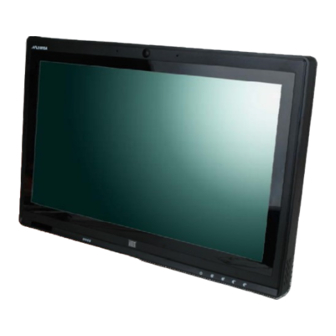
AFL2-W15A-N270 Panel PC 1.1 Overview Figure 1-1: AFL2-W15A-N270 The Afolux panel PCs are all-in-one panel PCs with all the elements of a desktop computer contained in a single, slim package, no bigger than a thick monitor. The Afolux panel PCs can be mounted on a desktop monitor stand and save a huge amount of desktop space by including all the computer components behind the screen. -
Page 15: Model Variations
AFL2-W15A-N270 Panel PC 1.2 Model Variations There are two models of the AFL2-W15A-N270 series. The model variations are listed below. Model Touchscreen 1.6 GHz Intel® Atom Projected capacitive type AFL2-W15A-N270/PC/1G-R20 processor N270 1.6 GHz Intel® Atom Resistive type AFL2-W15A-N270/R/1G-R20 processor N270 Table 1-1: Model Variations 1.3 Features... -
Page 16: External Overview
The rear panel contains a smaller access panel, all the cable connections and the mounting holes. 1.4.1 Front Panel The front side of the AFL2-W15A-N270 is a flat panel LCD screen surrounded by a plastic frame. Figure 1-2: Front Panel 1.4.2 Rear Panel... -
Page 17: Bottom Panel
AFL2-W15A-N270 Panel PC Figure 1-3: Rear Panel 1.4.3 Bottom Panel The bottom panel has the following slots, buttons and switches: 1 x Audio Line-out jack 1 x RJ-45 jack for Gigabit LAN 2 x USB ports 1 x External SATA port... -
Page 18: Internal Overview
AFL2-W15A-N270 Panel PC Figure 1-4: AFL2-W15A-N270 Bottom Panel 1.5 Internal Overview All the components are contained under the rear panel. The internal components include the touch panel module and the motherboard. The motherboard has memory, a wireless module and a SATA hard drive bay. -
Page 19: Specifications
AFL2-W15A-N270 Panel PC 1.6 Specifications The technical specifications for the AFL2-W15A-N270 systems are listed in Table 1-2. SPECIFICATIONS AFL2-W15A-N270/R/1G-R20 AFL2-W15A-N270/PC/1G-R20 LCD Panel 15.6" Resolution 1366 x 768 Brightness Contrast Ratio 500:1 LCD Colors 16.7 million Pixel Pitch 0.252 x 0.252... -
Page 20: Table 1-2: System Specifications
AFL2-W15A-N270 Panel PC SPECIFICATIONS AFL2-W15A-N270/R/1G-R20 AFL2-W15A-N270/PC/1G-R20 1 x Gigabit LAN 1 x Audio line-out 1 x Power input (12 V) 1 x RS-232 1 x RS-232/422/485 2 x USB ports 1 x VGA port 1 x External SATA 1 x Power Button... -
Page 21: Dimensions
AFL2-W15A-N270 Panel PC 1.7 Dimensions Width: 400 mm; Height: 267 mm; Depth: 54 mm. Figure 1-5: Dimensions Page 9... -
Page 22: Installation
AFL2-W15A-N270 Panel PC Chapter Installation Page 10... - Page 23 AFL2-W15A-N270 Panel PC WARNING: When installing the AFL2-W15A-N270, make sure to: Turn the power off: Chance of electrocution. Turn off the monitor and unplug it from the power supply. Only let certified engineers change the hardware settings: Incorrect settings can cause irreparable damage to the product.
-
Page 24: Unpack The Panel Pc
Lift the monitor out of the boxes. Step 5: Remove the peripheral parts box from the main box. Step 6: S t e p 0 : 2.2 Packing List The AFL2-W15A-N270 flat panel PC is shipped with the following components: Quantity Item Image AFL2-W15A-N270 Power adapter... -
Page 25: Hard Drive Installation
If any of these items are missing or damaged, contact the distributor or sales representative immediately. 2.3 Hard Drive Installation This section outlines the installation of the hard drive in the AFL2-W15A-N270. To install the hard drive, please follow the steps below: Unfasten the right plastic side access panel (SATA/CF card/USB dongle access... -
Page 26: Figure 2-1: Hdd Access Panel Retention Screws
AFL2-W15A-N270 Panel PC Figure 2-1: HDD Access Panel Retention Screws Locate the HDD/CF card brackets. Unfasten screws and removed brackets Step 2: (Figure 2-2). Figure 2-2: HDD/CF Card Brackets Retention Screws Attach the HDD brackets to the HDD. To do this, align the two retention screw... -
Page 27: Figure 2-3: Hdd Bracket Retention Screws
AFL2-W15A-N270 Panel PC Figure 2-3: HDD Bracket Retention Screws Insert the SATA connector end of the HDD into the bracket to connect the Step 4: motherboard SATA connector to the hard drive SATA connector. Install the two retention screws (removed in Step 2) to secure the HDD. -
Page 28: Compactflash® Installation
AFL2-W15A-N270 Panel PC 2.4 CompactFlash® Installation The installation for a CompactFlash® card is described in this section. Remove the access panel and brackets as described in the HDD installation Step 1: instructions. Locate the CompactFlash® slot as shown in Figure 2–5. -
Page 29: Usb Dongle Installation
AFL2-W15A-N270 Panel PC 2.5 USB Dongle Installation The installation for an USB dongle is described in this section. Remove the access panel and brackets as described in the HDD installation Step 1: instructions. Locate the USB dongle connector and install the USB dongle as shown below. -
Page 30: Figure 2-8: Plastic Back Cover Retention Screws
To access the internal components, the plastic back cover and the internal aluminum cover of the AFL2-W15A-N270 must be removed. To remove the back cover, unfasten the retention screws and then lift the cover to remove. Figure 2-8: Plastic Back Cover Retention Screws To remove the internal aluminum cover, unfasten the eight retention screws and then lift the cover to remove. -
Page 31: Jumper Settings
The following jumpers can be found on the motherboard installed in the AFL2-W15A-N270. Before the AFL2-W15A-N270 is installed, the jumpers must be set in accordance with the desired configuration. The jumpers on the AFL2-W15A-N270 motherboard are listed in Table 2-2. -
Page 32: Access The Jumpers
12-pin header COM3 TX RS-422/485 select JP11 6-pin header Table 2-2: AFL2-W15A-N270 Jumpers 2.7.1 Access the Jumpers To access the jumpers, please remove the back panel and the internal aluminum chassis. To remove the back panel, please refer to Section 2.6. -
Page 33: Clear Cmos Jumper
See Figure 2-11 Jumper Location: If the AFL2-W15A-N270 fails to boot due to improper BIOS settings, the clear CMOS jumper clears the CMOS data and resets the system BIOS information. To do this, use the jumper cap to close the pins for a few seconds then remove the jumper clip. -
Page 34: Com 1 Port Pin 9 Select
AFL2-W15A-N270 Panel PC Clear CMOS Description Short 1 - 2 Keep CMOS Setup (Default) Short 2 - 3 Clear CMOS Setup Table 2-4: Clear CMOS Jumper Settings The location of the clear CMOS jumper is shown in Figure 2-11 below. -
Page 35: Com 3 Port Pin 9 Select
AFL2-W15A-N270 Panel PC Short 7-9 COM1 RI Pin use +5 V (Default) Table 2-5: COM1 Pin 9 Setting Jumper Settings The COM1 Pin 9 Setting jumper locations are shown in Figure 2-12 below. Figure 2-12: COM1 Pin 9 Setting Jumper Location 2.7.5 COM 3 Port Pin 9 Select... -
Page 36: Com3 Rx Function Select Jumper
AFL2-W15A-N270 Panel PC Short 5-6 COM3 RI Pin use +5 V Table 2-6: COM3 Pin 9 Setting Jumper Settings The COM3 Pin 9 Setting jumper locations are shown in Figure 2-12 below. Figure 2-13: COM3 Pin 9 Setting Jumper Location 2.7.6 COM3 RX Function Select Jumper... -
Page 37: Com3 Rs-232/422/485 Serial Port Select Jumper
AFL2-W15A-N270 Panel PC Short 7-8 RS-485 Table 2-7: COM3 RX Function Select Jumper Settings The COM3 RX Function Select jumper location is shown in Figure 2-14. Figure 2-14: COM3 RX Function Select Jumper Location 2.7.7 COM3 RS-232/422/485 Serial Port Select Jumper... -
Page 38: Com3 Tx Function Select Jumper
AFL2-W15A-N270 Panel PC Table 2-8: COM3 RS-232/422/485 Serial Port Select Jumper Settings The COM3 RS-232/422/485 Serial Port Select jumper location is shown in Figure 2-15. Figure 2-15: COM3 RS-232/422/485 Serial Port Select Jumper Location 2.7.8 COM3 TX Function Select Jumper... -
Page 39: Com3 Rs-422 And Rs-485 Pinouts
AFL2-W15A-N270 Panel PC Short 4 – 6 RS-485 D+ Table 2-9: COM3 TX Function Select Jumper Settings The COM3 TX Function Select jumper location is shown in Figure 2-16 below. Figure 2-16: COM3 TX Function Select Jumper Location 2.7.8.1 COM3 RS-422 and RS-485 Pinouts The pinouts for RS-422 and RS-485 operation of external serial port COM 3 are detailed below. -
Page 40: Mounting The System
2.8.1 Arm Mounting The AFL2-W15A-N270 is VESA (Video Electronics Standards Association) compliant and can be mounted on an arm with a 100 mm interface pad. To mount the AFL2-W15A-N270 on an arm, please follow the steps below. The arm is a separately purchased item. Please correctly mount the arm onto Step 1: the surface it uses as a base. -
Page 41: Figure 2-17: Arm Mount Retention Screw Holes
AFL2-W15A-N270. The AFL2-W15A-N270 arm mount retention screw holes are shown in Figure 2-17. Figure 2-17: Arm Mount Retention Screw Holes Secure the AFL2-W15A-N270 to the interface pad by inserting four retention Step 4: screws through the mounting arm interface pad and into the AFL2-W15A-N270. -
Page 42: Panel Mounting
AFL2-W15A-N270 Panel PC Figure 2-18: Arm Mounting (ARM-11-RS) 2.8.2 Panel Mounting To mount the panel PC into a panel, please follow the steps below. Select the position on the panel to mount the flat panel PC. Step 1: Cut out a section corresponding to the size shown below. The size must be Step 2: smaller then the outer edge. -
Page 43: Figure 2-19: Cutout
Step 6: of the panel mounting brackets (Figure 2-20 ). There are a total of 4 panel mounting clamps for the AFL2-W15A-N270. Tighten the screws that pass through the panel mounting clamps until the plastic Step 7: caps at the front of all the screws are firmly secured to the panel... -
Page 44: Stand Mounting
2.8.3 Stand Mounting To mount the AFL2-W15A-N270 using the stand mounting kit, please follow the steps below. Locate the screw holes on the rear of the AFL2-W15A-N270. This is where the Step 1: bracket will be attached. Align the bracket with the screw holes. -
Page 45: Wall Mounting
AFL2-W15A-N270 Panel PC Figure 2-21: Stand Mounting (Stand-A19) 2.8.4 Wall Mounting To mount the flat panel PC onto the wall, please follow the steps below. Figure 2-22: Wall Mount Select the location on the wall for the wall-mounting bracket. Step 1: Carefully mark the locations of the four brackets screw holes on the wall. -
Page 46: Figure 2-23: Wall-Mounting Bracket
AFL2-W15A-N270 Panel PC Drill four pilot holes at the marked locations on the wall for the bracket retention Step 3: screws. Align the wall-mounting bracket screw holes with the pilot holes. Step 4: Secure the mounting-bracket to the wall by inserting the retention screws into Step 5: the four pilot holes and tightening them (Figure 2-23). -
Page 47: Figure 2-24: Chassis Support Screws
AFL2-W15A-N270 Panel PC Figure 2-24: Chassis Support Screws NOTE: In the diagram below the bracket is already installed on the wall. Secure the panel PC by fastening the retention screw of the wall-mounting Step 9: bracket. (Figure 2-25). Page 35... -
Page 48: Bottom Panel Connectors
AFL2-W15A-N270 Panel PC Figure 2-25: Secure the Panel PC 2.9 Bottom Panel Connectors The bottom panel connectors extend the capabilities of the panel PC but are not essential for operation (except power). Figure 2-26: AFL2-W15A-N270 Bottom Panel Page 36... -
Page 49: Lan Connection
2.9.2 Serial Device Connection The serial device connectors are for connecting serial devices to the AFL2-W15A-N270. Follow the steps below to connect a serial device to the AFL2-W15A-N270 panel PC. Locate the DB-9 connector. The location of the DB-9 connector is shown in Step 1: Figure 2-26. -
Page 50: Usb Device Connection
Step 0: 2.9.3 USB Device Connection To connect USB devices to the AFL2-W15A-N270, please follow the instructions below. Located the USB connectors. The locations of the USB connectors are shown Step 1: in Figure 2-26. -
Page 51: Vga Monitor Connection
2.9.4 VGA Monitor Connection The VGA output can be connected to an external VGA monitor. To connect the VGA monitor to the AFL2-W15A-N270, please follow the instructions below. Locate the female DB-15 connector. The location of the female DB-15 Step 1: connector is shown in Figure 2-26. -
Page 52: Power Connection
Wireless LAN card driver NOTE: There two kinds of touchscreen driver in the driver CD. Please follow the guideline below to install the correct driver for the system: Multi Touch for the AFL2-W15A-N270/PC/1G-R20 Single Touch for the AFL2-W15A-N270/R/1G-R20 Page 40... -
Page 53: Bios Setup
AFL2-W15A-N270 Panel PC Chapter BIOS Setup Page 41... -
Page 54: Introduction
AFL2-W15A-N270 Panel PC 3.1 Introduction The BIOS is programmed onto the BIOS chip. The BIOS setup program allows changes to certain system settings. This chapter outlines the options that can be changed. 3.1.1 Starting Setup The AMI BIOS is activated when the computer is turned on. The setup program can be activated in one of two ways. -
Page 55: Getting Help
AFL2-W15A-N270 Panel PC Function F2 /F3 key Change color from total three colors. F2 to select color forward. F10 key Save all the CMOS changes, only for Main Menu Table 3-1: BIOS Navigation Keys 3.1.3 Getting Help When F1 is pressed a small help window describing the appropriate keys to use and the possible selections for the highlighted item appears. -
Page 56: Main
AFL2-W15A-N270 Panel PC 3.2 Main The Main BIOS menu (BIOS Menu 1) appears when the BIOS Setup program is entered. The Main menu gives an overview of the basic system information. BIOS SETUP UTILITY Main Advanced PCIPNP Boot Security Chipset... -
Page 57: Advanced
AFL2-W15A-N270 Panel PC The System Overview field also has two user configurable fields: System Time [xx:xx:xx] Use the System Time option to set the system time. Manually enter the hours, minutes and seconds. System Date [xx/xx/xx] Use the System Date option to set the system date. Manually enter the day, month and year. -
Page 58: Cpu Configuration
AFL2-W15A-N270 Panel PC 3.3.1 CPU Configuration Use the CPU Configuration menu (BIOS Menu 3) to view detailed CPU specifications and configure the CPU. BIOS SETUP UTILITY Main Advanced PCIPNP Boot Security Chipset Power Exit Congifure advanced CPU settings Options Module Version: 3F.10 ⎯⎯⎯⎯⎯⎯⎯⎯⎯⎯⎯⎯⎯⎯⎯⎯⎯⎯⎯⎯⎯⎯⎯⎯⎯⎯⎯⎯⎯⎯⎯... -
Page 59: Ide Configuration
AFL2-W15A-N270 Panel PC 3.3.2 IDE Configuration Use the IDE Configuration menu (BIOS Menu 4) to change and/or set the configuration of the IDE devices installed in the system. BIOS SETUP UTILITY Main Advanced PCIPNP Boot Security Chipset Power Exit IDE Configuration Options ⎯⎯⎯⎯⎯⎯⎯⎯⎯⎯⎯⎯⎯⎯⎯⎯⎯⎯⎯⎯⎯⎯⎯⎯⎯⎯⎯⎯⎯⎯⎯... -
Page 60: Ide Master, Ide Slave
AFL2-W15A-N270 Panel PC Legacy IDE Channels [SATA Pri, PATA Sec] Only the SATA drives are enabled. SATA Only The IDE drives are enabled on the SATA SATA Pri, PATA Sec EFAULT channel. The IDE drives are enabled on the Secondary IDE channel. -
Page 61: Type [Auto]
AFL2-W15A-N270 Panel PC LBA Mode: Indicates whether the LBA (Logical Block Addressing) is a method of addressing data on a disk drive is supported or not. Block Mode: Block mode boosts IDE drive performance by increasing the amount of data transferred. Only 512 bytes of data can be transferred per interrupt if block mode is not used. -
Page 62: Lba/Large Mode [Auto]
AFL2-W15A-N270 Panel PC LBA/Large Mode [Auto] Use the LBA/Large Mode option to disable or enable BIOS to auto detects LBA (Logical Block Addressing). LBA is a method of addressing data on a disk drive. In LBA mode, the maximum drive capacity is 137 GB. -
Page 63: Dma Mode [Auto]
AFL2-W15A-N270 Panel PC PIO mode 3 selected with a maximum transfer rate of 11.1 MB/s PIO mode 4 selected with a maximum transfer rate of 16.6 MB/s (This setting generally works with all hard disk drives manufactured after 1999. For other disk drives, such as IDE CD-ROM drives, check the specifications of the drive.) -
Page 64: Super Io Configuration
AFL2-W15A-N270 Panel PC 3.3.3 Super IO Configuration Use the Super IO Configuration menu (BIOS Menu 6) to set or change the configurations for the FDD controllers, parallel ports and serial ports. BIOS SETUP UTILITY Main Advanced PCIPNP Boot Security Chipset... -
Page 65: Serial Port3 Address [3E8]
AFL2-W15A-N270 Panel PC I/O address 2E8 and interrupt address IRQ3 2E8/IRQ3 Serial Port3 Address [3E8] Selects the serial port base address. No base address Disabled I/O address 3E8 EFAULT I/O address 2D8 I/O address 2D0 Serial Port3 IRQ [10] Selects the serial port interrupt address. -
Page 66: Hardware Health Configuration
AFL2-W15A-N270 Panel PC 3.3.4 Hardware Health Configuration The Hardware Health Configuration menu (BIOS Menu 7) shows the operating temperature, fan speeds and system voltages. BIOS SETUP UTILITY Main Advanced PCIPNP Boot Security Chipset Power Exit Hardware Health Configuration ⎯⎯⎯⎯⎯⎯⎯⎯⎯⎯⎯⎯⎯⎯⎯⎯⎯⎯⎯⎯⎯⎯⎯⎯⎯⎯⎯⎯⎯⎯⎯ CPU Temperature :66ºC/152ºF... -
Page 67: Power Configuration
AFL2-W15A-N270 Panel PC VBAT 3.3.5 Power Configuration The Power Configuration menu (BIOS Menu 8) allows the advanced power management options to be configured. BIOS SETUP UTILITY Main Advanced PCIPNP Boot Security Chipset Power Exit Power Supply Status [ATX] Select for Advanced ACPI Configuration >... -
Page 68: Acpi Settings
AFL2-W15A-N270 Panel PC 3.3.5.1 ACPI Settings Use the ACPI Settings menu (BIOS Menu 9) to select the ACPI state when the system is suspended. BIOS SETUP UTILITY Main Advanced PCIPNP Boot Security Chipset Power Exit ACPI Settings Select the ACPI state ⎯⎯⎯⎯⎯⎯⎯⎯⎯⎯⎯⎯⎯⎯⎯⎯⎯⎯⎯⎯⎯⎯⎯⎯⎯⎯⎯⎯⎯⎯⎯... -
Page 69: Apm Configuration
AFL2-W15A-N270 Panel PC 3.3.5.2 APM Configuration The APM Configuration menu (BIOS Menu 10) allows the advanced power management options to be configured. BIOS SETUP UTILITY Main Advanced PCIPNP Boot Security Chipset Power Exit APM Configuration If the AT/ATX jumper ⎯⎯⎯⎯⎯⎯⎯⎯⎯⎯⎯⎯⎯⎯⎯⎯⎯⎯⎯⎯⎯⎯⎯⎯⎯⎯⎯⎯⎯⎯⎯... -
Page 70: Resume On Keyboard/Mouse [Disabled]
AFL2-W15A-N270 Panel PC When the power button is pressed the system goes into Suspend suspend mode Resume on Keyboard/Mouse [Disabled] Use the Resume on Keyboard/Mouse BIOS option to enable activity on either the keyboard or mouse to rouse the system from a suspend or standby state. That is, the system is roused when the mouse is moved or a button on the keyboard is pressed. -
Page 71: Remote Access Configuration
AFL2-W15A-N270 Panel PC Resume on LAN [Enabled] The Resume on LAN BIOS option specifies if the system is roused from a suspended or standby state when there is activity on the LAN. Wake event generated by LAN activity Enabled EFAULT... -
Page 72: Bios Menu 11: Remote Access Configuration
AFL2-W15A-N270 Panel PC BIOS SETUP UTILITY Main Advanced PCIPNP Boot Security Chipset Power Exit Configure Remote Access type and parameters ⎯⎯⎯⎯⎯⎯⎯⎯⎯⎯⎯⎯⎯⎯⎯⎯⎯⎯⎯⎯⎯⎯⎯⎯⎯⎯⎯⎯⎯⎯⎯ Remote Access [Disabled] Select Screen ↑ ↓ Select Item Enter Go to SubScreen General Help Save and Exit Exit v02.61 ©Copyright 1985-2006, American Megatrends, Inc. -
Page 73: Base Address, Irq [3F8H, 4]
AFL2-W15A-N270 Panel PC NOTE: Make sure the selected COM port is enabled through the Super I/O configuration menu. Base Address, IRQ [3F8h, 4] The Base Address, IRQ option cannot be configured and only shows the interrupt address of the serial port listed above. -
Page 74: Usb Configuration
AFL2-W15A-N270 Panel PC Terminal Type [ANSI] Use the Terminal Type BIOS option to specify the remote terminal type. The target terminal type is ANSI ANSI EFAULT The target terminal type is VT100 VT100 The target terminal type is VT-UTF8 VT-UTF8 3.3.7 USB Configuration... -
Page 75: Usb Function [Enabled]
AFL2-W15A-N270 Panel PC USB Function [Enabled] Use the USB Function BIOS option to enable or disable USB function support. USB function support disabled Disabled USB function support enabled Enabled EFAULT USB 2.0 Controller [Enabled] Use the USB 2.0 Controller BIOS option to enable or disable the USB 2.0 controller USB 2.0 controller enabled... -
Page 76: Iei Feature
AFL2-W15A-N270 Panel PC 3.3.8 IEI Feature Use the IEI Feature menu (BIOS Menu 13) to configure One Key Recovery function. BIOS SETUP UTILITY Main Advanced PCIPNP Boot Security Chipset Exit Auto Recovery Function iEi Feature Reboot and recover ⎯⎯⎯⎯⎯⎯⎯⎯⎯⎯⎯⎯⎯⎯⎯⎯⎯⎯⎯⎯⎯⎯⎯⎯⎯⎯⎯⎯⎯⎯⎯ system automatically... -
Page 77: Pci/Pnp
AFL2-W15A-N270 Panel PC 3.4 PCI/PnP Use the PCI/PnP menu (BIOS Menu 14) to configure advanced PCI and PnP settings. WARNING! Setting wrong values for the BIOS selections in the PCIPnP BIOS menu may cause the system to malfunction. BIOS SETUP UTILITY... -
Page 78: Dma Channel# [Available]
AFL2-W15A-N270 Panel PC The specified IRQ is reserved for use by Legacy ISA Reserved devices Available IRQ addresses are: IRQ3 IRQ4 IRQ5 IRQ7 IRQ9 IRQ10 IRQ 11 IRQ 14 IRQ 15 DMA Channel# [Available] Use the DMA Channel# option to assign a specific DMA channel to a particular PCI/PnP device. -
Page 79: Boot
AFL2-W15A-N270 Panel PC Reserved Memory Size [Disabled] Use the Reserved Memory Size BIOS option to specify the amount of memory that should be reserved for legacy ISA devices. No memory block reserved for legacy ISA devices Disabled EFAULT 16 KB reserved for legacy ISA devices... -
Page 80: Boot Settings Configuration
AFL2-W15A-N270 Panel PC 3.5.1 Boot Settings Configuration Use the Boot Settings Configuration menu (BIOS Menu 16) to configure advanced system boot options. BIOS SETUP UTILITY Main Advanced PCIPNP Boot Security Chipset Power Exit Boot Settings Configuration Allows BIOS to skip ⎯⎯⎯⎯⎯⎯⎯⎯⎯⎯⎯⎯⎯⎯⎯⎯⎯⎯⎯⎯⎯⎯⎯⎯⎯⎯⎯⎯⎯⎯⎯... -
Page 81: Addon Rom Display Mode [Force Bios]
AFL2-W15A-N270 Panel PC AddOn ROM Display Mode [Force BIOS] Use the AddOn ROM Display Mode option to allow add-on ROM (read-only memory) messages to be displayed. The system forces third party BIOS to display Force BIOS EFAULT during system boot. -
Page 82: Boot Device Priority
AFL2-W15A-N270 Panel PC Spread Spectrum Mode [Disabled] The Spread Spectrum Mode option can help to improve CPU EMI issues. The spread spectrum mode is disabled Disabled EFAULT The spread spectrum mode is enabled Enabled 3.5.2 Boot Device Priority Use the Boot Device Priority menu (BIOS Menu 17) to specify the boot sequence from the available devices. -
Page 83: Hard Disk Drives
AFL2-W15A-N270 Panel PC 3.5.3 Hard Disk Drives Use the Hard Disk Drives menu to specify the boot sequence of the available HDDs. Only installed hard drives are shown. BIOS SETUP UTILITY Main Advanced PCIPNP Boot Security Chipset Power Exit Hard Disk Drives Specifies the boot ⎯⎯⎯⎯⎯⎯⎯⎯⎯⎯⎯⎯⎯⎯⎯⎯⎯⎯⎯⎯⎯⎯⎯⎯⎯⎯⎯⎯⎯⎯⎯... -
Page 84: Advanced Chipset Settings
AFL2-W15A-N270 Panel PC Change Supervisor Password Use the Change Supervisor Password to set or change a supervisor password. The default for this option is Not Installed. If a supervisor password must be installed, select this field and enter the password. After the password has been added, Install appears next to Change Supervisor Password. -
Page 85: North Bridge Configuration
AFL2-W15A-N270 Panel PC BIOS SETUP UTILITY Main Advanced PCIPNP Boot Security Chipset Power Exit Advanced Chipset Settings ⎯⎯⎯⎯⎯⎯⎯⎯⎯⎯⎯⎯⎯⎯⎯⎯⎯⎯⎯⎯⎯⎯⎯⎯⎯⎯⎯⎯⎯⎯⎯ WARNING: Setting wrong values in below section may cause system to malfunction. > North Bridge Configuration > South Bridge Configuration Select Screen ↑... -
Page 86: Memory Hole [Disabled]
AFL2-W15A-N270 Panel PC Memory Hole [Disabled] Use the Memory Hole option to reserve memory space between 15 MB and 16 MB for ISA expansion cards that require a specified area of memory to work properly. If an older ISA expansion card is used, please refer to the documentation that came with the card to see if it is necessary to reserve the space. -
Page 87: South Bridge Configuration
AFL2-W15A-N270 Panel PC DVMT/FIXED Memory [Maximum DVMT] Use the DVMT/FIXED Memory option to specify the maximum amount of memory that can be allocated as graphics memory. Configuration options are listed below. 64MB 128MB Maximum DVMT Default Boot Display Device [Auto] Use the Boot Display Device option to select the display device used by the system when it boots. -
Page 88: Bios Menu 22:South Bridge Configuration
AFL2-W15A-N270 Panel PC BIOS SETUP UTILITY Main Advanced PCIPNP Boot Security Chipset Power Exit South Bridge Chipset Configuration Options ⎯⎯⎯⎯⎯⎯⎯⎯⎯⎯⎯⎯⎯⎯⎯⎯⎯⎯⎯⎯⎯⎯⎯⎯⎯⎯⎯⎯⎯⎯⎯ Auto Audio Controller [Auto] Azalia Spread Spectrum Clock [Disabled] AC'97 Audio Only All Disabled Select Screen ↑ ↓ Select Item... -
Page 89: Exit
AFL2-W15A-N270 Panel PC 3.8 Exit Use the Exit menu (BIOS Menu 23) to load default BIOS values, optimal failsafe values and to save configuration changes. BIOS SETUP UTILITY Main Advanced PCIPNP Boot Security Chipset Power Exit Exit Options Exit system setup after ⎯⎯⎯⎯⎯⎯⎯⎯⎯⎯⎯⎯⎯⎯⎯⎯⎯⎯⎯⎯⎯⎯⎯⎯⎯⎯⎯⎯⎯⎯⎯... -
Page 90: Load Failsafe Defaults
AFL2-W15A-N270 Panel PC Load Failsafe Defaults Use the Load Failsafe Defaults option to load failsafe default values for each of the parameters on the Setup menus. F8 key can be used for this operation. Page 78... -
Page 91: System Maintenance
AFL2-W15A-N270 Panel PC Chapter System Maintenance Page 79... -
Page 92: System Maintenance Introduction
AFL2-W15A-N270 Panel PC 4.1 System Maintenance Introduction If the components of the AFL2-W15A-N270 fail they must be replaced, such as the wireless LAN module or the motherboard. Please contact the system reseller or vendor to purchase the replacement parts. Memory module replacement instruction for the AFL2-W15A-N270 is described below. -
Page 93: A Safety Precautions
AFL2-W15A-N270 Panel PC Appendix Safety Precautions Page 81... -
Page 94: Safety Precautions
Do not apply voltage levels that exceed the specified voltage range. Doing so may cause fire and/or an electrical shock. Electric shocks can occur if the AFL2-W15A-N270 chassis is opened when the AFL2-W15A-N270 is running. Do not drop or insert any objects into the ventilation openings of the AFL2-W15A-N270. -
Page 95: Anti-Static Precautions
Electrostatic discharge (ESD) can cause serious damage to electronic components, including the AFL2-W15A-N270. Dry climates are especially susceptible to ESD. It is therefore critical that whenever the AFL2-W15A-N270 is opened and any of the electrical components are handled, the following anti-static precautions are strictly adhered to. -
Page 96: Product Disposal
Please follow the national guidelines for electrical and electronic product disposal. A.2 Maintenance and Cleaning Precautions When maintaining or cleaning the AFL2-W15A-N270, please follow the guidelines below. A.2.1 Maintenance and Cleaning Prior to cleaning any part or component of the AFL2-W15A-N270, please read the details below. Page 84... -
Page 97: Cleaning Tools
AFL2-W15A-N270 Panel PC Except for the LCD panel, never spray or squirt liquids directly onto any other components. To clean the LCD panel, gently wipe it with a piece of soft dry cloth or a slightly moistened cloth. The interior does not require cleaning. Keep fluids away from the interior. -
Page 98: B One Key Recovery
AFL2-W15A-N270 Panel PC Appendix One Key Recovery Page 86... -
Page 99: One Key Recovery Introduction
AFL2-W15A-N270 Panel PC B.1 One Key Recovery Introduction The IEI one key recovery is an easy-to-use front end for the Norton Ghost system backup and recovery tool. The one key recovery provides quick and easy shortcuts for creating a backup and reverting to that backup or for reverting to the factory default settings. -
Page 100: System Requirement
AFL2-W15A-N270 Panel PC B.1.1 System Requirement NOTE: The recovery CD can only be used with IEI products. The software will fail to run and a warning message will appear when used on non-IEI hardware. To create the system backup, the main storage device must be split into two partitions (three partitions for Linux). -
Page 101: Supported Operating System
AFL2-W15A-N270 Panel PC NOTE: Specialized tools are required to change the partition size if the operating system is already installed. B.1.2 Supported Operating System The recovery CD is compatible with both Microsoft Windows and Linux operating system (OS). The supported OS versions are listed below. -
Page 102: Setup Procedure For Windows
AFL2-W15A-N270 Panel PC NOTE: Installing unsupported OS versions may cause the recovery tool to fail. B.2 Setup Procedure for Windows Prior to using the recovery tool to backup or restore Windows system, a few setup procedures are required. Hardware and BIOS setup (see Section Step 1: B .2.1) -
Page 103: Create Partitions
AFL2-W15A-N270 Panel PC Turn on the system. Step 4: Press the <DELETE> key as soon as the system is turned on to enter the BIOS. Step 5: Select the connected optical disk drive as the 1 boot device. (Boot Step 6:... -
Page 104: Figure B-3: Recovery Tool Setup Menu
AFL2-W15A-N270 Panel PC The recovery tool setup menu is shown as below. Step 3: Figure B-3: Recovery Tool Setup Menu Press <5> then <Enter>. Step 4: Figure B-4: Command Mode The command prompt window appears. Type the following commands (marked Step 5: in red) to create two partitions. -
Page 105: Figure B-5: Partition Creation Commands
AFL2-W15A-N270 Panel PC system32>format F: /fs:ntfs /q /v:Recovery /y system32>exit Figure B-5: Partition Creation Commands Page 93... -
Page 106: Install Operating System, Drivers And Applications
AFL2-W15A-N270 Panel PC NOTE: Use the following commands to check if the partitions were created successfully. Press any key to exit the recovery tool and automatically reboot the system. Step 6: Please continue to the following procedure: Build-up Recovery Partition.S t e p 0 : B.2.3 Install Operating System, Drivers and Applications... -
Page 107: Build-Up Recovery Partition
AFL2-W15A-N270 Panel PC B.2.4 Build-up Recovery Partition Put the recover CD in the optical drive. Step 1: Start the system. Step 2: Boot the system from recovery CD. When prompted, press any key to boot Step 3: from the recovery CD. It will take a while to launch the recovery tool. Please be... -
Page 108: Figure B-8: Build-Up Recovery Partition
AFL2-W15A-N270 Panel PC recovery files in Section B .2.2 is hidden and the recovery tool is saved in this partition. Figure B-8: Build-up Recovery Partition After completing the system configuration, press any key in the following window Step 6: to reboot the system. -
Page 109: Create Factory Default Image
AFL2-W15A-N270 Panel PC B.2.5 Create Factory Default Image NOTE: Before creating the factory default image, please configure the system to a factory default environment, including driver and application installations. To create a factory default image, please follow the steps below. -
Page 110: Figure B-12: About Symantec Ghost Window
AFL2-W15A-N270 Panel PC Figure B-12: About Symantec Ghost Window Use mouse to navigate to the option shown below ( Step 4: F igure B-13). Figure B-13: Symantec Ghost Path Select the local source drive (Drive 1) as shown in F igure B-14. Then click OK. -
Page 111: Figure B-14: Select A Local Source Drive
AFL2-W15A-N270 Panel PC Figure B-14: Select a Local Source Drive Select a source partition (Part 1) from basic drive as shown in Step 6: F igure B-15. Then click OK. Figure B-15: Select a Source Partition from Basic Drive Select 1.2: [Recovery] NTFS drive and enter a file name called Step 7: F igure B-16). -
Page 112: Figure B-16: File Name To Copy Image To
AFL2-W15A-N270 Panel PC Figure B-16: File Name to Copy Image to When the Compress Image screen in F igure B-17 prompts, click High to make Step 8: the image file smaller. Figure B-17: Compress Image Page 100... -
Page 113: Figure B-18: Image Creation Confirmation
AFL2-W15A-N270 Panel PC The Proceed with partition image creation window appears, click Yes to Step 9: continue. Figure B-18: Image Creation Confirmation The Symantec Ghost starts to create the factory default image ( Step 10: F igure B-19). Figure B-19: Image Creation Process... -
Page 114: Setup Procedure For Linux
AFL2-W15A-N270 Panel PC The recovery tool main menu window is shown as below. Press any key to Step 12: reboot the system. S t e p 0 : Figure B-21: Press Any Key to Continue B.3 Setup Procedure for Linux The initial setup procedures for Linux system are mostly the same with the procedure for Microsoft Windows. -
Page 115: Figure B-22: Partitions For Linux
AFL2-W15A-N270 Panel PC NOTE: Please reserve enough space for partition 3 for saving recovery images. Figure B-22: Partitions for Linux Create a recovery partition. Insert the recovery CD into the optical disk drive. Step 3: Follow described in Section B .2.2. Then type the following... -
Page 116: Figure B-23: System Configuration For Linux
AFL2-W15A-N270 Panel PC Figure B-23: System Configuration for Linux Access the recovery tool main menu by modifying the “menu.lst”. To first Step 5: access the recovery tool main menu, the menu.lst must be modified. In Linux system, enter Administrator (root). When prompt appears, type: cd /boot/grub vi menu.lst... -
Page 117: Recovery Tool Functions
AFL2-W15A-N270 Panel PC The recovery tool menu appears. ( Step 7: F igure B-25) Figure B-25: Recovery Tool Menu Create a factory default image. Follow described in Section Step 8: Step 2 Step 12 B .2.5 to create a factory default image. -
Page 118: Figure B-26: Recovery Tool Main Menu
AFL2-W15A-N270 Panel PC Figure B-26: Recovery Tool Main Menu The recovery tool has several functions including: 1. Factory Restore: Restore the factory default image (iei.GHO) created in Section B .2.5. 2. Backup system: Create a system backup image (iei_user.GHO) which will be saved in the hidden partition. -
Page 119: Factory Restore
AFL2-W15A-N270 Panel PC B.4.1 Factory Restore To restore the factory default image, please follow the steps below. Type <1> and press <Enter> in the main menu. Step 1: The Symantec Ghost window appears and starts to restore the factory default. A Step 2: factory default image called iei.GHO is created in the hidden Recovery partition. -
Page 120: Backup System
AFL2-W15A-N270 Panel PC B.4.2 Backup System To backup the system, please follow the steps below. Type <2> and press <Enter> in the main menu. Step 1: The Symantec Ghost window appears and starts to backup the system. A Step 2: backup image called iei_user.GHO is created in the hidden Recovery partition. -
Page 121: Restore Your Last Backup
AFL2-W15A-N270 Panel PC B.4.3 Restore Your Last Backup To restore the last system backup, please follow the steps below. Type <3> and press <Enter> in the main menu. Step 1: The Symantec Ghost window appears and starts to restore the last backup Step 2: image (iei_user.GHO). -
Page 122: Manual
AFL2-W15A-N270 Panel PC B.4.4 Manual To restore the last system backup, please follow the steps below. Type <4> and press <Enter> in the main menu. Step 1: The Symantec Ghost window appears. Use the Ghost program to backup or Step 2: recover the system manually. -
Page 123: Other Information
AFL2-W15A-N270 Panel PC B.5 Other Information B.5.1 Using AHCI Mode or ALi M5283 / VIA VT6421A Controller When the system uses AHCI mode or some specific SATA controllers such as ALi M5283 or VIA VT6421A, the SATA RAID/AHCI driver must be installed before using one key recovery. - Page 124 AFL2-W15A-N270 Panel PC When the following window appears, press <S> to select “Specify Additional Step 5: Device”. In the following window, select a SATA controller mode used in the system. Then Step 6: press <Enter>. The user can now start using the SATA HDD.
-
Page 125: System Memory Requirement
AFL2-W15A-N270 Panel PC After pressing <Enter>, the system will get into the recovery tool setup menu. Step 7: Continue to follow the setup procedure from in Section Step 4 B .2.2 Create Partitions to finish the whole setup process. S t e p 0 : B.5.2 System Memory Requirement... -
Page 126: Cbios Options
AFL2-W15A-N270 Panel PC Appendix BIOS Options Page 114... - Page 127 AFL2-W15A-N270 Panel PC Below is a list of BIOS configuration options in the BIOS chapter. System Overview .........................44 System Time [xx:xx:xx] .......................45 System Date [xx/xx/xx] ......................45 Hyper Threading Technology [Enabled]................46 ATA/IDE Configurations [Compatible]................47 Legacy IDE Channels [SATA Pri, PATA Sec] ..............48 ...
- Page 128 AFL2-W15A-N270 Panel PC USB Configuration.......................62 USB Devices Enabled......................62 USB Function [Enabled]......................63 USB 2.0 Controller [Enabled]....................63 Legacy USB Support [Enabled]..................63 USB2.0 Controller Mode [HiSpeed]..................63 Auto Recovery Function [Disabled]...................64 IRQ# [Available] ........................65 DMA Channel# [Available] ....................66 ...
-
Page 129: D Terminology
AFL2-W15A-N270 Panel PC Appendix Terminology Page 117... - Page 130 AFL2-W15A-N270 Panel PC Audio Codec 97 (AC’97) refers to a codec standard developed by Intel® AC ’97 in 1997. Advanced Configuration and Power Interface (ACPI) is an OS-directed ACPI configuration, power management, and thermal management interface. Advanced Host Controller Interface (AHCI) is a SATA Host controller AHCI register-level interface.
- Page 131 AFL2-W15A-N270 Panel PC Direct Memory Access (DMA) enables some peripheral devices to bypass the system processor and communicate directly with the system memory. Dual Inline Memory Modules are a type of RAM that offer a 64-bit data DIMM bus and have separate electrical contacts on each side of the module.
- Page 132 AFL2-W15A-N270 Panel PC Liquid crystal display (LCD) is a flat, low-power display device that consists of two polarizing plates with a liquid crystal panel in between. Low-voltage differential signaling (LVDS) is a dual-wire, high-speed LVDS differential electrical signaling system commonly used to connect LCD displays to a computer.
-
Page 133: E Watchdog Timer
AFL2-W15A-N270 Panel PC Appendix Watchdog Timer Page 121... - Page 134 AFL2-W15A-N270 Panel PC NOTE: The following discussion applies to DOS environment. IEI support is contacted or the IEI website visited for specific drivers for more sophisticated operating systems, e.g., Windows and Linux. The Watchdog Timer is provided to ensure that standalone systems can always recover from catastrophic conditions that cause the CPU to crash.
-
Page 135: Example Program
AFL2-W15A-N270 Panel PC NOTE: When exiting a program it is necessary to disable the Watchdog Timer, otherwise the system resets. Example program: ; INITIAL TIMER PERIOD COUNTER W_LOOP: AX, 6F02H ;setting the time-out value BL, 30 ;time-out value is 48 seconds ;... -
Page 136: F Hazardous Materials Disclosure
AFL2-W15A-N270 Panel PC Appendix Hazardous Materials Disclosure Page 124... -
Page 137: Hazardous Materials Disclosure Table For Ipb Products Certified As Rohs Compliant Under 2002/95/Ec Without Mercury
AFL2-W15A-N270 Panel PC F.1 Hazardous Materials Disclosure Table for IPB Products Certified as RoHS Compliant Under 2002/95/EC Without Mercury The details provided in this appendix are to ensure that the product is compliant with the Peoples Republic of China (China) RoHS standards. The table below acknowledges the presences of small quantities of certain materials in the product, and is applicable to China RoHS only. - Page 138 AFL2-W15A-N270 Panel PC Part Name Toxic or Hazardous Substances and Elements Lead Mercury Cadmium Hexavalent Polybrominated Polybrominated (Pb) (Hg) (Cd) Chromium Biphenyls Diphenyl Ethers (CR(VI)) (PBB) (PBDE) Housing Display Printed Circuit Board Metal Fasteners Cable Assembly Fan Assembly Power Supply...
- Page 139 AFL2-W15A-N270 Panel PC 此附件旨在确保本产品符合中国 RoHS 标准。以下表格标示此产品中某有毒物质的含量符 合中国 RoHS 标准规定的限量要求。 本产品上会附有”环境友好使用期限”的标签,此期限是估算这些物质”不会有泄漏或突变”的 年限。本产品可能包含有较短的环境友好使用期限的可替换元件,像是电池或灯管,这些元 件将会单独标示出来。 部件名称 有毒有害物质或元素 铅 汞 镉 六价铬 多溴联苯 多溴二苯醚 (Pb) (Hg) (Cd) (CR(VI)) (PBB) (PBDE) 壳体 显示 印刷电路板 金属螺帽 电缆组装 风扇组装 电力供应组装 电池 O: 表示该有毒有害物质在该部件所有物质材料中的含量均在 SJ/T11363-2006 标准规定的限量要求以下。 X: 表示该有毒有害物质至少在该部件的某一均质材料中的含量超出 SJ/T11363-2006 标准规定的限量要求。...
-
Page 140: G International Standards Compliance
AFL2-W15A-N270 Panel PC Appendix International Standards Compliance Page 128... -
Page 141: Fcc
AFL2-W15A-N270 Panel PC G.1 EN 60601-1, EN 60601-2 The LCD monitor complies with the EN 60601-1 and EN 60601-2 of related European standards. G.2 FCC We hereby declare that the equipment specified above conforms to the technical standards as specified in the FCC Rules.
Need help?
Do you have a question about the AFL2-W15A-N270 and is the answer not in the manual?
Questions and answers