Table of Contents
Advertisement
Quick Links
Advertisement
Chapters
Table of Contents

Subscribe to Our Youtube Channel
Related Manuals for IEI Technology AFL-9652 Series


Summary of Contents for IEI Technology AFL-9652 Series
-
Page 1: User Manual
AFL-9652 series Flat Panel PC IEI Technology Corp. MODEL: AFL-9652 Series All-in-one Flat Panel PC with Intel® Core™2 Duo/Celeron® M, Touch Screen, 802.11 a/b/g/n Wi-Fi, Bluetooth, Two RJ-45 GbE, IP 64 Protection and iAMT Support User Manual Page I Rev. 1.02 – 2 October, 2009... - Page 2 Revision Date Version Changes 2 October, 2009 1.02 Added back cover screw torque warning 7 May, 2009 1.01 Modified jumper setting information September, 2008 1.00 Initial release Page II...
- Page 3 Copyright COPYRIGHT NOTICE The information in this document is subject to change without prior notice in order to improve reliability, design and function and does not represent a commitment on the part of the manufacturer. In no event will the manufacturer be liable for direct, indirect, special, incidental, or consequential damages arising out of the use or inability to use the product or documentation, even if advised of the possibility of such damages.
-
Page 4: Manual Conventions
Cautionary messages should also be heeded to help reduce the chance of losing data or damaging the AFL-9652 series. Cautions are easy to recognize. The word “caution” is written as “CAUTION,” both capitalized and bold and is followed. The italicized text is the cautionary message. - Page 5 “NOTE,” both capitalized and bold and is followed by text. The text is the cautionary message. A note message is shown below: NOTE: This is an example of a note message. Notes should always be read. Notes contain critical information about the AFL-9652 series. Please take note messages seriously. Page V...
- Page 6 AFL-9652 series from or contact an IEI sales representative directly. To contact an IEI sales representative, please send an email to sales@iei.com.tw. The items listed below should all be included in the AFL-9652 series package. 1 x Power cord 1 x Power adapter...
-
Page 7: Table Of Contents
Table of Contents INTRODUCTION....................1 1.1 G ....................2 ENERAL VERVIEW 1.1.1 Model Variations ....................3 1.1.2 Standard Features ....................3 1.2 E ....................4 XTERNAL VERVIEW 1.2.1 Front Panel ......................4 1.2.2 Rear Panel ......................5 1.2.3 Bottom Panel...................... 5 1.3 I .................... - Page 8 2.5.2 Touch-Screen Module..................18 2.6 G ........................ 18 RAPHICS ® 2.6.1 Intel GME965 Integrated Graphics Media Accelerator 950 ......18 2.6.2 Dual-Display....................19 2.7 A ........................19 UDIO 2.7.1 High Definition Audio Controller ..............19 2.7.2 Stereo Speakers ....................19 2.8 S .......................
- Page 9 4.8.3 Arm Mounting ....................42 4.8.4 Cabinet and Rack Installation ................. 43 4.9 B ................. 46 OTTOM ANEL ONNECTORS 4.9.1 LAN Connection....................46 4.9.2 Serial Device Connection ................47 4.9.3 USB Device Connection................... 48 4.9.4 VGA Monitor Connection ................49 SYSTEM MAINTENANCE ................
- Page 10 6.3.5 Intel AMT Configuration.................. 78 6.3.5.1 ME Subsystem Configuration..............78 6.3.6 Intel Robson Configuration................81 6.3.7 Remote Access Configuration ................82 6.3.8 USB Configuration................... 85 6.3.9 Power Configuration ..................87 6.3.9.1 ACPI Configuration .................. 87 6.3.10 APM Configuration..................88 6.4 PCI/P P........................
- Page 11 A.1 M ................161 OTHERBOARD PECIFICATIONS A.2 F ..............162 ANEL CREEN PECIFICATIONS A.3 T ................163 OUCH CREEN PECIFICATIONS A.4 B ..............163 LUETOOTH ODULE PECIFICATIONS A.5 O GPRS M ............164 PTIONAL ODULE PECIFICATIONS A.6 W LAN M ..................
- Page 12 List of Figures Figure 1-1: AFOLUX 9652 Series Touch Panel PC.............2 Figure 1-2: Front View....................4 Figure 1-3: AFL-9652 Rear View ..................5 Figure 1-4: AFL-9652 Bottom View................6 Figure 1-5: Internal Overview..................7 Figure 2-1: AFL-15C-9652 Dimensions (units in mm)..........11 Figure 2-2: AFL-17C-9652 Dimensions (units in mm)..........12 Figure 2-3: AFL-19C-9652 Dimensions (units in mm)..........13 Figure 2-4: CPU and CPU Fan..................14 Figure 2-5: Memory Module and Memory Socket ............15...
- Page 13 Figure 4-7: Hard Drive Retention Screws ..............34 Figure 4-8: Hard Drive Installed .................35 Figure 4-9: AT/ATX Switch Location .................35 Figure 4-10: Wall-mounting Bracket................37 Figure 4-11: Chassis Support Screws...............38 Figure 4-12: Secure the Panel PC................39 Figure 4-13: AFL-15C-9652 Cutout Dimensions (units in mm).......40 Figure 4-14: AFL-17C-9652 Cutout Dimensions (units in mm).......40 Figure 4-15: AFL-19C-9652 Cutout Dimensions (units in mm).......41 Figure 4-16: Tighten the Panel Mounting Clamp Screws........42...
- Page 14 Figure 7-12: GMA Driver File Extraction ..............114 Figure 7-13: GMA Driver Installation Welcome Screen ........115 Figure 7-14: GMA Driver License Agreement............115 Figure 7-15: GMA Driver Installing Notice ............. 116 Figure 7-16: GMA Driver Installation Complete ............ 116 Figure 7-17: Intel®...
- Page 15 Figure 7-44: The InstallShield Wizard Starts ............135 Figure 7-45: Preparing Setup Screen ..............136 Figure 7-46: InstallShield Wizard Welcome Screen..........136 Figure 7-47: Audio Driver Software Configuration ..........137 Figure 7-48: Installation Wizard Updates the System .......... 137 Figure 7-49: Restart the Computer ................. 138 Figure 7-50: SATA RAID Driver Installation Program...........
- Page 16 Figure 8-9: Enable Network Interface..............155 Figure 8-10: Exit ....................... 156 Figure 8-11: Intel® AMT Web Address ..............157 Figure 8-12: Intel® AMT Web Login Dialog ............158 Figure 8-13: Intel® AMT Web Interface ..............159 Figure 8-14: Wireless LAN Module ................. 165 Page XVI...
- Page 17 List of Tables Table 1-1: Model Variations..................3 Table 1-2: AFL-9652 series System Specifications ...........9 Table 5-1: Clear CMOS Jumper Settings ..............55 Table 5-2: COM1 RI and Voltage Settings..............55 Table 5-3: COM3 RI and Voltage Settings..............55 Table 5-4: COM3 RS-422/485 Selection..............56 Table 5-5: COM3 Mode Selection................56...
-
Page 19: Introduction
Chapter Introduction Page 1... -
Page 20: General Overview
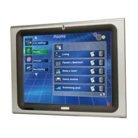
1.1 General Overview Figure 1-1: AFOLUX 9652 Series Touch Panel PC The AFL-15C-9652, AFL-17C-9652 and AFL-19C-9652 (AFL-9652 series) are Intel® Core™2 Duo or Intel® Celeron® M powered flat panel PCs with a rich variety of functions and peripherals. Both AFL-9652 models are designed for easy and simplified integration in to multiple applications. -
Page 21: Model Variations
Duo (T7500) Table 1-1: Model Variations 1.1.2 Standard Features Some of the standard features of the AFL-9652 series flat panel PC include: Rugged mechanism design with ABS/PC case IP 64 dustproof and waterproof front panel 1.0 GB / 2.0 GB DDR2 memory 802.11 a/b/g/n Wireless LAN... -
Page 22: External Overview
RS-232/422/485 port, a RS-232 port, an audio jack, power input and power switch. 1.2.1 Front Panel The front side of the AFL-9652 series is a flat panel TFT LCD screen surrounded by an ABS/PC plastic frame. Figure 1-2: Front View... -
Page 23: Rear Panel
Refer to Figure 1-3. Figure 1-3: AFL-9652 Rear View 1.2.3 Bottom Panel The bottom panel of the AFL-9652 series has the following I/O interfaces (Figure 1-4): 1 x 12 V DC power input connector 1 x Audio jack 1 x AT/ATX switch... -
Page 24: Internal Overview
Figure 1-4: AFL-9652 Bottom View 1.3 Internal Overview The AFL-9652 includes the following parts inside the aluminum internal cover. 1.0 GB DDR2 SO-DIMM Antennas Backlight inverter Bluetooth module CompactFlash® disk (optional) GPRS module (optional) Hard drive (optional) Two speakers Wireless LAN card Page 6... -
Page 25: Specifications
Figure 1-5: Internal Overview 1.4 Specifications 1.4.1 Preinstalled Hardware Components The AFL-9652 series flat panel PC has the following preinstalled components: 1 x Motherboard 1 x TFT LCD screen 1 x Touch screen panel 1 x Inverter 1 x Wireless LAN module... -
Page 26: System Specifications
1.4.2 System Specifications The technical specifications for the AFL-9652 series systems are listed in Table 1-2. SPECIFICATION 15 inch 17 inch 19 inch LCD Size 15” 17” 19” Max Resolution 1024 x 768 1280 x 1024 1280 x 1024 Brightness (cd/m... -
Page 27: Table 1-2: Afl-9652 Series System Specifications
Touch Screen Resistive Type 5 Wire (touch controller IC is on board) Power Input 12 V DC Power Consumption 80 W 86 W 88 W (Intel® T7500, 2 GB memory, 80 GB HDD) Table 1-2: AFL-9652 series System Specifications Page 9... -
Page 28: Specifications
Chapter Specifications Page 10... -
Page 29: Dimensions
2.1 Dimensions 2.1.1 AFL-15C-9652 Dimensions The dimensions of the AFL-15C-9652 flat panel PC are shown in Figure 2-1 below. Figure 2-1: AFL-15C-9652 Dimensions (units in mm) Page 11... -
Page 30: Afl-17C-9652 Dimensions
2.1.2 AFL-17C-9652 Dimensions The dimensions of the AFL-17C-9652 flat panel PC are shown in Figure 2-2 below. Figure 2-2: AFL-17C-9652 Dimensions (units in mm) Page 12... -
Page 31: Afl-19C-9652 Dimensions
2.1.3 AFL-19C-9652 Dimensions The dimensions of the AFL-19C-9652 flat panel PC are shown in Figure 2-2 below. Figure 2-3: AFL-19C-9652 Dimensions (units in mm) Page 13... -
Page 32: Intel® Desk-Top Processor Support
2.2 Intel® Desk-Top Processor Support A T7500 Intel® Socket P Core™2 Duo or a 550 Intel® Socket P Celeron® M processor is installed in the system. TheT7500 Intel® Core™2 Duo processor has a CPU speed of 2.2 GHz, a 800 MHz front side bus (FSB) and a 4.0 MB L2 cache. The 550 Intel® Celeron®... -
Page 33: Motherboard Components
The Intel® GME965 is capable of supporting two 200-pin 2.0 GB (max.) 400 MHz DDR2 SDRAM SO-DIMM (system max. 4.0 GB). If additional memory is required, please contact an IEI sales representative and discuss the necessary system requirement. 2.3.2 Storage Capacity The AFL-9652 comes with a SATA hard disk drive bay for a 2.5”... -
Page 34: External Peripheral Interface Connectors
2.4.2 LAN Connectivity The AFL-9652 series has two GbE connectors on the bottom panel. One of the external RJ-45 Ethernet LAN connectors is interfaced to an Intel® 82566MM Gigabit LAN connect device from the ICH8M Southbridge. The other RJ-45 Ethernet LAN connector is interfaced directly to an Intel®... -
Page 35: External Usb Connectors
Figure 2-7: RJ-45 Ethernet Connectors 2.4.3 External USB Connectors There are four USB 2.0 connectors on the bottom panel of the AFL-9652. All the USB 2.0 connectors are interfaced directly to the USB controllers on the ICH8M Southbridge. The USB connectors are all fully compliant with USB specification Revision 2.0 and USB specification Revision 1.1 and can be interfaced to both USB 1.1 and USB 2.0 compliant devices. -
Page 36: Afolux Afl-9652 Front Side
2.5 AFOLUX AFL-9652 Front Side 2.5.1 Monitor A LCD screen is installed on the front of the AFL-9652 series and connected to the LVDS connector on the motherboard. The screen is shown in Figure 2-10 below. Figure 2-10: LCD Screen 2.5.2 Touch-Screen Module... -
Page 37: Dual-Display
Figure 2-11: VGA Connector 2.6.2 Dual-Display The system supports dual display capabilities. An additional monitor can be connected to the AFL-9652 series through the VGA connector described above. 2.7 Audio 2.7.1 High Definition Audio Controller The integrated High Definition Audio compliant audio controller on the Intel® ICH8M Southbridge is integrated to a RealTek ALC262 audio codec. -
Page 38: System Power
Figure 2-13: Stereo Speakers 2.8 System Power 2.8.1 Power Mode The system can be run in the AT power mode or the ATX power mode. Both these power modes are described below. 2.8.1.1 ATX Power Mode (Default) With the ATX mode selected, the AFOLUX AFL-9652 panel PC goes in a standby mode when it is turned off. -
Page 39: At Power Mode
Figure 2-14: Power Connector 2.8.1.2 AT Power Mode With the AT mode selected, the power is controlled by a central power unit rather than a power switch. The AFOLUX AFL-9652 panel PC turns on automatically when the power is connected. The AT mode benefits a production line to control multiple panel PCs from a central management center and other applications including: Self-service kiosk Plant environment monitoring system... -
Page 40: Wireless Connections
2.9 Wireless Connections The following section describes the wireless modules on the circuit. 2.9.1 USB Bluetooth Module An integrated Bluetooth module is connected to ICH8M chipset through the USB bus. The AFL-9652 Bluetooth module enables wireless communications between the AFL-9652 and various peripheral devices through a Bluetooth network. -
Page 41: Wireless Ethernet
An optional GPRS module can be integrated into the AFL-9652 and provide the 2.5G mobile connectivity. The GPRS module is one of the OEM options for the AFL-9652 series. The technical specifications of the GPRS module are listed in the Appendix. -
Page 42: Unpacking
Chapter Unpacking Page 24... -
Page 43: Unpacking
3.1 Unpacking To unpack the flat panel PC, follow the steps below: WARNING! The front side LCD screen has a protective plastic cover stuck to the screen. Only remove the plastic cover after the flat panel PC has been properly installed. This ensures the screen is protected during the installation process. - Page 44 Quantity Item Image Standard AFL-9652 series panel PC Power adapter Power cord User manual CD and driver CD Touch pen eSATA cable Screw kit Optional Wall mounting kit Panel mounting kit Page 26...
- Page 45 Quantity Item Image 128 MB CompactFlash® card with Windows CE 5.0 pre-installed 128 MB CompactFlash® card with Windows CE 6.0 pre-installed 1 GB CompactFlash® card with Windows XPE pre-installed If any of these items are missing or damaged, contact the distributor or sales representative immediately.
-
Page 46: Installation
Chapter Installation Page 28... -
Page 47: Anti-Static Precautions
4.1 Anti-static Precautions WARNING: Failure to take ESD precautions during the maintenance of the AFL-9652 may result in permanent damage to the AFL-9652 and severe injury to the user. Electrostatic discharge (ESD) can cause serious damage to electronic components, including the AFL-9652. Dry climates are especially susceptible to ESD. It is therefore critical that whenever the AFL-9652 is accessed internally, or any other electrical component is handled, the following anti-static precautions are strictly adhered to. -
Page 48: Preinstalled Components
assisting with the procedure. Anti-static Discharge: If a user open the rear panel of the flat panel PC, to configure the jumpers or plug in added peripheral devices, ground themselves first and wear and anti-static wristband. 4.3 Preinstalled Components The following components are all preinstalled. Motherboard Backlight inverter TFT LCD screen... -
Page 49: Cf Card Installation
Step 7: 4.5 CF Card Installation The AFL-9652 series has one CompactFlash® Type I/II slot inside the left side panel. To install the CF card, follow the instructions below. Remove the retention screws (Figure 4-1) and lift the cover off the flat panel PC. -
Page 50: Hdd Installation
Insert a CF card into the slot (Figure 4-3). Step 3: Figure 4-3: CF Card Installation Replace the plastic back cover and fasten the retention screws. Step 4: Step 0: WARNING: Over-tightening back cover screws will crack the plastic frame. Maximum torque for cover screws is 5 kg-cm (0.36 lb-ft/0.49 Nm). -
Page 51: Figure 4-4: Aluminum Back Cover Retention Screws
Figure 4-4: Aluminum Back Cover Retention Screws Lift the aluminum cover to remove. Step 4: Remove the system fan on the top of the HDD bracket by removing the two Step 5: retention screws (Figure 4-5). Figure 4-5: System Fan Retention Screws Remove the remaining two HDD bracket retention screws (Figure 4-6) and lift Step 6: the HDD bracket off the panel PC. -
Page 52: Figure 4-6: Afl-9652 Hard Drive Bracket Retention Screws
Figure 4-6: AFL-9652 Hard Drive Bracket Retention Screws Attach the hard drive to the hard drive bracket. To do this, align the four retention Step 7: screw holes on the hard drive with the screw holes on the hard drive bracket. Fasten four flat head retention screws to secure the hard drive to the bracket (Figure 4-7). -
Page 53: At/Atx Mode Selection
Step 11: 4.7 AT/ATX Mode Selection AT and ATX power modes can both be used on the AFL-9652 series. The selection is made through an AT/ATX switch on the bottom panel (Figure 4-9). To select AT mode or ATX mode, follow the steps below. -
Page 54: Mounting The System
PC does not fall down and get damaged. The four methods of mounting the AFL-9652 series are listed below. Wall mounting... -
Page 55: Figure 4-10: Wall-Mounting Bracket
Carefully mark the locations of the four brackets screw holes on the wall. Step 2: Drill four pilot holes at the marked locations on the wall for the bracket retention Step 3: screws. Align the wall-mounting bracket screw holes with the pilot holes. Step 4: Secure the mounting-bracket to the wall by inserting the retention screws into Step 5:... -
Page 56: Figure 4-11: Chassis Support Screws
Figure 4-11: Chassis Support Screws NOTE: In the diagram below the bracket is already installed on the wall. Secure the panel PC by fastening the retention screw of the wall-mounting Step 9: bracket. (Figure 4-12).Step 0: Page 38... -
Page 57: Panel Mounting
Figure 4-12: Secure the Panel PC 4.8.2 Panel Mounting To mount the AFL-9652 series flat panel PC into a panel, please follow the steps below. Select the position on the panel to mount the flat panel PC. Step 1: Cut out a section from the panel that corresponds to the rear panel dimensions Step 2: of the flat panel PC. -
Page 58: Figure 4-13: Afl-15C-9652 Cutout Dimensions (Units In Mm)
Figure 4-13: AFL-15C-9652 Cutout Dimensions (units in mm) Figure 4-14: AFL-17C-9652 Cutout Dimensions (units in mm) Page 40... -
Page 59: Figure 4-15: Afl-19C-9652 Cutout Dimensions (Units In Mm)
Figure 4-15: AFL-19C-9652 Cutout Dimensions (units in mm) Slide the flat panel PC through the hole until the plastic frame is flush against the Step 3: panel. Insert the panel mounting clamps into the pre-formed holes along the edges of Step 4: the chassis, behind the plastic frame. -
Page 60: Arm Mounting
4.8.3 Arm Mounting The AFL-9652 series is VESA (Video Electronics Standards Association) compliant and can be mounted on an arm with a 100mm interface pad. To mount the AFL-9652 series on an arm, please follow the steps below. The arm is a separately purchased item. Please correctly mount the arm onto Step 1: the surface it uses as a base. -
Page 61: Cabinet And Rack Installation
PC. Step 0: 4.8.4 Cabinet and Rack Installation The AFL-9652 series flat panel PC can be installed into a cabinet or rack. The installation procedures are similar to the panel mounting installation. To do this, please follow the steps below:... -
Page 62: Figure 4-18: The Rack/Cabinet Bracket
AFL-9652 series flat panel PC and the rack/cabinet into which the AFL-9652 series is installed. Slide the rear of the AFL-9652 series flat panel PC through the rack/cabinet Step 1: bracket until the plastic frame is flush against the front of the bracket (Figure 4-18). -
Page 63: Figure 4-19: Secure The Rack/Cabinet Bracket
Figure 4-19: Secure the Rack/Cabinet Bracket Slide the flat panel PC with the attached rack/cabinet bracket into a rack or Step 4: cabinet (Figure 4-20). Figure 4-20: Install into a Rack/Cabinet Page 45... -
Page 64: Bottom Panel Connectors
Locate the RJ-45 connectors on the bottom panel of the AFL-9652 Series. Step 1: Align the connectors. Align the RJ-45 connector on the LAN cable with one of Step 2: the RJ-45 connectors on the bottom panel of the AFL-9652 series. See Figure 4-21. Figure 4-21: LAN Connection Page 46... -
Page 65: Serial Device Connection
RJ-45 connector into the onboard RJ-45 connector. Step 0: 4.9.2 Serial Device Connection The AFL-9652 Series has two single female DB-9 connectors on the bottom panel for a serial device. Follow the steps below to connect a serial device to the AFL-9652 Series panel PC. -
Page 66: Usb Device Connection
4.9.3 USB Device Connection There are four external USB 2.0 connectors. All connectors are perpendicular to the AFL-9652 series. To connect a USB 2.0 or USB 1.1 device, please follow the instructions below. Locate the USB connectors. The locations of the USB connectors are shown Step 1: in Chapter 2. -
Page 67: Vga Monitor Connection
4.9.4 VGA Monitor Connection The AFL-9652 has a single female DB-15 connector on the external peripheral interface panel. The DB-15 connector is connected to a CRT or VGA monitor. To connect a monitor to the AFL-9652, please follow the instructions below. Locate the female DB-15 connector. -
Page 68: System Maintenance
Chapter System Maintenance Page 50... -
Page 69: Introduction
5.1 Introduction If the components of the AFL-9652 series fail they must be replaced, such as the wireless LAN module or the motherboard. Please contact the system reseller or vendor to purchase the replacement parts. Back cover removal instructions and jumper settings for the AFL-9652 series are described below. -
Page 70: Memory Module Replacement
DDR2 memory module Wireless LAN module Inverter The internal aluminum back cover of the AFL-9652 series must be removed. To remove the aluminum back cover, remove the retention screws indicated in the sections below. Remove the following screws: 2 x Flat head screws 8 x Round head screws Screw positions are indicated below (Figure 5-1). -
Page 71: Figure 5-2: So-Dimm Socket Locations
Locate the DDR2 memory module on the motherboard of the flat panel PC Step 3: (Figure 5-2). Figure 5-2: SO-DIMM Socket Locations Remove the DDR2 memory module by pulling both the spring retainer clips Step 4: outward from the socket. Grasp the DDR2 memory module by the edges and carefully pull it out of the Step 5: socket. -
Page 72: Jumper Settings
The six jumpers listed below are located on the motherboard and can be setup for AFL-9652 series. Clear CMOS jumper (J_CMOS1) COM1 and COM3 RI and voltage select (J10) COM3 RS-232/422/485 select (J9) CompactFlash®... -
Page 73: Clear Cmos Jumper (J_Cmos1)
5.5.1 Clear CMOS Jumper (J_CMOS1) The Clear CMOS jumper setting is used to reset the CMOS to default settings. J_CMOS1 Description Normal Operation Clear CMOS Setup Table 5-1: Clear CMOS Jumper Settings 5.5.2 COM1 RI and Voltage Select (J10) The COM1 pin-9 signal can be selected as 12V, 5V or Ring. Description Use for RI 12 V... -
Page 74: Com3 Mode Select
5.5.4 COM3 Mode Select The following jumper selects RS-232, RS-422 or RS-485 mode for the COM3 serial port. Description RS-422 TX- RS-485 D- RS-422 TX+ RS-485 D+ Table 5-4: COM3 RS-422/485 Selection Description Short 1-2 DCD3 (RS-232) Short 2-3 TX3- (RS-422/485) Short 4-5 RXD3 (RS-232) Short 5-6... -
Page 75: Com3 Rs-422 And Rs-485 Pinouts
5.5.4.1 COM3 RS-422 and RS-485 Pinouts The pinouts for RS-422 and RS-485 operation of external serial port COM 3 are detailed below. COM 3 RS-422 Description Pin 1 Pin 2 Pin 6 Pin 7 Table 5-7: RS-422 Pinouts COM 3 RS-485 Description Pin 1 Data-... -
Page 76: Ami Bios Setup
Chapter AMI BIOS Setup Page 58... -
Page 77: Introduction
6.1 Introduction A licensed copy of AMI BIOS is preprogrammed into the ROM BIOS. The BIOS setup program allows users to modify the basic system configuration. This chapter describes how to access the BIOS setup program and the configuration options that may be changed. -
Page 78: Getting Help
F1 key General help, only for Status Page Setup Menu and Option Page Setup Menu F2 /F3 key Change color from total 16 colors. F2 to select color forward. F10 key Save all the CMOS changes, only for Main Menu Table 6-1: BIOS Navigation Keys 6.1.3 Getting Help When F1 is pressed a small help window describing the appropriate keys to use and the... -
Page 79: Main
6.2 Main The Main BIOS menu (BIOS Menu 1) appears when the BIOS Setup program is entered. The Main menu gives an overview of the basic system information. BIOS Menu 1: Main System Overview The System Overview lists a brief summary of different system components. The fields in System Overview cannot be changed. -
Page 80: Advanced
Lists memory size Size: The System Overview field also has two user configurable fields: System Time [xx:xx:xx] Use the System Time option to set the system time. Manually enter the hours, minutes and seconds. System Date [xx/xx/xx] Use the System Date option to set the system date. Manually enter the day, month and year. -
Page 81: Cpu Configuration
BIOS Menu 2: Advanced 6.3.1 CPU Configuration Use the CPU Configuration menu (BIOS Menu 3) to view detailed CPU specifications and configure the CPU. Page 63... -
Page 82: Menu 3: Cpu Configuration
BIOS Menu 3: CPU Configuration The CPU Configuration menu (BIOS Menu 3) lists the following CPU details: Manufacturer: Lists the name of the CPU manufacturer Brand String: Lists the brand name of the CPU being used Frequency: Lists the CPU processing speed FSB Speed: Lists the FSB speed Cache L1: Lists the CPU L1 cache size Cache L2: Lists the CPU L2 cache size... -
Page 83: Ide Configuration
6.3.2 IDE Configuration Use the IDE Configuration menu (BIOS Menu 4) to change and/or set the configuration of the IDE devices installed in the system. BIOS Menu 4: IDE Configuration ATA/IDE Configurations [Compatible] Use the ATA/IDE Configurations option to configure the ATA/IDE controller. Disables the on-board ATA/IDE controller. -
Page 84: Ide Master, Ide Slave
storage devices. Some legacy OS do not support this mode. Legacy IDE Channels [SATA Only] SATA Only EFAULT SATA Pri., PATA Sec PATA Only IDE Master and IDE Slave When entering setup, BIOS auto detects the presence of IDE devices. BIOS displays the status of the auto detected IDE devices. -
Page 85: Menu 5: Ide Master And Ide Slave Configuration
BIOS Menu 5: IDE Master and IDE Slave Configuration Type [Auto] Use the Type BIOS option select the type of device the AMIBIOS attempts to boot from after the Power-On Self-Test (POST) is complete. BIOS is prevented from searching for an IDE disk Not Installed drive on the specified channel. -
Page 86: Zip
IDE disk drives on the specified channel. This option specifies an ATAPI Removable Media ARMD Device. These include, but are not limited to: LS-120 LBA/Large Mode [Auto] Use the LBA/Large Mode option to disable or enable BIOS to auto detects LBA (Logical Block Addressing). -
Page 87: Pio Mode [Auto]
PIO Mode [Auto] Use the PIO Mode option to select the IDE PIO (Programmable I/O) mode program timing cycles between the IDE drive and the programmable IDE controller. As the PIO mode increases, the cycle time decreases. BIOS auto detects the PIO mode. Use this value if the IDE disk Auto EFAULT drive support cannot be determined. -
Page 88: Auto]
Multi Word DMA mode 0 selected with a maximum data MWDMA0 transfer rate of 4.2MBps Multi Word DMA mode 1 selected with a maximum data MWDMA1 transfer rate of 13.3MBps Multi Word DMA mode 2 selected with a maximum data MWDMA2 transfer rate of 16.6MBps Ultra DMA mode 0 selected with a maximum data transfer... -
Page 89: Super Io Configuration
BIOS auto detects HDD SMART support. Auto EFAULT Prevents BIOS from using the HDD SMART feature. Disabled Allows BIOS to use the HDD SMART feature Enabled 32Bit Data Transfer [Enabled] Use the 32Bit Data Transfer BIOS option to enables or disable 32-bit data transfers. Prevents the BIOS from using 32-bit data transfers. -
Page 90: Serial Port1 Address [3F8/Irq4]
Serial Port1 Address [3F8/IRQ4] Use the Serial Port1 Address option to select the Serial Port 1 base address. No base address is assigned to Serial Port 1 Disabled Serial Port 1 I/O port address is 3F8 and the interrupt 3F8/IRQ4 EFAULT address is IRQ4 Serial Port 1 I/O port address is 3E8 and the interrupt... -
Page 91: Hardware Health Configuration
Serial port 3 I/O port address is 2F8 Serial port 3 I/O port address is 3E8 EFAULT Serial port 3 I/O port address is 2E8 Serial Port3 IRQ [10] Use the Serial Port3 IRQ option to select the interrupt address for serial port 3. Serial port 3 IRQ address is 10 EFAULT Serial Port4 Address [2E8]... -
Page 92: Menu 7: Hardware Health Configuration
BIOS Menu 7: Hardware Health Configuration FAN Mode Setting [Full On Mode] Use the FAN Mode Setting option to configure the CPU fan or system fans. Fan is on all the time Full On Mode EFAULT Fan is off when the temperature is low Automatic mode enough. -
Page 93: Cpu Temp. Limit Of Off [000]
When the CPU FAN Mode Setting option is in the PWM Manual Mode, the following parameters can be set. CPU Fan PWM control CPU Temp. Limit of OFF [000] WARNING: Setting this value too high may cause the fan to stop when the CPU is at a high temperature and therefore cause the system to be damaged. -
Page 94: Cpu Fan Start Pwm [070]
starts, it rotates using the starting pulse width modulation (PWM) specified in the Fan 3 Start PWM option below. To select a value, select the CPU Temp. Limit of Start option and enter a decimal number between 000 and 127. The temperature range is specified below. -
Page 95: Cpu Fan Pwm Control [070]
CPU Fan PWM Control [070] The CPU Fan PWM Control option can only be set if the CPU FAN Mode Setting option is set to Manual Mode. Use the CPU Fan PWM Control option to select PWM duty cycle control. The PWM duty cycle specifies the width of the modulated pulse. A high value ensures a wide pulse and a low value ensures a narrow pulse. -
Page 96: Intel Amt Configuration
6.3.5 Intel AMT Configuration The Intel AMT Configuration menu (BIOS Menu 8) configures the Intel® Active Management Technology (AMT) options. BIOS Menu 8: Intel AMT Configuration Intel AMT Support [Disabled] Use the Intel AMT Support option to enable or disable the Intel AMT support. The Intel®... -
Page 97: Menu 9: Me Subsystem Configuration
BIOS Menu 9: Me Subsystem Configuration BootBlock HECI Message [Enabled] Use the BootBlock HECI Message option to enable or disable HECI message when booting up the system. The HECI message is disabled when booting up the Disabled system. The HECI message is enabled when booting up the Enabled EFAULT system. -
Page 98: End Of Post S5 Heci Message [Enabled]
The HECI message enabled. Enabled EFAULT End Of Post S5 HECI Message [Enabled] Use the End Of Post S5 HECI Message option to enable or disable HECI message when the system is in the off (S5) state. The HECI message is disabled when the system is off. Disabled The HECI message enabled when the system is off. -
Page 99: Intel Robson Configuration
interface of a managed client system, such as BIOS menu, is displayed through the management system. 6.3.6 Intel Robson Configuration The Intel Robson Configuration menu (BIOS Menu 10) allows the Intel® Robson Technology option to be configured. BIOS Menu 10: Intel Robson Configuration Intel Robson [Disabled] Use the Intel Robson BIOS option to enable or disable the Intel®... -
Page 100: Remote Access Configuration
6.3.7 Remote Access Configuration Use the Remote Access Configuration menu (BIOS Menu 11) to configure remote access parameters. The Remote Access Configuration is an AMIBIOS feature and allows a remote host running a terminal program to display and configure the BIOS settings. -
Page 101: Serial Port Number
Serial Port Number Serial Port Mode Redirection after BIOS POST Terminal Type These configuration options are discussed below. Serial Port Number [COM1] Use the Serial Port Number option allows users to select the serial port used for remote access. System is remotely accessed through COM1 COM1 EFAULT System is remotely accessed through COM2... -
Page 102: Redirection After Bios Post [Always]
57600 8,n,1 38400 8,n,1 19200 8,n,1 09600 8,n,1 NOTE: Identical baud rate setting musts be set on the host (a management computer running a terminal software) and the slave Redirection After BIOS POST [Always] Use the Redirection After BIOS POST option to specify when console redirection should occur. -
Page 103: Usb Configuration
6.3.8 USB Configuration Use the USB Configuration menu (BIOS Menu 12) to read USB configuration information and configure the USB settings. BIOS Menu 12: USB Configuration USB Configuration The USB Configuration field shows the system USB configuration. The items listed are: Module Version: x.xxxxx.xxxxx USB Devices Enabled The USB Devices Enabled field lists the USB devices that are enabled on the system... -
Page 104: Usb 2.0 Controller [Enabled]
USB function support enabled Enabled EFAULT USB 2.0 Controller [Enabled] Use the USB 2.0 Controller BIOS option to enable or disable the USB 2.0 controller USB 2.0 controller disabled Disabled USB 2.0 controller enabled Enabled EFAULT Legacy USB Support [Enabled] Use the Legacy USB Support BIOS option to enable USB mouse and USB keyboard support. -
Page 105: Power Configuration
6.3.9 Power Configuration Use the Power Configuration menu (BIOS Menu 13) configures the Advanced Configuration and Power Interface (ACPI) and Power Management (APM) options. BIOS Menu 13: Power Configuration 6.3.9.1 ACPI Configuration The ACPI Configuration menu (BIOS Menu 8) configures the Advanced Configuration and Power Interface (ACPI) option. -
Page 106: Apm Configuration
BIOS Menu 14: ACPI Configuration [Advanced\ Power Configuration] Suspend Mode [S1(POS)] Use the Suspend Mode option to specify the sleep state the system enters when it is not being used. The system enters S1(POS) sleep state. The system S1 (POS) EFAULT appears off. -
Page 107: Menu 15:Advanced Power Management Configuration
BIOS Menu 15:Advanced Power Management Configuration Power Button Mode [On/Off] Use the Power Button Mode BIOS to specify how the power button functions. When the power button is pressed the system is either On/Off EFAULT turned on or off When the power button is pressed the system goes into Suspend suspend mode Restore on AC Power Loss [Last State]... -
Page 108: Resume On Ring [Disabled]
turns itself on. If it was off, it remains off. Resume on Ring [Disabled] Use the Resume on Ring BIOS option to enable activity on the RI (ring in) modem line to rouse the system from a suspend or standby state. That is, the system will be roused by an incoming call on a modem. -
Page 109: Pci/Pnp
After setting the alarm, the computer turns itself on from a suspend state when the alarm goes off. Resume on Keyboard/Mouse [Disabled] Use the Resume on Keyboard/Mouse BIOS option to enable activity on either the keyboard or mouse to rouse the system from a suspend or standby state. That is, the system is roused when the mouse is moved or a button on the keyboard is pressed. -
Page 110: Menu 16: Pci/Pnp Configuration
BIOS Menu 16: PCI/PnP Configuration IRQ# Use the IRQ# address to specify what IRQs can be assigned to a particular peripheral device. The specified IRQ is available to be used by Available PCI/PnP devices The specified IRQ is reserved for use by Legacy ISA Reserved devices Available IRQ addresses options are:... -
Page 111: Dma Channel# [Available]
IRQ9 IRQ10 IRQ 11 IRQ 14 IRQ 15 DMA Channel# [Available] Use the DMA Channel# option to assign a specific DMA channel to a particular PCI/PnP device. The specified DMA is available to be used by Available EFAULT PCI/PnP devices The specified DMA is reserved for use by Legacy Reserved ISA devices... -
Page 112: Boot
54KB reserved for legacy ISA devices 6.5 Boot Use the Boot menu (BIOS Menu 17) to configure system boot options. BIOS Menu 17: Boot GbE LAN Boot (82566MM) [Disabled] Use the GbE LAN Boot (82566MM) option to enable the Intel® 82566MM GbE controller to boot the system. -
Page 113: Boot Settings Configuration
Boot From LAN Support (82573L) [Disabled] Use the BOOT From LAN Support (82573L) option to enable the Intel® 82573L PCIe GbE controller to boot the system. Cannot be booted from a remote system through the Disabled EFAULT Intel® 82573L PCIe GbE controller Can be booted from a remote system through the Enabled Intel®... -
Page 114: Quick Boot [Enabled]
Quick Boot [Enabled] Use the Quick Boot BIOS option to make the computer speed up the boot process. No POST procedures are skipped Disabled Some POST procedures are skipped to decrease Enabled EFAULT the system boot time Quiet Boot [Disabled] Use the Quiet Boot BIOS option to select the screen display when the system boots. -
Page 115: Boot Device Priority
located on the upper left-hand corner of the 10-key pad. The Number Lock LED on the keyboard lights up when the Number Lock is engaged. Allows the Number Lock on the keyboard to be enabled EFAULT automatically when the computer system boots up. This allows the immediate use of the 10-key numeric keypad located on the right side of the keyboard. -
Page 116: Security
BIOS Menu 19: Boot Device Priority Settings 6.6 Security Use the Security menu (BIOS Menu 20) to set system and user passwords. BIOS Menu 20: Security Change Supervisor Password Use the Change Supervisor Password to set or change a supervisor password. The default for this option is Not Installed. -
Page 117: Chipset
6.7 Chipset Use the Chipset menu to access the NorthBridge, SouthBridge and ME Subsystem configuration menus. WARNING! Setting the wrong values for the Chipset BIOS selections in the Chipset BIOS menu may cause the system to malfunction. BIOS Menu 21: Chipset Configuration 6.7.1 North Bridge Configuration Use the North Bridge Chipset Configuration menu (BIOS Menu 22) to configure the Northbridge chipset. -
Page 118: Menu 22: Chipset Configuration
BIOS Menu 22: Chipset Configuration Memory Remap Feature [Enabled] Use the Memory Remap Feature option to allow the overlapped PCI memory above the total physical memory to be remapped. Overlapped PCI memory can be remapped Enabled EFAULT Overlapped PCI memory cannot be remapped Disabled Memory Hole [Disabled] Use the Memory Hole option to reserve memory space between 15MB and 16MB for ISA... -
Page 119: Internal Graphics Mode Select [Enable, 8Mb]
ISA expansion cards Internal Graphics Mode Select [Enable, 8MB] Use the Internal Graphic Mode Select option to specify the amount of system memory that can be used by the Internal graphics device. Disable 1MB of memory used by internal graphics device Enable, 1MB 8MB of memory used by internal graphics device Enable, 8MB... -
Page 120: South Bridge Configuration
6.7.2 South Bridge Configuration The South Bridge Configuration menu (BIOS Menu 23) allows the Southbridge chipset to be configured. BIOS Menu 23:Southbridge Chipset Configuration HDA Controller [Enabled] Use the HDA Controller option to enable the Southbridge high definition audio controller. If the HDA device has been connected to the system, this option should be enabled. -
Page 121: Exit
The system will not communicate with a remote Disabled management server. The Alert Standard Format (ASF) controller is activated Enabled EFAULT and can communicate with a remote management server. 6.8 Exit Use the Exit menu (BIOS Menu 24) to load default BIOS values, optimal failsafe values and to save configuration changes. -
Page 122: Discard Changes And Exit
Discard Changes and Exit Use the Discard Changes and Exit option to exit the BIOS configuration setup program without saving the changes made to the system. Discard Changes Use the Discard Changes option to discard the changes and remain in the BIOS configuration setup program. -
Page 123: Software Drivers
Chapter Software Drivers Page 105... -
Page 124: Available Software Drivers
NOTE: The content of the CD may vary throughout the life cycle of the product and is subject to change without prior notice. Visit the IEI website or contact technical support for the latest updates. The following drivers can be installed on the system: Intel®... -
Page 125: Figure 7-1: Intel® Chipset Driver Directory
Figure 7-1: Intel® Chipset Driver Directory Click on the directory icon in Figure 7-1. Step 3: The window in Figure 7-2 appears. Step 4: Figure 7-2: Intel® Chipset Driver Setup Icon Page 107... -
Page 126: Figure 7-3: Intel® Package Manager
Click on the infinst_autol setup icon in Figure 7-2. Step 5: The Intel® Package Manager begins to extract the installation files. See Figure Step 6: 7-3. Figure 7-3: Intel® Package Manager The Intel® Setup Welcome screen. See Figure 7-4. Step 7: Page 108... -
Page 127: Figure 7-4: Intel® Setup Welcome Screen
Figure 7-4: Intel® Setup Welcome Screen Click N to continue. Step 8: The Intel® license agreement in appears. Step 9: Figure 7-5: Intel® Chipset Driver License Agreement Accept the terms and conditions by clicking Y Step 10: Page 109... -
Page 128: Figure 7-6: Readme File
The Readme file in Figure 7-6 appears. Step 11: Figure 7-6: Readme File Click N to continue. Step 12: The driver is then installed. Step 13: When the installation process is complete, the Setup Complete screen appears. Step 14: See Figure 7-7. Page 110... -
Page 129: Intel® Graphics Media Accelerator Driver
Figure 7-7: Intel® Chipset Driver Complete Installation Screen To complete the chipset driver installation, click F Step 15: Step 0: INISH 7.3 Intel® Graphics Media Accelerator Driver To install the chipset driver, please follow the steps below: Select the VGA driver from the driver CD menu. Step 1: A new window opens. -
Page 130: Figure 7-8: Select The Operating System
Figure 7-8: Select the Operating System Select the operating system from those shown in Figure 7-8. Step 3: A new window appears. See Figure 7-9. Step 4: Figure 7-9: Intel® Driver Directory Page 112... -
Page 131: Figure 7-10: Intel® Vga Driver Setup Icon
Click the directory icon in Figure 7-9. Step 5: A new window appears. See Figure 7-10. Step 6: Figure 7-10: Intel® VGA Driver Setup Icon Click on the VGA driver installation icon in See Figure 7-10. Step 7: The Readme information file shown in Figure 7-11 appears. Step 8: Page 113... -
Page 132: Figure 7-11: Gma Driver Readme File
Figure 7-11: GMA Driver Readme File Click N to extract the GMA driver files. See Figure 7-12. Step 9: Figure 7-12: GMA Driver File Extraction The welcome screen shown in Figure 7-13 appears. Step 10: Page 114... -
Page 133: Figure 7-13: Gma Driver Installation Welcome Screen
Figure 7-13: GMA Driver Installation Welcome Screen To continue the installation process, click N Step 11: The license agreement in Figure 7-14 appears. Step 12: Figure 7-14: GMA Driver License Agreement Click the Y in Figure 7-14 to continue. Step 13: Page 115... -
Page 134: Intel® 82566 Gigabit Lan Connect Device Driver
The installation notice shown in Figure 7-15 appears. Step 14: Figure 7-15: GMA Driver Installing Notice A confirmation screen shown in Figure 7-16 appears. Step 15: Figure 7-16: GMA Driver Installation Complete After selecting when to restart the computer in Figure 7-16, click F Step 16: Step 0: INISH... -
Page 135: Figure 7-17: Intel® 82566 Driver Directory Icon
Figure 7-17: Intel® 82566 Driver Directory Icon Click on the Intel® 82566DM, MM directory icon in Figure 7-17. Step 3: The window in Figure 7-18 appears. Step 4: Page 117... -
Page 136: Figure 7-18: Intel® 82566 Operating System
Figure 7-18: Intel® 82566 Operating System Select the Operating System in Figure 7-18. Step 5: The window in Figure 7-19appears. Step 6: In Figure 7-19 select the operating system type installed on the system. Step 7: Page 118... -
Page 137: Figure 7-19: Select Operating System Type
Figure 7-19: Select Operating System Type The window in Figure 7-20 appears. Step 8: Figure 7-20: Driver Directory Click on the directory icon in Figure 7-20. Step 9: Page 119... -
Page 138: Figure 7-21: Intel® 82566 Device Driver Startup Icon
A window containing the Intel® 82566 driver startup icon appears. See Figure Step 10: 7-21. Figure 7-21: Intel® 82566 Device Driver Startup Icon Double click the Intel® 82566 driver startup icon in Figure 7-21. Step 11: The driver begins to extract the installation files. Step 12: The Welcome screen in Figure 7-22 appears next. -
Page 139: Figure 7-22: Intel® 82566 Welcome Screen
Figure 7-22: Intel® 82566 Welcome Screen The license agreement in Figure 7-23 appears. Step 15: Figure 7-23: Intel® 82566 Driver License Agreement Accept the conditions of the license agreement and click N to continue. Step 16: The Setup Options screen in Figure 7-24 appears next. Step 17: Page 121... -
Page 140: Figure 7-24: Intel® 82566 Driver Setup Options
Figure 7-24: Intel® 82566 Driver Setup Options Select the required installation configuration in Figure 7-24 and click N Step 18: continue. The Ready to Install the Program window in Figure 7-25 appears. Step 19: Figure 7-25: Intel® 82566 Driver Installation Ready Window Click I in Figure 7-25. -
Page 141: Intel® 82573 Pci Express Gigabit Ethernet Controller Driver
Figure 7-26: Intel® 82566 Driver Installation Progress When the installation is finished. Click F in the termination screen. Step 22: Step 0: INISH 7.5 Intel® 82573 PCI Express Gigabit Ethernet Controller Driver To install the Intel® 82573 PCIe GbE controller, please follow the steps below. Select LAN from the driver CD menu. -
Page 142: Figure 7-27: Intel® 82573 Driver Directory Icon
Figure 7-27: Intel® 82573 Driver Directory Icon Click on the Intel® 82573L directory icon in Figure 7-27. Step 3: The window in Figure 7-28 appears. Step 4: Page 124... -
Page 143: Figure 7-28: Intel® 82573 Operating System
Figure 7-28: Intel® 82573 Operating System Select the Operating System in Figure 7-28. Step 5: The window in Figure 7-29 appears. Step 6: In Figure 7-29 select the operating system type installed on the system. Step 7: Page 125... -
Page 144: Figure 7-29: Select Operating System Type
Figure 7-29: Select Operating System Type The window in Figure 7-30 appears. Step 8: Figure 7-30: Driver Directory Click on the directory icon in Figure 7-20. Step 9: Page 126... -
Page 145: Figure 7-31: Intel® 82573 Driver Startup Icon
A window containing the Intel® 82573 driver startup icon appears. See Figure Step 10: 7-30. Figure 7-31: Intel® 82573 Driver Startup Icon Click the startup icon in Figure 7-31. Step 11: The License Agreement for the Intel® 82573 appears. See Figure 7-32. Step 12: Page 127... -
Page 146: Figure 7-32: Intel® 82573 License Agreement
Figure 7-32: Intel® 82573 License Agreement Accept the license terms and agreements in and click N to continue. Step 13: Next, select the directory in which the files must be saved. See Figure 7-33. Step 14: Figure 7-33: Intel® 82573 File Location Select Click N to continue. -
Page 147: Figure 7-34: Intel® 82573 Installation Files Extraction
The driver begins to extract the installation files. See Figure 7-34. Step 16: Figure 7-34: Intel® 82573 Installation Files Extraction The Intel® PRO Network Connections window appears. See Figure 7-35. Step 17: Figure 7-35: Intel® PRO Network Connections window Click I in Figure 7-35. -
Page 148: Figure 7-36: Intel® Pro Network Connections Welcome
The Intel® PRO Network Connections Welcome screen in Figure 7-36 Step 19: appears. Figure 7-36: Intel® PRO Network Connections Welcome Click N to continue. Step 20: A new License Agreement appears. See Figure 7-37. Step 21: Figure 7-37: License Agreement Accept the terms and conditions in Figure 7-37 and click N to continue. -
Page 149: Figure 7-38: Setup Type
The Setup Type window in Figure 7-38 appears. Step 23: Figure 7-38: Setup Type Select the setup type in Figure 7-38 and click N to continue. Step 24: The drivers are installed. See Figure 7-39. Step 25: Figure 7-39: Intel® 82573 Driver Installation Progress When the driver is installed. -
Page 150: Realtek Hd Audio Driver (Alc883) Installation
7.6 Realtek HD Audio Driver (ALC883) Installation To install the Realtek High Definition (HD) Audio driver, please follow the steps below. NOTE: This driver only needs to be installed if an external audio kit with a RealTek ALC883 codec is installed. 7.6.1 BIOS Setup Enter the BIOS setup. -
Page 151: Figure 7-40: Select The Audio Codec
Figure 7-40: Select the Audio CODEC Double-click the ALC883 folder. Step 3: Double-click the appropriate operating system folder (Figure 7-41). Step 4: Page 133... -
Page 152: Figure 7-41: Select The Os
Figure 7-41: Select the OS Double-click the appropriate operating system version folder (Figure 7-42). Step 5: Figure 7-42: Select the OS Version Double-click the Setup.exe program icon in Figure 7-43. Step 6: Page 134... -
Page 153: Figure 7-43: Locate The Setup Program Icon
Figure 7-43: Locate the Setup Program Icon The InstallShield Wizard starts (Figure 7-44). Step 7: Figure 7-44: The InstallShield Wizard Starts The InstallShield Wizard is prepared to guide the user through the rest of the Step 8: process (Figure 7-45). Page 135... -
Page 154: Figure 7-45: Preparing Setup Screen
Figure 7-45: Preparing Setup Screen Once initialized, the InstallShield Wizard welcome screen appears Step 9: (Figure 7-46). Figure 7-46: InstallShield Wizard Welcome Screen Click N to continue the installation. Step 10: InstallShield starts to install the new software as shown in Figure 7-47. Step 11: Page 136... -
Page 155: Figure 7-47: Audio Driver Software Configuration
Figure 7-47: Audio Driver Software Configuration The Installation Wizard updates the system as shown in Figure 7-48. Step 12: Figure 7-48: Installation Wizard Updates the System After the driver installation process is complete, a confirmation screen appears Step 13: (Figure 7-49). Page 137... -
Page 156: Intel ® Matrix Storage Manager Driver Installation
Figure 7-49: Restart the Computer The confirmation screen offers the option of restarting the computer now or later. Step 14: For the settings to take effect, the computer must be restarted. Click F INISH restart the computer. Step 0: ® 7.7 Intel Matrix Storage Manager Driver Installation To install the Intel®... -
Page 157: Figure 7-50: Sata Raid Driver Installation Program
Figure 7-50: SATA RAID Driver Installation Program Double-click the INTEL® folder. Step 3: Double-click the iata62_cd.exe program icon in Figure 7-51. Step 4: Page 139... -
Page 158: Figure 7-51: Sata Raid Setup Program Icon
Figure 7-51: SATA RAID Setup Program Icon Figure 7-52 shows the InstallShield Wizard preparing to guide the user Step 5: through the rest of the process. Figure 7-52: InstallShield Wizard Setup Screen Page 140... -
Page 159: Figure 7-53: Matrix Storage Manager Setup Screen
Figure 7-53 shows the Matrix Storage Manager software configuring the Step 6: installation process. Figure 7-53: Matrix Storage Manager Setup Screen Figure 7-54 shows the Matrix Storage Manager welcome screen. Step 7: Figure 7-54: Matrix Storage Manager Welcome Screen Page 141... -
Page 160: Figure 7-55: Matrix Storage Manager Warning Screen
Click N and a warning appears (Figure 7-55). Read the warning carefully Step 8: and decide whether or not to continue the installation process. Figure 7-55: Matrix Storage Manager Warning Screen Click N and a license agreement appears (Figure 7-56). Step 9: Figure 7-56: Matrix Storage Manager License Agreement Page 142... -
Page 161: Figure 7-57: Matrix Storage Manager Readme File
Read the license agreement. To accept the terms and conditions stipulated in Step 10: the license agreement shown, click Y and the Readme information file shown in Figure 7-57 appears. Figure 7-57: Matrix Storage Manager Readme File Read the Readme file information and click N Step 11: After the driver installation process is complete, a confirmation screen appears Step 12:... -
Page 162: Intel® Active Management Technology Driver Installation
Figure 7-58: Matrix Storage Manager Setup Complete The confirmation screen offers the option of restarting the computer now or later. Step 13: For the settings to take effect, the computer must be restarted. Click F INISH restart the computer. Step 0: 7.8 Intel®... -
Page 163: Figure 7-59: Iamt Driver Directory
Figure 7-59: IAMT Driver Directory Click on the LMS_SOL directory icon. The window in Figure 7-60 appears. Step 3: Figure 7-60: IAMT Driver Installation Icon Double click the setup icon in Figure 7-60. Step 4: Page 145... -
Page 164: Figure 7-61: Iamt Welcome Screen
The window in Figure 7-61 appears. Step 5: Figure 7-61: IAMT Welcome Screen Click N to continue. The License Agreement in Figure 7-62 appears. Step 6: Figure 7-62: IAMT License Agreement Agree to the terms and conditions in the license agreement by clicking Y Step 7: Page 146... -
Page 165: Figure 7-63: Iamt Readme File
The IAMT Readme file in Figure 7-63 appears Step 8: Figure 7-63: IAMT Readme File Click N to continue. Step 9: Setup operations are performed. See Figure 7-64. Step 10: Figure 7-64: IAMT Setup Operations Page 147... -
Page 166: Figure 7-65: Completed Installation
When the Setup Operations in Figure 7-64 are complete, the window in Figure Step 11: 7-65 appears. Figure 7-65: Completed Installation Click F to complete the IAMT installation. Step 12: INISH Go back to iAMT and Utilities directory (Figure 7-66). Step 13: Figure 7-66: IAMT Driver Directory Page 148... -
Page 167: Figure 7-67: Heci Driver Installation Icon
Click on the HECI directory icon. The window in Figure 7-67 appears. Step 14: Figure 7-67: HECI Driver Installation Icon Double click the setup icon in Figure 7-67. Step 15: Follow the step-by-step installation process to install the HECI driver. Step 16: Step 0: Step 0:... -
Page 168: Intel Amt Configuration
Chapter ® Intel Configuration Page 150... -
Page 169: Intel ® Amt Setup Procedure
® 8.1 Intel AMT Setup Procedure The AFL-9652 series is featured with the Intel® Active Management Technology (AMT) 2.5. To enable the Intel® AMT function, follow the steps below. Make sure the DIMM1 socket is installed with one DDR2 SO-DIMM. -
Page 170: Intel ® Management Engine Bios Extension
A screen prompts the user to press <Ctrl+P> after a single beep during boot-up Step 1: process. To get into the Intel® MEBx settings, press <Ctrl+P>. Enter the Intel® current ME password as it requires (Figure 8-2). Enter the IEI Step 2: factory ME password: Abab12!@ (the Intel® default password is admin). -
Page 171: Figure 8-3: Change Intel® Me Password
To change the password, select Change Intel® ME Password. Enter a new Step 3: password following the strong password rule (containing at least one upper case letter, one lower case letter, one digit and one special character, and be at least eight characters). -
Page 172: Figure 8-6: Provision Model
Figure 8-6: Provision Model When the screen in Figure 8-7 prompts, enter N and press Enter. Step 7: Figure 8-7: Intel® AMT 2.0 Mode A message prompts to confirm to Change to Small Business (Figure 8-8). Enter Step 8: Y and press Enter. Page 154... -
Page 173: Figure 8-8: Enterprise
Figure 8-8: Enterprise Select TCP/IP (in Intel AMT Configuration) and press Enter. A message prompts Step 9: for disabling network interface. Enter N to enable network interface. Figure 8-9: Enable Network Interface Page 155... -
Page 174: Figure 8-10: Exit
Enable or disable DHCP. DHCP is enabled by default. If DHCP is disabled, enter Step 10: the following TCP/IP settings: Static TCP/IP address (the static TCP/IP address and Intel® AMI Host Name must be different from those configured in the operating system) Subnet mask Default Gateway address (optional) Preferred Domain Naming Services (DNS) serer address (optional) -
Page 175: Using The Intel Amt Web Interface
® 8.3 Using the Intel AMT Web Interface NOTE: Prior to use the Intel® AMT web interface, please make sure the Intel® AMT drivers are properly installed in the AFL-9652 and the Intel® AMT enabled confirmation dialog window displays after boot-up. To access an Intel®... -
Page 176: Figure 8-12: Intel® Amt Web Login Dialog
Figure 8-12: Intel® AMT Web Login Dialog Enter admin as the user name (Figure 8-12). Step 6: Enter the password changed in the Intel® MEBx configuration (Section 8.2, Step 7: 3). If the password remained as default, enter Abab12!@ Step Press OK and the Intel®... -
Page 177: Figure 8-13: Intel® Amt Web Interface
Figure 8-13: Intel® AMT Web Interface NOTE: To enhance the platform manageability of the AFL-9652, work with the Independent Software Vendors (ISV) to implement the Intel® AMT management utility on the system. Page 159... -
Page 178: System Specifications
Appendix System Specifications Page 160... -
Page 179: Motherboard Specifications
A.1 Motherboard Specifications The AFL-9652 series come with an AFLMB-9652 motherboard pre-installed. The technical specifications of the motherboard are listed in Table 8-1. Specification AFLMB-9652 2.0 GHz Intel® Celeron M 550/2.2 GHz Intel® Core™2 Duo T7500 System Chipset Intel® GME965... -
Page 180: Flat Panel Screen Specifications
A.2 Flat Panel Screen Specifications The AFL-9652 series come with a TFT LCD monitor at the front of the flat panel PC. The specifications for the LCD monitor are shown in Table 8-2 below. SPECIFICATION 15 inch 17 inch 19 inch Panel Type G150XG01 V.1 / AUO... -
Page 181: Touch Screen Specifications
A.3 Touch Screen Specifications The AFL-9652 series come with an analog resistive type touch panel. Table 8-3 lists the touch panel specifications. SPECIFICATION 15 inch 17 inch 19 inch Control Board Chipset on Board the AFLMB-9652-R10 (DMC9000) Sensor Model PANJIT... -
Page 182: Optional Gprs Module Specifications
Windows XP, Windows 2000, Windows 98SE, Windows Me Table 8-4: Bluetooth Module Specifications A.5 Optional GPRS Module Specifications The GPRS module is one of the OEM options for the AFL-9652 series. The technical specifications of the GPRS module are listed in Table 8-5. Specification... -
Page 183: Wireless Lan Module
Specification GPRS Module Temperature -30°C ~ +65°C Humidity Up to 95%, non-condensing Dimensions 109.3 mm x 42.7 mm x 17.7 mm Operating System Windows 2000/XP Home/XP Professional Table 8-5: GPRS Module Specifications A.6 Wireless LAN Module The IEEE 802.11a/b/g/n compliant AzureWave AW-NE770 wireless module is pre-installed in the system and provides wireless connectivity at up to 300 Mbps. -
Page 184: Bsafety Precautions
Appendix Safety Precautions Page 166... -
Page 185: Safety Precautions
Do not apply voltage levels that exceed the specified voltage range. Doing so may cause fire and/or an electrical shock. Electric shocks can occur if the AFL-9652 series chassis is opened when the AFL-9652 series is running. Do not drop or insert any objects into the ventilation openings of the AFL-9652 series. -
Page 186: Anti-Static Precautions
When maintaining or cleaning the AFL-9652 series, please follow the guidelines below. B.2.1 Maintenance and Cleaning Prior to cleaning any part or component of the AFL-9652 series, please read the details below. Except for the LCD panel, never spray or squirt liquids directly onto any other... -
Page 187: Cleaning Tools
In such case, the product will be explicitly mentioned in the cleaning tips. Below is a list of items to use when cleaning the AFL-9652 series. C loth – Although paper towels or tissues can be used, a soft, clean piece of cloth is recommended when cleaning the AFL-9652 series. -
Page 188: Cbios Configuration Options
Appendix BIOS Configuration Options Page 170... -
Page 189: O Ptions
C.1 BIOS Configuration Options Below is a list of BIOS configuration options described in Chapter 6. Menu 1: Main System Overview ....................61 System Time [xx:xx:xx] ..................62 System Date [xx/xx/xx] ..................62 Menu 2: Advanced.......................63 Menu 3: CPU Configuration ..................64 ... - Page 190 Menu 7: Hardware Health Configuration ..............74 FAN Mode Setting [Full On Mode]................74 CPU Temp. Limit of OFF [000] ................75 CPU Temp. Limit of Start [020] ................75 CPU Fan Start PWM [070] ..................76 Slope PWM 1 [1 PWM] ...................76 ...
- Page 191 USB Devices Enabled....................85 USB Function [Enabled]..................85 USB 2.0 Controller [Enabled]................86 Legacy USB Support [Enabled]................86 USB2.0 Controller Mode [HiSpeed]..............86 Menu 13: Power Configuration ..................87 Menu 14: ACPI Configuration [Advanced\ Power Configuration] ......88 Suspend Mode [S1(POS)] ..................88 Menu 15:Advanced Power Management Configuration..........89 ...
- Page 192 Change Supervisor Password................98 Change User Password..................98 Menu 21: Chipset Configuration................99 Menu 22: Chipset Configuration................100 Memory Remap Feature [Enabled]..............100 Memory Hole [Disabled]..................100 Internal Graphics Mode Select [Enable, 8MB] ..........101 Boot Display Device [Auto]................101 ...
-
Page 193: Dwatchdog Timer
Appendix Watchdog Timer Page 175... - Page 194 NOTE: The following discussion applies to DOS environment. IEI support is contacted or the IEI website visited for specific drivers for more sophisticated operating systems, e.g., Windows and Linux. The Watchdog Timer is provided to ensure that standalone systems can always recover from catastrophic conditions that cause the CPU to crash.
-
Page 195: Example Program
NOTE: When exiting a program it is necessary to disable the Watchdog Timer, otherwise the system resets. Example program: ; INITIAL TIMER PERIOD COUNTER W_LOOP: AX, 6F02H ;setting the time-out value BX, 05 ;time-out value is 5 seconds ; ADD THE APPLICATION PROGRAM HERE EXIT_AP, 1 ;is the application over? W_LOOP... -
Page 196: Ehazardous Materials Disclosure
Appendix Hazardous Materials Disclosure Page 178... -
Page 197: Hazardous Material Disclosure Table For Ipb Products Certified As Rohs Compliant Under 2002/95/Ec Without Mercury
E.1 Hazardous Material Disclosure Table for IPB Products Certified as RoHS Compliant Under 2002/95/EC Without Mercury The details provided in this appendix are to ensure that the product is compliant with the Peoples Republic of China (China) RoHS standards. The table below acknowledges the presences of small quantities of certain materials in the product, and is applicable to China RoHS only. - Page 198 Part Name Toxic or Hazardous Substances and Elements Lead Mercury Cadmium Hexavalent Polybrominated Polybrominated (Hg) (Cd) Chromium (Pb) Biphenyls Diphenyl Ethers (CR(VI)) (PBB) (PBDE) Housing Display Printed Circuit Board Metal Fasteners Cable Assembly Fan Assembly Power Supply Assemblies Battery O: This toxic or hazardous substance is contained in all of the homogeneous materials for the part is below the limit requirement in SJ/T11363-2006 X: This toxic or hazardous substance is contained in at least one of the homogeneous materials for this part is above the limit requirement in SJ/T11363-2006...
- Page 199 此附件旨在确保本产品符合中国 RoHS 标准。以下表格标示此产品中某有毒物质的含量符 合中国 RoHS 标准规定的限量要求。 本产品上会附有”环境友好使用期限”的标签,此期限是估算这些物质”不会有泄漏或突变”的 年限。本产品可能包含有较短的环境友好使用期限的可替换元件,像是电池或灯管,这些元 件将会单独标示出来。 部件名称 有毒有害物质或元素 铅 汞 镉 六价铬 多溴联苯 多溴二苯醚 (Pb) (Hg) (Cd) (CR(VI)) (PBB) (PBDE) 壳体 显示 印刷电路板 金属螺帽 电缆组装 风扇组装 电力供应组装 电池 O: 表示该有毒有害物质在该部件所有物质材料中的含量均在 SJ/T11363-2006 标准规定的限量要求以下。 X: 表示该有毒有害物质至少在该部件的某一均质材料中的含量超出 SJ/T11363-2006 标准规定的限量要求。 Page 181...
Need help?
Do you have a question about the AFL-9652 Series and is the answer not in the manual?
Questions and answers