Allied Telesis AT-8100S/24C Installation Manual
Fast ethernet switches
Hide thumbs
Also See for AT-8100S/24C:
- User manual (1956 pages) ,
- User manual (330 pages) ,
- Installation manual (116 pages)
Table of Contents
Advertisement
Quick Links
Download this manual
See also:
User Manual
Advertisement
Table of Contents

Related Manuals for Allied Telesis AT-8100S/24C


Summary of Contents for Allied Telesis AT-8100S/24C
- Page 1 8100S Series Fast Ethernet Switches AT-8100S/24C AT-8100S/24 AT-8100S/24POE AT-8100S/16F8-SC AT-8100S/16F8-LC AT-8100S/24F-LC Stack Installation Guide 613-001478 Rev. E...
- Page 2 Allied Telesis, Inc. has been advised of, known, or should have known, the...
-
Page 3: Electrical Safety And Emissions Standards
Electrical Safety and Emissions Standards This product meets the following standards. U.S. Federal Communications Commission Radiated Energy Note: This equipment has been tested and found to comply with the limits for a Class A digital device pursuant to Part 15 of FCC Rules. -
Page 4: Translated Safety Statements
Translated Safety Statements Important: The indicates that translations of the safety statement are available in the PDF document “Translated Safety Statements” posted on the Allied Telesis website at www.alliedtelesis.com. -
Page 5: Table Of Contents
Contents Document Conventions ..............................14 Contacting Allied Telesis ..............................15 Chapter 1: Overview ................................ 17 Features ..................................18 8100S Models ...............................18 10/100 Mbps Twisted Pair Ports ...........................18 Fiber Optic Ports ..............................18 Power over Ethernet .............................18 10/100/1000 Mbps Twisted Pair Ports ........................19 SFP Slots ................................19 Stacking Ports ...............................19... - Page 6 Choosing a Site ..............................68 Unpacking the Switch ..............................69 8100S Series Switches ............................69 AT-8100S/24C Switch ............................70 Chapter 4: Installing and Labeling the Switches in an Equipment Rack ..............71 Installing the Switches in an Equipment Rack ......................72 Labeling the Switches..............................
- Page 7 Stack Installation Guide for 8100S Series Switches Chapter 8: Troubleshooting ............................115 Chapter 9: Adding or Removing Switches ........................119 Removing or Replacing the Master Switch.........................120 Uploading the Active Configuration File ......................121 Removing the Current Master Switch........................122 Configuring the New Master Switch ........................125 Connecting the New Master Switch to the Stack ....................127 Adding a New Member Switch ...........................128 Removing a Member Switch............................130...
- Page 8 Contents...
- Page 9 Figure 25: Attaching the Brackets to the AT-8100S/24C Switch to Install the Switch in an Equipment Rack ......74 Figure 26: Attaching the Brackets to the AT-8100S/24C Switch to Install the Switch in an Equipment Rack (Continued) ..75 Figure 27: Mounting the Switch in an Equipment Rack ......................76 Figure 28: Labelling the Switches............................77...
- Page 10 Figures Figure 51: SHOW BOOT Command...........................121 Figure 52: Removing the Network Cables ..........................122 Figure 53: Removing the Fiber Optic Cable from the SFP Module..................123 Figure 54: Installing the Dust Cover on the SFP Module....................123 Figure 55: Removing the SFP Module..........................124 Figure 56: Installing the Dust Cover in the SFP Slot......................124 Figure 57: Removing the Stacking Cables..........................125 Figure 58: RJ-45 Connector and Port Pin Layout .......................134...
- Page 11 Tables Table 1: Hardware Features of the 8100S Twisted Pair Series ...................21 Table 2: Hardware Features of the 8100S Fiber Optic Series .....................23 Table 3: General Specifications of the Fiber Optic Ports .....................25 Table 4: Model Naming Conventions for the Twisted Pair 8100L and 8100S Series Switches ...........28 Table 5: Model Naming Conventions of the Fiber Optic 8100S Series Switches ..............29 Table 6: Twisted Pair Cable Requirements for the 10/100Base-TX Ports ................31 Table 7: Twisted Pair Cable for the 10/100/1000Base-T Ports ...................33...
- Page 12 Tables...
- Page 13 “Contacting Allied Telesis” on page 15 Note This guide does not include the AT-8100S/48 and AT-8100S/48POE Switches. The initial release of the management software supports the 48-port switches as stand-alone units, but not in a stack. For further information, contact your Allied Telesis representative.
-
Page 14: Document Conventions
Preface Document Conventions This document uses the following conventions: Note Notes provide additional information. Caution Cautions inform you that performing or omitting a specific action may result in equipment damage or loss of data. Warning Warnings inform you that performing or omitting a specific action may result in bodily injury. -
Page 15: Contacting Allied Telesis
Stack Installation Guide for 8100S Series Switches Contacting Allied Telesis If you need assistance with this product, you may contact Allied Telesis technical support by going to the Support & Services section of the Allied Telesis web site at www.alliedtelesis.com/support. You can find links for the following services on this page: ... - Page 16 Preface...
-
Page 17: Chapter 1: Overview
8100S Series Switches. Note This guide does not include the AT-8100S/48 and AT-8100S/48POE Switches. The initial release of the management software supports the 48-port switches as stand-alone units, but not in a stack. For further information, contact your Allied Telesis representative. -
Page 18: Features
Chapter 1: Overview Features Here is a list of the switches and their features: 8100S Models Here are the 8100S Series switches: AT-8100S/24C AT-8100S/24 AT-8100S/24POE AT-8100S/16F8-SC AT-8100S/16F8-LC AT-8100S/24F-LC 10/100 Mbps Here are the basic features of the 10/100 Mbps twisted pair ports: Twisted Pair ... -
Page 19: 10/100/1000 Mbps Twisted Pair Ports
“SFP Slots” on page 34. Note SFP transceivers must be purchased separately. For a list of supported transceivers, contact your Allied Telesis distributor or reseller. Stacking Ports Here are the basic features of the stacking ports on the 8100S Series switches: ... -
Page 20: Leds
19-inch equipment rack Warning You should install the switches of a stack in a standard 19-inch equipment rack. Allied Telesis does not recommend installing a stack on a table or desktop because it may create a hazardous work area. Management... -
Page 21: 8100S Twisted Pair Series Switches
Stack Installation Guide for 8100S Series Switches 8100S Twisted Pair Series Switches The three twisted pair models in the 8100S Series are listed here: AT-8100S/24C AT-8100S/24 AT-8100S/24POE For information on the fiber optic models, refer to “8100S Fiber Optic Series Switches”... -
Page 22: Front Panels
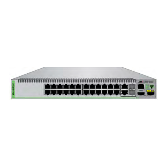
Chapter 1: Overview Front Panels The front panels of the 8100S Series switches with twisted pair ports are shown in Figure 1. AT-8100S/24C AT-8100S/24 AT-8100S/24POE Figure 1. 8100S Series Switches Front Panel Figure 2 identifies the front panel components on the models with twisted pair ports. -
Page 23: 8100S Fiber Optic Series Switches
Stack Installation Guide for 8100S Series Switches 8100S Fiber Optic Series Switches The three fiber optic models in the 8100S Series are listed here: AT-8100S/16F8-SC AT-8100S/16F8-LC AT-8100S/24F-LC Hardware Table 2 lists the hardware features of the fiber optic 8100S Series switches. -
Page 24: Front Panels
Chapter 1: Overview Front Panels The front panels of the fiber optic switches are shown in Figure 3 here and Figure 4 on page 25. AT-8100S/16F8-SC 100Base-FX Fiber 10/100Base-TX Management Twisted Pair Optic Ports with Panel Duplex SC Connectors Ports Combo 10/100/1000Base-T Ports and SFP Slots... -
Page 25: Fiber Optic Ports
Stack Installation Guide for 8100S Series Switches AT-8100S/24-LC 100Base-FX Fiber Management Optic Ports with Panel Duplex LC Connectors Combo 10/100/1000Base-T Ports and SFP Slots Figure 4. Front Panels of the 8100S Fiber Optic Series (Continued) Fiber Optic Ports Table 3 lists the general specifications of the fiber optic ports on the fiber optic switches. -
Page 26: Back Panel Components
Chapter 1: Overview Back Panel Components Figure 5 shows the back panel of the AT-8100S/24C Switch, which has a single power supply. AC Power Connector Figure 5. Back Panels of the Single Power Supply Switches Figure 6 shows the back panels of the dual power supply models. -
Page 27: Management Panel
Stack Installation Guide for 8100S Series Switches Management Panel Figure 7 identifies the components of the management panel. Console Management Port Stack ID eco-friendly Button Stacking Ports Figure 7. Management Panel... -
Page 28: Model Naming Conventions
This is the number of 10/100Base-TX ports. The letters “POE” indicate support for Power over Ethernet. The letter “C” in the AT-8100S/24C model name denotes that the unit, which has just one power supply, is smaller and more compact than the other models. -
Page 29: Table 5: Model Naming Conventions Of The Fiber Optic 8100S Series Switches
Stack Installation Guide for 8100S Series Switches The conventions are defined in Table 5. Table 5. Model Naming Conventions of the Fiber Optic 8100S Series Switches Convention Definition This is the product name. The letter “S” indicates that the model is stackable. This is the number of 100Base-FX fiber optic ports. -
Page 30: 10/100Base-Tx Twisted Pair Ports
Chapter 1: Overview 10/100Base-TX Twisted Pair Ports The switches have 8 or 24 10/100Base-TX ports. Speed The ports can operate at either 10 or 100 Mbps. The speeds may be set manually using the management software or automatically with Auto- Negotiation (IEEE 802.3u), the default setting. -
Page 31: Maximum Distance
Stack Installation Guide for 8100S Series Switches Maximum The ports have a maximum operating distance of 100 meters (328 feet). Distance Power Over The 10/100Base-TX ports on the AT-8100S/24POE Switch supports Power over Ethernet (PoE), which is a standard whereby DC power is Ethernet provided by the switch to network devices over the network twisted pair cables. -
Page 32: 10/100/1000Base-T Twisted Pair Ports
Chapter 1: Overview 10/100/1000Base-T Twisted Pair Ports The switches have two 10/100/1000Base-T ports. These ports are paired with SFP slots to form combo ports. Speed The ports can operate at 10, 100, or 1000 Mbps. The speeds may be set manually using the management software or automatically with Auto- Negotiation (IEEE 802.3u), the default setting. -
Page 33: Maximum Distance
Stack Installation Guide for 8100S Series Switches Maximum The ports have a maximum operating distance of 100 meters (328 feet). Distance Power Over The 10/100/1000Base-T ports on the AT-8100S/24POE Switch does not support PoE. Ethernet Cable The cable requirements of the ports are given in Table 7. Requirements Table 7. -
Page 34: Sfp Slots
The switches support a variety of short and long distance, 100 and 1000 Mbps fiber optic SFP modules. For a list of supported SFP modules, contact your Allied Telesis representative or visit our web site. The two SFP slots are paired with the 10/100/1000Base-T ports to form combo ports. -
Page 35: Power Over Ethernet
Stack Installation Guide for 8100S Series Switches Power Over Ethernet The AT-8100S/24POE Switch features Power over Ethernet (PoE) on the 10/100Base-TX ports. PoE is used to supply power to network devices over the same twisted pair cables that carry the network traffic. The main advantage of PoE is that it can make it easier to install a network. -
Page 36: Power Budget
Chapter 1: Overview Table 9. IEEE Powered Device Classes Maximum Power Power Ranges of the Class Output from a Switch Port 15.4W 0.44W to 12.95W 4.0W 0.44W to 3.84W 7.0W 3.84W to 6.49W 15.4W 6.49W to 12.95W 30.0W 12.95W to 25.5W Power Budget The AT-8100S/24POE Switch has a power budget of 370 watts. -
Page 37: Port Prioritization
Stack Installation Guide for 8100S Series Switches Port If the power requirements of the powered devices exceed the switch’s power budget, the switch will deny power to some ports based on a Prioritization system called port prioritization. You may use this mechanism to ensure that powered devices critical to the operations of your network are given preferential treatment by the switch in the distribution of power should the demands of the devices exceed the available capacity. -
Page 38: Wiring Implementation
Chapter 1: Overview Wiring The IEEE 802.3af standard defines two methods by which a PSE, such as the switch, can transmit DC power over twisted pair cables to PDs. These Implementation methods, known as modes A and B, identify the wire strands the switch should use when sending DC power to a PD. -
Page 39: S1 And S2 Stacking Ports
Stack Installation Guide for 8100S Series Switches S1 and S2 Stacking Ports The switch may be used as a stand-alone unit or as part of a stack in which multiple units are interconnected via the S1 and S2 stacking ports on the front panels. -
Page 40: Eco-Friendly Button
Chapter 1: Overview eco-friendly Button You may turn off the port LEDs to conserve electricity when you are not monitoring the switch. The LEDs may be toggled with the eco-friendly button on the front panel of the switch or the ECOFRIENDLY LED and NO ECOFRIENDLY LED commands in the Global Configuration mode of the command line interface. -
Page 41: Leds
Stack Installation Guide for 8100S Series Switches LEDs Here are the descriptions of the switch’s LEDs. 10/100Base-TX The 10/100Base-TX twisted pair ports have link/activity and duplex mode LEDs. Twisted Pair Port LEDs Link/Activity Duplex Mode Link/Activity Duplex Mode Figure 10. 10/100Base-TX Port LEDs The LEDs are described in this table. -
Page 42: 10/100/1000Base-T Twisted Pair Port Leds
Chapter 1: Overview Here are the LED guidelines: The LEDs do not display port speed. That information may be viewed using the management software. The LEDs on the AT-8100S/24POE Switch do not display PoE information. That information may be viewed using the management software. -
Page 43: 100Base-Fx Port Leds
Stack Installation Guide for 8100S Series Switches Table 11. 10/100/1000Base-T Port LEDs (Continued) State Description Duplex The port is operating in half-duplex mode. Mode Solid green The port is operating in full-duplex mode. 100Base-FX Port Each of the 100Base-FX ports on the AT-8100S/16F8-SC, AT-8100S/ 16F8-LC, and AT-8100S/24F-LC Switches has a single LED, labeled L/A LEDs for Link/Activity. -
Page 44: Sfp Slot Led
Chapter 1: Overview SFP Slot LED Each SFP slot has one LED. SFP Slot LEDs Figure 13. SFP Slot LEDs The SFP slot LED is described in Table 13. Table 13. SFP Slot LED State Description Link/Activity The SFP slot is empty or the SFP module has not established a link to a network device. -
Page 45: S1 And S2 Stack Ports Leds
Stack Installation Guide for 8100S Series Switches S1 and S2 Stack Each stacking port has one link/activity LED labelled LINK/ACT. Ports LEDs Stacking Port LEDs Figure 14. Stacking Port S1 and S2 LEDs The stacking port LED is described in Table 14. Table 14. -
Page 46: Stack Id Led
Chapter 1: Overview Stack ID LED The Stack ID LED displays the ID number of the switch. A stand-alone switch should have the ID number 0. Switches connected with the stacking ports to form a virtual stack must have unique numbers. Chapter 5, “Assigning the Stack ID Numbers and Cabling the Stacking Ports”... -
Page 47: Console Port
Stack Installation Guide for 8100S Series Switches Console Port The Console port is used to configure the features and parameter settings of the switch. This type of management uses serial RS-232 and is commonly referred to as local or out-of-band management because it is not conducted over your network. -
Page 48: Power Supplies
Chapter 1: Overview Power Supplies The switches are powered by two internal AC power supplies, except for the AT-8100S/24C Switch, which has one power supply. The supplies are not field-replaceable and each has a separate AC connector on the back panels. -
Page 49: Power Connectors
Power Connectors The 8100S Series switches have two AC or DC power supply sockets on the back panels, except for the AT-8100S/24C Switch, which has just one AC power supply socket. AC switches are powered on or off by connecting or disconnecting the power cords. - Page 50 Chapter 1: Overview...
-
Page 51: Chapter 2: Stacking Overview
Chapter 2 Stacking Overview This chapter contains the following sections: “Stacking Guidelines” on page 52 “Master Switch” on page 54 “Stacking Port Topologies” on page 55 “Active Boot Configuration File” on page 57 “Initialization Process” on page 59... -
Page 52: Stacking Guidelines
A stack can have up to eight switches or 208 ports. The switches of a stack may be the same model or different models. For instance, a stack can have AT-8100S/24C, AT-8100S/ 24, and AT-8100S/16F8-SC Switches. Stacking is not supported on the 8100L Series switches. - Page 53 Stack Installation Guide for 8100S Series Switches The other units are referred to as member switches. The stacking feature described in this guide is unrelated to the enhanced stacking feature described in the AT-8100 Series AlliedWare Plus Command Line Interface User’s Guide. They are completely different features.
-
Page 54: Master Switch
Chapter 2: Stacking Overview Master Switch A stack must have a master switch to coordinate and monitor stack operations. It verifies that the switches are using the same version of management software, that no two switches have the same ID number, and that the stacking ports are cabled correctly. -
Page 55: Stacking Port Topologies
Stack Installation Guide for 8100S Series Switches Stacking Port Topologies The switches are connected together with the S1 and S2 ports in the management panels, and the stacking cables that come with the units. There are two wiring configurations. The first topology is called the duplex- chain topology. -
Page 56: Figure 16 Duplex-Chain And Duplex-Ring Configurations
Chapter 2: Stacking Overview Duplex-chain Configuration Duplex-ring Configuration Figure 16 Duplex-chain and Duplex-ring Configurations... -
Page 57: Active Boot Configuration File
Stack Installation Guide for 8100S Series Switches Active Boot Configuration File The master switch stores the settings of the entire stack in a file in its file system. This file is referred to as the active boot configuration file. The switch updates the file with the most recent parameter changes whenever you issue the WRITE or COPY RUNNING-CONFIG STARTUP-CONFIG command. - Page 58 Chapter 2: Stacking Overview instructs the other switches to designate that filename as the active boot configuration file so that they use that file if they become the master switch. Here is an example of how the process works. Let’s assume your stack has three switches, assigned the ID numbers 1 to 3.
-
Page 59: Initialization Process
Stack Installation Guide for 8100S Series Switches Initialization Process The switches of the stack synchronize their operations in a five phase process when they are powered on or reset, and prior to forwarding network traffic from their ports. In the first three phases the switches initialize their management software and features. - Page 60 Chapter 2: Stacking Overview...
-
Page 61: Chapter 3: Beginning The Installation
Chapter 3 Beginning the Installation The chapter contains the following sections: “Installation Overview” on page 62 “Reviewing Safety Precautions” on page 63 “Planning the Installation” on page 67 “Unpacking the Switch” on page 69... -
Page 62: Installation Overview
Chapter 3: Beginning the Installation Installation Overview Table 15 lists the installation procedures for a stack of 8100S Series switches. The procedures should be performed in the order presented in the table. Table 15. Installation Procedures Step Procedure “Reviewing Safety Precautions” on page 63 “Planning the Installation”... -
Page 63: Reviewing Safety Precautions
Note The indicates that a translation of the safety statement is available in a PDF document titled “Translated Safety Statements” posted on the Allied Telesis website at www.alliedtelesis.com. Warning Class 1 Laser product. L1 Warning Do not stare into the laser beam. L2... - Page 64 Chapter 3: Beginning the Installation Warning Class I Equipment. This equipment must be earthed. The power plug must be connected to a properly wired earth ground socket outlet. An improperly wired socket outlet could place hazardous voltages on accessible metal parts. E4 Note Pluggable Equipment.
- Page 65 Stack Installation Guide for 8100S Series Switches Caution Risk of explosion if battery is replaced by an incorrect type. Replace only with the same or equivalent type recommended by the manufacturer. Dispose of used batteries according to the manufacturer’s instructions. Attention: Le remplacement de la batterie par une batterie de type incorrect peut provoquer un danger d’explosion.
- Page 66 Chapter 3: Beginning the Installation Warning Reliable earthing of rack-mounted equipment should be maintained. Particular attention should be given to supply connections other than direct connections to the branch circuits (e.g., use of power strips). E37 Warning To reduce the risk of electric shock, the PoE ports on this product must not connect to cabling that is routed outside the building where this device is located.
-
Page 67: Planning The Installation
Warning The switches of a stack should only be installed in a standard 19- inch equipment rack. Allied Telesis does not recommend placing switches on top of one another on a table or desktop because that could present a personal safety hazard if you need to move or replace switches. -
Page 68: Choosing A Site
Chapter 3: Beginning the Installation To count the ports on the twisted pair models, include the two 10/100/ 1000Base-T ports along with the 10/100Base-TX ports, but not the SFP slots. For example, a stack of AT-8100S/24 Switches could have up to eight units: 8 switches x 26 ports = 208 ports To count the ports on the fiber optic models, include the fiber optic, 10/... -
Page 69: Unpacking The Switch
If any items are missing or damaged, contact your Allied Telesis sales representative for assistance. 8100S Series The 8100S Series switches, except the AT-8100S/24C Switch, come with the components listed in Figure 19. Switches One 8100S Series switch One 2 m (6.6 ft) local management cable with... -
Page 70: At-8100S/24C Switch
Chapter 3: Beginning the Installation AT-8100S/24C The AT-8100S/24C Switch comes with the items listed in Figure 20. Switch One AT-8100S/24C Switch One 2 m (6.6 ft) local management cable with RJ-45 (8P8C) and DB-9 (D-sub 9-pin) connectors. One 1 m (3.3 ft) stacking cable with two type A HDMI connectors. -
Page 71: Chapter 4: Installing And Labeling The Switches In An Equipment Rack
Chapter 4 Installing and Labeling the Switches in an Equipment Rack Here are the procedures in this chapter: “Installing the Switches in an Equipment Rack” on page 72 “Labeling the Switches” on page 77... -
Page 72: Installing The Switches In An Equipment Rack
Four standard equipment rack screws (not provided) Perform this procedure to install the switch in a 19-inch equipment rack, Caution The chassis may be heavy and awkward to lift. Allied Telesis recommends that you get assistance when mounting the chassis in an equipment rack. E28 1. -
Page 73: Figure 23: Attaching The Brackets To Install The Switch In An Equipment Rack
Stack Installation Guide for 8100S Series Switches 4. For all switches except the AT-8100S/24C Switch, secure the two rack mount brackets to the sides of the switch using the eight bracket screws included with the unit. Figure 23 here and Figure 24 on page 74 illustrate the four possible bracket positions. -
Page 74: Figure 24: Attaching The Brackets To Install The Switch In An Equipment Rack (Continued)
8100S Series switches in the equipment rack. The possible positions of the brackets are shown in Figure 25 here and Figure 26 on page 75. Figure 25. Attaching the Brackets to the AT-8100S/24C Switch to Install the Switch in an Equipment Rack... -
Page 75: Figure 26: Attaching The Brackets To The At-8100S/24C Switch To Install The Switch In An Equipment Rack (Continued)
Stack Installation Guide for 8100S Series Switches Figure 26. Attaching the Brackets to the AT-8100S/24C Switch to Install the Switch in an Equipment Rack (Continued) -
Page 76: Figure 27: Mounting The Switch In An Equipment Rack
Chapter 4: Installing and Labeling the Switches in an Equipment Rack 5. Have another person hold the switch in the equipment rack while you secure it using standard screws (not provided). Figure 27. Mounting the Switch in an Equipment Rack Repeat this procedure to install all of the switches in the equipment rack. -
Page 77: Labeling The Switches
Stack Installation Guide for 8100S Series Switches Labeling the Switches Starting with the top or bottom switch of the stack, assign each unit a number starting with 1 and affix labels with the numbers to their front panels or adjacent to the units on the equipment rack. The numbers will be their stack ID numbers, which you’ll assign in Chapter 5, “Assigning the Stack ID Numbers and Cabling the Stacking Ports”... - Page 78 Chapter 4: Installing and Labeling the Switches in an Equipment Rack...
-
Page 79: Chapter 5: Assigning The Stack Id Numbers And Cabling The Stacking Ports
Chapter 5 Assigning the Stack ID Numbers and Cabling the Stacking Ports The procedures in this chapter explain how to configure the stack ID numbers on the switches and cable the S1 and S2 stacking ports: “Powering on a Switch” on page 80 ... -
Page 80: Powering On A Switch
Chapter 5: Assigning the Stack ID Numbers and Cabling the Stacking Ports Powering on a Switch Power on one of the switches in the stack with these instructions. 1. Plug the power cord into the AC power connector on the back panel of the unit (see Figure 29). - Page 81 Stack Installation Guide for 8100S Series Switches 2. Connect the other end of the power cord to an appropriate AC power outlet. For power specifications for the switch, refer to “Power Specifications” on page 133. 3. Wait one minute for the switch to initialize its management software and then go to “Verifying and Setting the Stack ID Numbers”...
-
Page 82: Verifying And Setting The Stack Id Numbers
Chapter 5: Assigning the Stack ID Numbers and Cabling the Stacking Ports Verifying and Setting the Stack ID Numbers After the switch has initialized its management software, examine the number displayed on the Stack ID LED to see if it matches the number you want it to have in the stack. -
Page 83: Starting A Telnet Management Session
Stack Installation Guide for 8100S Series Switches Figure 30. Connecting the Management Cable to the RJ-45 Terminal Port on the Switch 2. Connect the other end of the cable to an RS-232 port on a terminal or a personal computer with a terminal emulation program. 3. -
Page 84: Figure 31: Connecting The Twisted Pair Cable To A Networking Port On The Switch
Chapter 5: Assigning the Stack ID Numbers and Cabling the Stacking Ports Note Your computer automatically defaults to an 169.254.n.n address if it is running a DHCP client and does not receive a response from a DHCP server. To have a DHCP client assign the address, disconnect your computer from your network, power it on, wait for the DHCP client to generate the IP address 169.254.n.n, and then connect the computer to your new 8100S Series switch. -
Page 85: Changing The Stack Id Number
Stack Installation Guide for 8100S Series Switches Changing the To set the stack ID number: Stack ID Number 1. When prompted, enter a user name and password to log on the switch. If this is the initial management session of the switch, enter “manager” as the user name “friend”... - Page 86 Chapter 5: Assigning the Stack ID Numbers and Cabling the Stacking Ports 4. Type Y to change the switch’s ID number and reset the unit, or N to cancel the procedure. 5. Wait for the switch to initialize its management software and afterwards examine the Stack ID LED again to confirm that it’s displaying the correct stack ID number for the switch.
-
Page 87: Cabling The Stacking Ports
Stack Installation Guide for 8100S Series Switches Cabling the Stacking Ports Now that you’ve assigned and verified the stack ID numbers of the switches, you may connect the stacking cables to the S1 and S2 stacking ports on the front panels of the units. A stacking cable must crossover to different stacking ports on two switches, such that it connects the S1 port on one switch to the S2 port one another switch. -
Page 88: Figure 35: Example Stack Of Four Switches
Chapter 5: Assigning the Stack ID Numbers and Cabling the Stacking Ports An example of a stack of four switches is shown in this figure. Figure 35. Example Stack of Four Switches... -
Page 89: Figure 36: Example Stack Of Four Switches With A Redundant Path
Stack Installation Guide for 8100S Series Switches 4. To add a redundant path to the stack, connect a stacking cable to the empty stacking ports on the top and bottom switches. An example of a stack with a redundant path is shown in Figure 36. Figure 36. - Page 90 Chapter 5: Assigning the Stack ID Numbers and Cabling the Stacking Ports...
-
Page 91: Chapter 6: Powering On And Verifying The Stack
Chapter 6 Powering On and Verifying the Stack The procedures in this chapter are listed here: “Powering on AC Switches” on page 92 “Powering On DC Switches” on page 97 “Verifying the Installation” on page 101... -
Page 92: Powering On Ac Switches
All of the models have two power supplies with separate connectors. The only exception is the AT-8100S/24C Switch, which has only one power supply. Figure 37. Plugging in the AC Power Cords Consider the following items as you power on the stack: ... -
Page 93: Monitoring The Initialization Processes
Stack Installation Guide for 8100S Series Switches Warning Power cord is used as a disconnection device. To de-energize equipment, disconnect the power cord. E3 Note Pluggable Equipment. The socket outlet shall be installed near the equipment and shall be easily accessible. E5 Monitoring the It takes a minimum of three minutes for the switches of the stack to initialize their management software programs and features, perform the... -
Page 94: Figure 38: Switch Initialization Messages
Chapter 6: Powering On and Verifying the Stack You may also monitor the processes by connecting a terminal or computer with has a terminal emulator program to the Console port on the master switch. The messages in Figure 38 here, Figure 39 on page 95, and Figure 40 on page 96 are displayed during the initialization process. -
Page 95: Figure 39: Switch Initialization Messages (Continued)
Stack Installation Guide for 8100S Series Switches Initializing Port Statistics ......done! Initializing Snmp Service ......done! Initializing Web Service ......done! Initializing Monitor ........ done! Initializing STP ........done! Initializing SPANNING TREE ......done! Initializing L2_MGMT ........ done! Initializing LLDP_RX ........ done! Initializing LLDP_TX ........ -
Page 96: Figure 40: Switch Initialization Messages (Continued)
Chapter 6: Powering On and Verifying the Stack Stack topology discovery is in process... Please Wait Loading configuration file “boot.cfg” ..done! Sending Configuration file to all slaves. Please wait... 00000001 Sending configuration file done! Press <ENTER> key to connect... New Switch 2 (00:15:77:99:99:91) is added into stack Figure 40. -
Page 97: Powering On Dc Switches
The AT-8100S/24 Switch is currently the only model with a DC power supply option. For details on the availability of other DC models, contact your Allied Telesis representative. 1. Power off the DC circuit to which the switch will be connected. -
Page 98: Figure 41: Dc Terminal Block
Chapter 6: Powering On and Verifying the Stack Positive Ground Negative Terminal Terminal Terminal Figure 41. DC Terminal Block 3. With a 14-gauge wire-stripping tool, strip the three wires in the tray cable coming from the DC input power source to 8mm ± 1mm (0.31 in., ±... -
Page 99: Figure 43: Inserting Wires Into The Dc Terminal Block
Stack Installation Guide for 8100S Series Switches Figure 43. Inserting Wires into the DC Terminal Block 5. Connect the positive feed wire to the terminal block marked + (plus). 6. Connect the negative feed wire to the terminal block marked - (minus). Warning Check to see if there are any exposed copper strands coming from the installed wires. - Page 100 Chapter 6: Powering On and Verifying the Stack 11. Repeat this procedure to power on the second power supply. Warning This unit might have more than one power source. To reduce the risk of electric shock, disconnect all power cords before servicing the unit.
-
Page 101: Verifying The Installation
AT-8100S/24 00:00:54:55:56:c4 2.2.2 AT-8100S/24POE 00:00:54:55:56:30 2.2.2 AT-8100S/24C 00:00:54:55:56:92 2.2.2 AT-8100S/24POE Figure 44. SHOW STACK Command 3. Match the entries in the table with the switches in the equipment rack by referring to the labels on the front panels of the units. The ID number and MAC address on a switch’s label should match the unit’s... - Page 102 Chapter 6: Powering On and Verifying the Stack Examine the stack ID LEDs to verify that each switch has been assigned a unique ID number, in the range of 1 to 8. If there are switches with duplicate numbers, power off the stack and perform the procedures in Chapter 5, “Assigning the Stack ID Numbers and Cabling the Stacking Ports”...
-
Page 103: Chapter 7: Cabling The Network Ports
Chapter 7 Cabling the Network Ports This chapter contains the following procedures: “Cabling the Twisted Pair and Fiber Optic Ports” on page 104 “Installing Optional SFP Transceivers” on page 106 “Managing the Stack” on page 110... -
Page 104: Cabling The Twisted Pair And Fiber Optic Ports
Chapter 7: Cabling the Network Ports Cabling the Twisted Pair and Fiber Optic Ports This section contains the guidelines to cabling the twisted pair and fiber optic ports. Twisted Pair Here are the guidelines to cabling the 10/100Base-TX and 10/100/ 1000Base-T twisted pair ports: Ports ... -
Page 105: Fiber Optic Ports
Stack Installation Guide for 8100S Series Switches The 10/100/1000Base-T ports must be set to Auto-Negotiation, the default setting, to operate at 1000Mbps. The default duplex mode setting for the ports is Auto-Negotiation. This setting is appropriate for ports connected to network devices that also support Auto-Negotiation for duplex modes. -
Page 106: Installing Optional Sfp Transceivers
Chapter 7: Cabling the Network Ports Installing Optional SFP Transceivers Review the following guidelines before installing optional SFP transceivers in the switch: The SFP slots are part of combo ports, with 10/100/1000Base-T ports. For operational information, refer to “SFP Slots” on page 34. ... -
Page 107: Figure 45: Removing The Dust Plug From An Sfp Slot
3. If you are installing the transceiver in the top SFP slot, position the transceiver with the Allied Telesis label facing up. If you are installing the transceiver in the bottom slot, position the transceiver with the label facing down. -
Page 108: Figure 47: Removing The Dust Cover From The Sfp Module
Chapter 7: Cabling the Network Ports Figure 47. Removing the Dust Cover from the SFP Module 6. Verify that the handle on the SFP transceiver is in the upright position, as shown in Figure 48. SFP Handle Figure 48. Positioning the SFP Handle in the Upright Position... -
Page 109: Figure 49: Connecting The Fiber Optic Cable To The Sfp Module
Stack Installation Guide for 8100S Series Switches 7. Connect the fiber optic cable to the SFP module, as shown in Figure 49. Figure 49. Connecting the Fiber Optic Cable to the SFP Module 8. Repeat this procedure if you have other SFP transceivers to install. -
Page 110: Managing The Stack
Chapter 7: Cabling the Network Ports Managing the Stack You may manage an 8100S Series stack with these methods and tools: Local management Telnet client Secure shell client Web browser SNMPv1, v2C, v3 Local You may manage a stack through the Console port on the master switch. This is called local management or out-of-band management because the Management management sessions are not conducted over your network. -
Page 111: Secure Shell Management
Stack Installation Guide for 8100S Series Switches address 169.254.1.1. Refer to your computer’s documentation for instructions on how to set the IP address. Note Your computer automatically defaults to an 169.254.n.n address if it is running a DHCP client and does not receive a response from a DHCP server. -
Page 112: Web Browser Management
Chapter 7: Cabling the Network Ports Web Browser Yet another way to remotely manage a stack is with a web browser. A special web browser interface, featuring both non-secure (HTTP) and Management secure (HTTPS) operation, lets you monitor and configure many of the switch’s features from a series of windows. - Page 113 Stack Installation Guide for 8100S Series Switches The slot ID value, which is used to specify slot numbers in a multi-module chassis, does not apply to 8100S Series switches and should always be 0. The third value is a port number on the switch. You may specify one port number in a PORT parameter, but you may specify more than one PORT parameter in many of the commands that support the parameter.
- Page 114 Chapter 7: Cabling the Network Ports...
-
Page 115: Chapter 8: Troubleshooting
Note For further assistance, please contact Allied Telesis Technical Support. Refer to “Contacting Allied Telesis” on page 15. Problem 1: The Stack ID LED on the front of the switch is off. Solutions: The unit is not receiving power. Try the following: ... - Page 116 Chapter 8: Troubleshooting Problem 3: The stack ID LEDs on the switches of the stack are flashing the ID numbers and the letter “H” every few seconds. Solution: This is normal for the LEDs when the switches are operating in a stack configuration.
- Page 117 Stack Installation Guide for 8100S Series Switches Check that the SFP module is fully inserted in the slot. Verify that the operating specifications of the fiber optic ports on the SFP transceiver and the remote network device are compatible.
- Page 118 Chapter 8: Troubleshooting...
-
Page 119: Chapter 9: Adding Or Removing Switches
Chapter 9 Adding or Removing Switches The procedures in this chapter explain how to add or remove switches from the stack. The chapter contains the following sections: “Removing or Replacing the Master Switch” on page 120 “Adding a New Member Switch” on page 128 ... -
Page 120: Removing Or Replacing The Master Switch
Chapter 9: Adding or Removing Switches Removing or Replacing the Master Switch This procedure is divided into the following phases: Phase 1: “Uploading the Active Configuration File” on page 121 Phase 2: “Removing the Current Master Switch” on page 122 ... -
Page 121: Uploading The Active Configuration File
Stack Installation Guide for 8100S Series Switches Uploading the The first step to replacing the master switch of the stack is to upload the active boot configuration file, which contains the configuration settings of Active the stack, to your workstation or, alternatively, to a TFTP server. You’ll Configuration download the file to the new switch later in these procedures. -
Page 122: Removing The Current Master Switch
Chapter 9: Adding or Removing Switches sure to include the .CFG extension. This example of the command uploads a configuration file called stack_eng.cfg: awplus# copy stack_eng.cfg zmodem 4. After you enter the command, begin the file transfer using your terminal emulator program. The upload, which takes only a few seconds, is completed when the command prompt is displayed again. -
Page 123: Figure 53: Removing The Fiber Optic Cable From The Sfp Module
Stack Installation Guide for 8100S Series Switches Note If the switch has SFP modules, perform steps 3 to 7. Otherwise, go to step 8. 3. Label and remove the fiber optic cable from the SFP module. Figure 53. Removing the Fiber Optic Cable from the SFP Module 4. -
Page 124: Figure 55: Removing The Sfp Module
Chapter 9: Adding or Removing Switches 5. Remove and label the module from the switch, as shown in Figure 55. Figure 55. Removing the SFP Module 6. Install the dust cover in the SFP slot, as shown in Figure 56. Figure 56. -
Page 125: Configuring The New Master Switch
Stack Installation Guide for 8100S Series Switches Figure 57. Removing the Stacking Cables 9. Remove the switch from the equipment rack. 10. Go to the next procedure. Configuring the With the master switch removed from the equipment rack, you are ready to install the new master switch by configuring its stack ID number and New Master downloading the configuration file. - Page 126 Chapter 9: Adding or Removing Switches 5. Assign the switch its stack ID number. For instructions, refer to “Changing the Stack ID Number” on page 85. 6. After configuring the stack ID number, reestablish your local management session. 7. Download onto the switch the configuration file you uploaded earlier from the previous master switch or from one of the member switches.
-
Page 127: Connecting The New Master Switch To The Stack
Stack Installation Guide for 8100S Series Switches 11. Use the EXIT command to return to the Privileged Exec mode and Issue the SHOW CONFIG command to verify that the downloaded configuration file is the new active configuration file. The “Current boot config”... -
Page 128: Adding A New Member Switch
Chapter 9: Adding or Removing Switches Adding a New Member Switch Here are the guidelines to adding a new member switch to a stack: You have to power off a stack to add new member switches. To minimize the disruption to network users, you should add new switches to a stack during non-business hours. - Page 129 Stack Installation Guide for 8100S Series Switches c. If the “Current boot config” field is displaying the filename BOOT.CFG, perform this command to create an archive copy of it. Otherwise, go to step 2. awplus# copy boot.cfg archive_boot.cfg d. Log off by entering the EXIT command. 2.
-
Page 130: Removing A Member Switch
Chapter 9: Adding or Removing Switches Removing a Member Switch Here are the guidelines to removing a member switch from the stack: You may leave the stack powered on if it is cabled in the duplex- ring topology, or if it is cabled in the duplex-chain topology and the switch to be removed is located at the end of the stack. -
Page 131: Appendix A: Technical Specifications
8100L and 8100S Series Switches. Physical Specifications Dimensions (H x W x D) Table 17. Product Dimensions AT-8100S/24C 4.4 cm x 33.0 cm x 20.3 cm (1.7 in. x 13.0 in. x 8.1 in.) AT-8100S/24 4.4 cm x 44.1 cm x 29.1 cm AT-8100S/24F-LC (1.7 in. -
Page 132: Environmental Specifications
Appendix A: Technical Specifications Weights Table 18. Product Weights AT-8100S/24C 2.2 kg (4.8 lb.) AT-8100S/24 3.6 kg (8.0 lb.) AT-8100S/24POE 5.0 kg (11.0 lb.) AT-8100S/16F8-SC 4.1 kg (9.1 lb.) AT-8100S/16F8-LC 4.4 kg (9.75 lb.) AT-8100S/24F-LC 4.4 kg (9.75 lb.) Ventilation Table 19. -
Page 133: Power Specifications
Stack Installation Guide for 8100S Series Switches Power Specifications Maximum Power Consumptions Table 21. Maximum Power Consumptions AT-8100S/24C 18.3 watts AT-8100S/24 19.5 watts AT-8100S/24POE 459.3 watts AT-8100S/16F8-SC 22 watts AT-8100S/16F8-LC 22 watts AT-8100S/24F-LC 22 watts Input Voltages Table 22. Input Voltages AT-8100S/24C AC model: 100-240 VAC, 1.0 A... -
Page 134: Certifications
Appendix A: Technical Specifications Certifications Table 23. Product Certifications EMI (Emissions) FCC Class A, EN55022 Class A, EN61000-3-2, EN61000-3-3, VCCI Class A, CISPR Class A, C-TICK, EMC (Immunity) EN55024 Electrical and Laser Safety EN60950-1 (TUV), UL 60950-1 ), EN60825 Compliance Marks , TUV, C-Tick RJ-45 Twisted Pair Port Pinouts Figure 58 illustrates the pin layout of an RJ-45 connector and port. -
Page 135: Table 25: Pin Signals - 1000 Mbps
Stack Installation Guide for 8100S Series Switches Table 25 lists the pin signals when a port operating at 1000 Mbps. Table 25. Pin Signals - 1000 Mbps Pinout Pair Pair 1 + Pair 1 - Pair 2 + Pair 3 + Pair 3 - Pair 2 - Pair 4 +... -
Page 136: Fiber Optic Port Specifications
Appendix A: Technical Specifications Fiber Optic Port Specifications Table 26 lists the specifications of the 100Base-FX fiber optic ports on the AT-8100S/16F8-SC Switch. Table 26. Fiber Optic Port Specifications for the AT-8100S/16F8-SC Switch General Maximum Distance 2 km Fiber Optic Cable 50/125 or 62.5/125 µm (core/ cladding) multimode fiber optic cable... -
Page 137: Table 27: Fiber Optic Port Specifications For The At-8100S/16F8-Lc And At-8100S/24F-Lc Switches
Stack Installation Guide for 8100S Series Switches Table 27 lists the specifications of the 100Base-FX fiber optic ports on the AT-8100S/16F8-LC and AT-8100S/24F-LC Switches. Table 27. Fiber Optic Port Specifications for the AT-8100S/16F8-LC and AT-8100S/24F-LC Switches General Maximum Distance 2 km Fiber Optic Cable 50/125 or 62.5/125 µm (core/ cladding) multimode fiber optic... -
Page 138: Style Serial Console Port Pinouts
Appendix A: Technical Specifications RJ-45 Style Serial Console Port Pinouts Table 28 lists the pin signals of the RJ-45 style serial Console port. Table 28. RJ-45 Style Serial Console Port Pin Signals Signal Looped to pin 8. Looped to pin 7. Transmit Data Ground Ground... -
Page 139: Stacking Port Pinouts
Stack Installation Guide for 8100S Series Switches Stacking Port Pinouts Figure 59 illustrates the pin layout of the S1 and S2 stacking ports. Figure 59. Stacking Port Pin Layout (Front View) Table 29 lists the pin signals for the stacking ports. Table 29. - Page 140 Appendix A: Technical Specifications...
Need help?
Do you have a question about the AT-8100S/24C and is the answer not in the manual?
Questions and answers