Table of Contents
Advertisement
Advertisement
Table of Contents

Related Manuals for Allied Telesis AT-8350GB


Summary of Contents for Allied Telesis AT-8350GB
- Page 1 Fast Ethernet ® Switch AT-8350GB Installation Guide PN 613-50307-00 Rev B...
- Page 2 Copyright 2002 Allied Telesyn, Inc. 960 Stewart Drive Suite B, Sunnyvale, CA 94085 USA All rights reserved. No part of this publication may be reproduced without prior written permission from Allied Telesyn, Inc. All other product names, company names, logos or other designations mentioned herein are trademarks or registered trademarks of their respective owners.
- Page 3 Electrical Safety and Emission Statement Standards: This product meets the following standards. U.S. Federal Communications Commission RADIATED ENERGY Note: This equipment has been tested and found to comply with the limits for a Class A digital device pursuant to Part 15 of the FCC Rules.
-
Page 5: Table Of Contents
Table of Contents Preface ............................................9 How This Guide is Organized ..................................... 9 Document Conventions ....................................10 Where to Find Web-based Guides .................................11 Contacting Allied Telesyn Technical Support ............................12 Online Support......................................12 Telephone Support..................................... 12 Management Software Updates ..................................13 For Sales or Corporate Information ................................14 Chapter 1 Product Description ......................................15 Summary of Features ......................................15... - Page 6 Table of Contents Duplex Mode........................................ 46 Store and Forward...................................... 46 Backpressure and Flow Control................................46 Network Topologies ......................................48 Power Workgroup Topology .................................. 48 Collapsed Backbone - Hub Topology..............................49 Switch Stacking Topology ..................................50 Chapter 2 Installation ........................................... 51 Installation Safety Precautions ..................................
- Page 7 List of Figures Figure 1: AT-8350GB Front Panel ...................................16 Figure 2: AT-8350GB Back Panel ..................................16 Figure 3: Twisted Pair Ports ....................................17 Figure 4: RJ-45 Connector and Port Pin Layout ............................19 Figure 5: GBIC Slots ......................................21 Figure 6: Example of a GBIC Module ................................21 Figure 7: Stacking Ports .....................................22...
- Page 8 List of Figures Figure 38: A Stack of Four Switches ................................66 Figure 39: Connecting the Twisted Pair Data Cables ..........................67 Figure 40: Removing the Dust Cover from a GBIC Module ........................68 Figure 41: Attaching a Fiber Optic Cable to a GBIC Module ........................ 69 Figure 42: FAULT LED ......................................
-
Page 9: Preface
Preface This guide contains instructions on how to install the stackable AT-8350GB Fast Ethernet switch. How This Guide is Organized This manual contains the following chapters and appendices: Chapter 1, Hardware Description, describes the features and components of the switch. -
Page 10: Document Conventions
Preface Document Conventions This document uses the following conventions to highlight important information. Note Notes provide additional information. Warning Warnings inform you that performing or omitting a specific action may result in bodily injury. Caution Cautions inform you that performing or omitting a specific action may result in equipment damage or loss of data. -
Page 11: Where To Find Web-Based Guides
AT-8350GB Installation Guide Where to Find Web-based Guides The Allied Telesyn web site at www.alliedtelesyn.com contains PDF files of the Installation and User Guides for all Allied Telesyn products. The documents can be viewed on-line or downloaded onto a local workstation or server. -
Page 12: Contacting Allied Telesyn Technical Support
Preface Contacting Allied Telesyn Technical Support You can contact Allied Telesyn technical support online or by telephone. Online Support You can request technical support online by accessing the Knowledge Base from our web site at http://kb.alliedtelesyn.com. You can use the Knowledge Base to submit questions to our technical support staff and review answers to previously asked questions. -
Page 13: Management Software Updates
AT-8350GB Installation Guide Management Software Updates Allied Telesyn periodically updates the management software programs for our managed products. You can download new versions of our management software from our web site at www.alliedtelesyn.com our FTP server at ftp.alliedtelesyn.com. To use the FTP server, enter ‘anonymous’... -
Page 14: For Sales Or Corporate Information
Preface For Sales or Corporate Information You can contact Allied Telesyn for sales or corporate information at the location listed below: Allied Telesyn, Inc. 19800 North Creek Parkway, Suite 200 Bothell, WA 98011 Tel: 1 (425) 487-8880 Fax: 1 (425) 489-9191... -
Page 15: Product Description
Chapter 1 Product Description The AT-8350GB is a stackable Layer 2 Fast Ethernet switch. It offers a wide range of features and capabilities, all designed to simplify the task of creating and maintaining a Fast Ethernet network. Summary of Features ❑... -
Page 16: Location Of Components
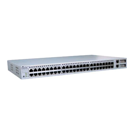
Product Description Location of Components Figure 1 illustrates the front panel of the AT-8350GB Fast Ethernet Switch. Slots GBIC Port LEDs LINK FULL FAULT MODE 10/100Base-TX Ports 10/100/1000Base-T Ports System LEDs Figure 1 AT-8350GB Front Panel Figure 2 illustrates the back panel. -
Page 17: Hardware Features
10/100/1000Base-T Ports 10/100Base-TX Ports Figure 3 Twisted Pair Ports The AT-8350GB Fast Ethernet switch features 48 10/100 Mbps twisted pair ports and two 10/100/1000 Mbps twisted pair ports. The features of the twisted pair ports are described below. Type of Connector All of the twisted pair ports feature 8-pin RJ-45 connectors. - Page 18 Product Description Speed The 10/100Base-TX ports are capable of 10 megabits per second (Mbps) or 100 Mbps speeds. The 10/100/1000Base-TX ports are capable of 10 Mbps, 100 Mbps, or 1000 Mbps speeds. You can set the port speed manually or, since the ports are IEEE 802.3u Auto-Negotiation compliant, you can allow the switch to set each port’s speed automatically.
-
Page 19: Figure 4 Rj-45 Connector And Port Pin Layout
AT-8350GB Installation Guide Duplex Mode Each twisted pair port on the switch can operate in either half- or full- duplex mode. The twisted pair ports are IEEE 802.3u-compliant and will Auto-Negotiate the duplex mode setting. If the end node connected to a twisted pair port on the switch is capable of full-duplex operation, the switch sets the port to full-duplex. - Page 20 Product Description Table 2 lists the RJ-45 port pin signals when a twisted pair port is operating in the MDI-X configuration. Table 2 MDI-X Pin Signals (10/100 Mbps) Signal Table 3 lists the RJ-45 connector pins and their signals when a 10/100/1000 Mbps twisted pair port is operating at 1000 Mbps.
-
Page 21: Gigabit Interface Converter Slots
Interface Converter Slots Figure 5 GBIC Slots The AT-8350GB Fast Ethernet switch has two GBIC slots on the front panel, which correspond to ports 49 and 50. Each slot can accommodate one optional GBIC module. A GBIC module is a gigabit (1000Base) transceiver. GBIC modules can be... -
Page 22: Stacking Ports
Figure 7 Stacking Ports There are two stacking ports on the back of the switch (Figure 7). The ports are used to connect AT-8350GB switches to form a logical switch. A logical switch consists of two or more individual switches that function as one unit. -
Page 23: Expansion Slot
Contact your Allied Telesyn sales representative for a list of available expansion modules for the AT-8350GB switch. For instructions on how to install an expansion module, refer to Installing an Expansion Module on page 62. -
Page 24: System Leds
Product Description System LEDs AT-8350GB Fast Ethernet Switch LINK FULL FAULT System LEDs MODE Figure 9 System LEDs The system LEDs on the left side of front panel display general status information about the entire switch. The system LEDs are defined in Table 4. -
Page 25: 10/100 Mbps Port Leds
AT-8350GB Installation Guide 10/100 Mbps Each 10/100 Mbps port has one LED. Each LED can display a variety of port status information, including link status, speed, and duplex mode. Port LEDs Port 1 Port 2 Port 3 Port No. Figure 10 Port LEDs You use the Mode select button to toggle the port LEDs to display the different information. - Page 26 Product Description Table 5 describes the 10/100Base-T port LEDs. Table 5 10/100 Mbps Port LEDs State Description LINK Flashing Green A link with activity. Steady Green A link with no activity. No link has been established. Green A 100 Mbps link has been established. A 10 Mbps link has been established.
-
Page 27: Gigabit Connector Leds
AT-8350GB Installation Guide Gigabit Connector LEDs Connector LEDs Figure 12 Gigabit Connector LEDs Ports 49 and 50 each have two LEDs. The S (Selection) LED indicates which port, the twisted pair port or a GBIC port, has been activated in the management software. -
Page 28: Expansion Module Leds
Expansion The expansion module has an LED for each port. Use the Mode select button located on the front panel of the AT-8350GB switch to toggle the Module port LEDs to display port status. The LEDs can display a variety of LEDs information, including link status, speed, and duplex mode. -
Page 29: Terminal Port
Note You are not required to manage an AT-8350GB Fast Ethernet switch. The default switch settings may be sufficient for your network, in which case you can use the unit as an unmanaged switch. -
Page 30: Ac Power Connector
Product Description AC Power Connector 100-240 VAC AC power connector Figure 15 AC Power Connector The switch has a single AC power supply socket on the back panel, which has autoswitch AC inputs. Refer to the Technical Specifications on page 89 for the input voltage range. To power ON or OFF the switch, you connect or disconnect the power cord. -
Page 31: Redundant Power Supply Units
Figure 16 Redundant Power Supply Connector There are two external redundant power supply units available for the AT-8350GB Fast Ethernet switch: the AT-RPS2001 and the AT-RPS2004. The units provide external power supply to the switch should the primary (internal) power supply unit fail. -
Page 32: Figure 18 At-Rps2004 Front & Back Panels
Product Description The AT-RPS2004 redundant power supply unit can support up to four switches. This unit can be installed in a standard 19-inch equipment rack. For instructions on how to install the unit, see Installing the AT- RPS2004 Unit on page 74. Front Panel ACTIVE ACTIVE... - Page 33 AT-8350GB Installation Guide Table 8 lists the AT-RPS2004 power supply LEDs. Table 8 AT-RPS2004 Power Supply LEDs State Description Power Status Flashing Green RPS power is on standby. Green RPS power is ON and switch is connected to it. RPS power failed.
-
Page 34: Figure 20 14-Pin Molex Connector Port Pin Layout
The RPS2004 external power supply comes with the 14-pin molex cable connector that connects to the back panel of the power supply. This allows you to connect a AT-8350GB switch to the external power supply. Figure 20 illustrates the pin layout to a 14-pin molex connector and port. -
Page 35: Software Features
All of the features described here are further described in the AT-S41 Management Software User’s Guide for the AT-8350 Switch. AT-S41 The AT-8350GB Fast Ethernet switch comes with the AT-S41 management software pre-installed. This management software has Management default values for all the operating parameters for a switch. In some... -
Page 36: Figure 21 Local Management
Terminal Port Figure 21 Local Management Once the session has been established, the management software’s Main Menu is displayed on the terminal’s screen, as shown in Figure 15. AT-8350GB Local Management System Main Menu [G]eneral Information [B]asic Switch Configuration... [A]dvanced Switch Configuration... -
Page 37: Figure 23 Url Field Of A Web Browser
To start a web browser management session, you simply enter the switch’s IP address in the URL field of the web browser, as shown in Figure 23. To manage an AT-8350GB switch stack, enter the IP address of the master switch of the stack. -
Page 38: Spanning Tree Protocol (Stp)
So not only does STP guard against multiple links between end nodes, but it also activates backup redundant paths in case a main link fails. STP is disabled by default on the AT-8350GB Fast Ethernet switch. Note The AT-8350GB Fast Ethernet switch supports only one STP domain. -
Page 39: Port-Based And Tagged Vlans
The AT-8350GB Fast Ethernet switch supports: ❑ Port-based VLANs ❑ Tagged VLANs The AT-8350GB Fast Ethernet switch comes configured with a Default VLAN. All ports on the switch are members of this Default VLAN. Quality of The AT-8350GB Fast Ethernet switch supports the IEEE 802.1p standard and Quality of Service. -
Page 40: Igmp Snooping
The IGMP snooping feature on the AT-8350GB switch enables the unit to monitor the flow of queries from the router and reports from the host nodes to build its own multicast membership lists. It uses the lists to forward multicast packets only to switch ports where there are host nodes that are members of multicast groups. -
Page 41: Dynamic Host Configuration Protocol (Dhcp)
(DHCP) The AT-8350GB Fast Ethernet Switch supports this protocol and can obtain its IP configuration information from a DHCP server on your network. If you activate this feature, the switch will seek its IP address, subnet mask, and default gateway from a DHCP server residing on your network. - Page 42 ❑ The ports of a port trunk must be of the same type. For example, they can be all twisted pair ports or all fiber optic ports. ❑ For an AT-8350GB switch, you can create a port trunk of the GBIC modules installed in the Port 49 and Port 50 slots, provided that the GBIC modules are of the same type.
-
Page 43: Figure 25 Port Trunk Example
AT-8350GB Installation Guide Example of a Port Trunk You can use port trunking to increase the bandwidth between switches. The example in Figure 25 shows a port trunk of four data links between two AT-8350GB Fast Ethernet switches. AT-8350GB LINK FULL... -
Page 44: Port Security
This security level can prevent unauthorized individuals from connecting to your network and gaining access to network resources. For example, if an AT-8350GB port is connected to an Ethernet hub with four workstations attached, you can configure the switch port to learn only four MAC addresses. -
Page 45: A Few Basics To Ethernet Switching
NIC already has a MAC address assigned to it by its manufacturer. The AT-8350GB Fast Ethernet switch contains an 8,000 entry MAC address table. The switch uses the table to store the MAC addresses of the network nodes connected to its ports, along with the port number on which each address was learned. -
Page 46: Duplex Mode
Each port on an AT-8350GB switch can operate in either half- or full- duplex mode. The ports are IEEE 802.3u-compliant and will Auto- Negotiate the duplex mode setting for you. - Page 47 AT-8350GB Installation Guide between the nodes, might need to instruct the faster end node to stop transmitting data to allow the slower end node to catch up. An example of this would be when a server operating at 100 Mbps is sending data to a workstation operating at only 10 Mbps.
-
Page 48: Network Topologies
The topology shown in Figure 26 is commonly referred to as a power workgroup topology. Each workstation or node is connected directly to Workgroup a port on an AT-8350GB Fast Ethernet switch, giving each node a Topology dedicated data link to the switch for best performance and reliability. -
Page 49: Collapsed Backbone - Hub Topology
AT-8350GB Installation Guide Collapsed In the topology illustrated in Figure 27, an AT-8350GB Fast Ethernet switch is used to connect 10/100 Mbps Ethernet hubs. This type of Backbone - Hub topology is often referred to as a collapsed backbone topology. The... -
Page 50: Switch Stacking Topology
Switch stacks can simplify Topology network management because you can manage the switches as a unit, rather than individually. The network topology in Figure 22 includes several examples of AT-8350GB switch stacks. Site 2: AT-8350GB switch Technical... -
Page 51: Chapter 2 Installation
Chapter 2 Installation This chapter contains the installation procedures for the switch. This chapter contains the following sections: Installation Safety Precautions on page 52 Selecting a Site for the Switch on page 54 Required Cables on page 55 Unpacking the Switch on page 56 Installing the Switch on a Desktop on page 57 Installing the Switch in a Rack on page 58 Installing an Optional GBIC Module on page 59... -
Page 52: Installation Safety Precautions
Information on page 93 for translated safety statements in your language. (The laser warnings apply only if you purchased an optional GBIC module or expansion module with a fiber optic port for the AT-8350GB switch.) Laser Class 1 laser product. - Page 53 AT-8350GB Installation Guide Caution All Countries: Install this product in accordance with local and national electric codes.
-
Page 54: Selecting A Site For The Switch
Installation Selecting a Site for the Switch Observe the following requirements when choosing a site for your switch: If you plan to install the switch in an equipment rack, check to be sure that the rack is safely secured and that it will not tip over. Devices in a rack should be installed starting at the bottom, with the heavier devices near the bottom of the rack. -
Page 55: Required Cables
AT-8350GB Installation Guide Required Cables Table 11 contains the specifications of the cables required for the twisted pair ports on the AT-8350GB Fast Ethernet switch. Table 11 Media Types and Distances Speed Category Maximum Distance 10 Mbps Category 3 or better 100 m (328 ft.) -
Page 56: Unpacking The Switch
3. Make sure the following hardware components are included in your switch package. If any item is missing or damaged, contact your Allied Telesyn sales representative for assistance. One AT-8350GB Fast Ethernet switch Two mounting brackets Eight Phillips-head screws Four rubber feet... -
Page 57: Installing The Switch On A Desktop
AT-8350GB Installation Guide Installing the Switch on a Desktop Perform the following procedure to install the switch on a desktop or table. If you would prefer to install the switch in a rack, go to the next procedure: 1. Place the unit upside down on a level, secure surface. -
Page 58: Installing The Switch In A Rack
Installation Installing the Switch in a Rack Perform the following procedure to install the switch in a standard 19- inch rack. If you are not installing the switch in a rack, go to the next procedure: 1. Attach a rack-mounting bracket to one side of the switch using four of the screws that came with the switch. -
Page 59: Installing An Optional Gbic Module
AT-8350GB Installation Guide Installing an Optional GBIC Module If you purchased an optional GBIC module, perform the following procedure. If you did not purchase an optional module, go to the next procedure. 1. Unpack the GBIC module from its shipping container and store the packaging material in a safe location. -
Page 60: Figure 33 Optical Bore & Ferrule Of Gbic Module
Installation Follow these guidelines to ensure the performance of your GBIC: GBICs are static sensitive. To prevent electrostatic discharge damage (ESD), follow your normal board and component handling procedures. GBICs are dust sensitive. When the GBIC is stored or when a fiber- optic cable is not plugged in, always keep plugs in the GBIC optical bores. -
Page 61: Figure 34 Installing A Gbic Module
AT-8350GB Installation Guide 3. Slide the GBIC module into one of the GBIC slots in the front of the AT-8350GB switch. The GBIC module is completely seated in the slot when it clicks into place. Figure 34 Installing a GBIC Module 4. -
Page 62: Installing An Expansion Module
OFF before attempting to install an expansion module. This section describes how to install an optional expansion module. The AT-8350GB switch comes with one expansion slot which is located on the back panel of the switch. To install an expansion module, follow these steps: 1. -
Page 63: Figure 35 Removing The Expansion Slot Faceplate
AT-8350GB Installation Guide S T A C K IN Figure 35 Removing the Expansion Slot Faceplate 5. Pull the faceplate straight out of the slot. Keep the faceplate in a safe area in case you need to replace it on the slot again. - Page 64 Installation 7. Tighten the installation screws found on the module faceplate. Caution Always use the installation screws to secure the module to the switch. Leaving a module partially seated may cause the system to halt and subsequently crash.
-
Page 65: Creating A Switch Stack
Below are guidelines to follow when creating a switch: A switch stack can consist up to three AT-8350GB switches. You can also create a mixed stack of AT-8350GB switches and AT-8326GB switches. The maximum number of switches that you can have in a mixed stack are as follows: —... -
Page 66: Figure 37 Stack Of Three Switches
Installation Figure 26 illustrates a stack of three AT-8350GB switches. Master switch STACK IN STACK OUT RS232 Terminal Port 100-240 VAC Slave switch STACK IN STACK OUT RS232 Terminal Port 100-240 VAC Slave switch STACK IN STACK OUT RS232 Terminal Port... -
Page 67: Cabling The Switch
AT-8350GB Installation Guide Cabling the Switch Perform the following procedure to connect the data cables to the switch ports. Refer to Required Cables on page 55 for cable specifications. 1. Connect the twisted pair data cables to the RJ-45 ports on the switch, as shown in Figure 39. -
Page 68: Figure 40 Removing The Dust Cover From A Gbic Module
For instructions on how to configure a port trunk, refer to the AT-S41 Management Software User’s Guide for the AT-8350GB Switch. 2. If you installed an optional GBIC module, remove the dust cover from the GBIC port. Store the dust cover in a safe place so that you can use it to protect the port if you disconnect the fiber cable. -
Page 69: Figure 41 Attaching A Fiber Optic Cable To A Gbic Module
AT-8350GB Installation Guide 3. Attach the fiber optic data cable to the port on the GBIC module. Figure 41 Attaching a Fiber Optic Cable to a GBIC Module When you attach a fiber optic cable to a GBIC module, be sure to... -
Page 70: Powering The Switch
The switch is ready for network operations. Note If you do not need to change the default parameter settings of the switch, no further installation steps are required. For the default settings, refer to the AT-S41 Management Software User’s Guide for the AT-8350GB Switch. -
Page 71: Installing The At-Rps2001 Unit
AT-8350GB Installation Guide Installing the Perform the following procedure to install the optional AT-RPS2001 external power supply unit onto the switch. AT-RPS2001 Unit 1. Unpack the AT-RPS2001 power supply from its shipping container and store the packaging material in a safe location. -
Page 72: Figure 44 Connecting The At-Rps2001 Unit To The Switch
Installation 3. Facing the back panel of the switch, connect the power supply unit to the labeled RPS receptacle located on the right side of the switch. RPS Receptacle Figure 44 Connecting the AT-RPS2001 Unit to the Switch 4. Tighten the installation screws found on the power supply unit. Make sure the unit is securely fastened to the back panel of the switch. -
Page 73: Figure 46 Connecting The At-Rps2001 Unit
AT-8350GB Installation Guide 5. Connect the RPS power cord to the external power supply. Power Supply Unit RPS Power Cord Figure 46 Connecting the AT-RPS2001 Unit 6. Connect the other end of the power cord to an AC-input power source. -
Page 74: Installing The At-Rps2004 Unit
We recommend that you install the redundant power supply directly above or below your AT-8350GB switches or in a directly adjacent rack. -
Page 75: Figure 47 Attaching A Rack-Mounting Bracket
AT-8350GB Installation Guide 3. Attach a rack-mounting bracket to one side of the power supply unit using four of the screws that came with the unit, as displayed in Figure 47. Figure 47 Attaching a Rack-mounting Bracket 4. Install the second rack-mounting bracket on the other side of the power supply unit using the four remaining screws. -
Page 76: Figure 49 Connecting The Ac-Power To The At-Rps2004 Unit
Installation 6. Ensure that the power supply unit is installed straight and level. 7. Connect the AC-power cord to the AT-RPS2004 unit. Figure 49 Connecting the AC-power to the AT-RPS2004 Unit 8. Connect the other end of the power cord to an AC power source. 9. -
Page 77: Figure 51 Connecting To The At-Rps2004 Unit
AT-8350GB Installation Guide 10. Connect the 14-pin molex connector of the RPS cable to the AT-RPS2004 unit, as displayed in Figure 51. 14-pin molex connector Figure 51 Connecting to the AT-RPS2004 unit 11. Repeat steps 7 and 8 to connect additional switches to the... -
Page 78: Starting A Local Management Session
Installation Starting a Local Management Session The procedure in this section explains how to start a local (out-of-band) management session using the RS-232 Terminal Port on the back panel of the switch. You can use a local management session to configure the switch’s operating parameters and view performance and error statistics. -
Page 79: Figure 53 At-S41 Login Prompt - Local Management Session
Figure 34. Enter the login name and password. The default login name and default password are both “manager.” For instructions on how to change the password, refer to the AT-S41 Management Software User’s Guide for the AT-8350GB Switch. AT-8350GB Management System Version 1.00F Local - Console Allied Telesyn International Corp. -
Page 80: Figure 54 At-S41 Main Menu - Local Management Session
Figure 54 AT-S41 Main Menu - Local Management Session You can now manage the switch using the management interface. For instructions, refer to the AT-S41 Management Software User’s Guide for the AT-8350GB Switch. This guide is available from the Allied Telesyn web site at http://... -
Page 81: Warranty Registration
AT-8350GB Installation Guide Warranty Registration When you have finished installing the switch, register your product by completing the enclosed warranty card and mailing it in. - Page 82 Installation...
-
Page 83: Chapter 3 Troubleshooting
Chapter 3 Troubleshooting This chapter contains information on how to troubleshoot the switch and its components in the event a problem occurs. Note If after following the instructions in this chapter you are unable to resolve the problem, contact Allied Telesyn Technical Support for assistance. - Page 84 This will require using the switch’s management software. For instructions, refer to the AT-S41 Management Software User’s Guide for the AT-8350GB Switch. If you installed an optional GBIC module, verify that the LINK LED for the port is ON. If the LED is OFF, do the following: Check to make sure that the GBIC module is completely seated in the GBIC slot.
- Page 85 AT-8350GB Installation Guide acceptable limits. For specifications on the transceiver in the GBIC module, refer to the GBIC Installation Guide. Check that the operating specifications (for instance, wavelength and maximum operating distance) of the fiber optic port on the remote end node are compatible with the fiber optic port on the GBIC module.
- Page 86 Troubleshooting If you are unable to establish a local management session with the switch through the RS-232 Terminal Port on the back panel, do the following: Check to be sure that the null modem management cable is securely connected to the RS-232 Terminal Port on the switch and to the RS-232 port on the terminal or personal computer.
- Page 87 AT-8350GB Installation Guide Check that the fiber optic or twisted pair data cable is securely connected to the port on the module and to the port on the end node.
- Page 88 Troubleshooting...
-
Page 89: Technical Specifications
Appendix A Technical Specifications Physical Specifications Dimensions 44 cm x 25.3 cm x 4.1 cm (W x D x H) (17.32 in. x 9.96 in. x 1.6 in.) Weight 4.1 kg (9.0 lbs) Recommended Minimum Ventilation on All Sides 5.08 cm (2.0 in.) Environmental Specifications Operating Temperature 0°... -
Page 90: Safety And Electromagnetic Emissions Certifications
Technical Specifications Safety and Electromagnetic Emissions Certifications Safety UL 1950 (UL/cUL), EN60950 FCC Class A, EN55022, CE Class A, CISPR22 Class A (VCCI), AS/NZS3548 (C-TICK), EN61000-3-2, EN61000-3-3 Immunity EN55024 Quality and Reliability MTBF > 57,000 hrs, Ground benign environment at 30° C Standards IEEE 802.3 (10Base-T Ethernet) IEEE 802.3u (100Base-TX Ethernet) -
Page 91: Default Switch Settings
Appendix B Default Switch Settings This appendix lists the factory default settings for the switch. Setting Default IP Address 0.0.0.0 Subnet Mask 0.0.0.0 Gateway Address 0.0.0.0 DHCP Disabled IGMP Snooping Disabled System Name None MAC Aging Time 300 seconds Spanning Tree Protocol Status Disabled Bridge Priority... - Page 92 Default Switch Settings Setting Default Ports 49 and 50 Port Type (GBIC or Twisted Pair) Twisted Pair VLANs Port-based and Tagged VLANs Enabled Default VLAN Name Default VLAN (all ports) RS-232 Terminal Port Emulation Mode VT100 Data Bits Stop Bits Parity None Flow Control...
-
Page 93: Translated Electrical Safety And Emission Information
Appendix C Translated Electrical Safety and Emission Information Important: This appendix contains multiple-language translations for the safety statements in this guide. Wichtig: Dieser Anhang enthält Übersetzungen der in diesem Handbuch enthaltenen Sicherheitshinweise in mehreren Sprachen. Vigtigt: Dette tillæg indeholder oversættelser i flere sprog af sikkerhedsadvarslerne i denne håndbog. - Page 94 Translated Electrical Safety and Emission Information Standards: This product meets the following safety standards. U.S. Federal Communications Commission RADIATED ENERGY Note: This equipment has been tested and found to comply with the limits for a Class A digital device pursuant to Part 15 of the FCC Rules. These limits are designed to provide reasonable protection against harmful interference when the equipment is operated in a commercial environment.
- Page 95 AT-8350 Installation Guide PLUGGABLE EQUIPMENT, the socket outlet shall be installed near the equipment and shall be easily accessible. CAUTION: Air vents must not be blocked and must have free access to the room ambient air for cooling. OPERATING TEMPERATURE: This product is designed for a maximum ambient temperature of 40°...
- Page 96 Translated Electrical Safety and Emission Information Standarder: Dette produkt tilfredsstiller de følgende standarder. Radiofrekvens forstyrrelsesemission FCC Klasse A, EN55022 Klasse A, CISPR22 Class A (VCCI), AS/NZS3548 (C-TICK), EN61000-3-2, EN61000-3-3 ADVARSEL: I et hjemligt miljø kunne dette produkt forårsage radio forstyrrelse. Bliver det tilfældet, påkræves brugeren muligvis at tage tilstrækkelige foranstaltninger.
- Page 97 AT-8350 Installation Guide Eisen: Dit product voldoet aan de volgende eisen. RFI Emissie FCC Klasse A, EN55022 Klasse A, CISPR22 Class A (VCCI), AS/NZS3548 (C-TICK), EN61000-3-2, EN61000-3-3 WAARSCHUWING: Binnenshuis kan dit product radiostoring veroorzaken, in welk geval de gebruiker verplicht kan worden om gepaste maatregelen te nemen. Immuniteit EN55024 Electrische Veiligheid...
- Page 98 Translated Electrical Safety and Emission Information Normes: ce produit est conforme aux normes de suivantes: Emission d’interférences radioélectriques FCC Classe A, EN55022 Classe A, CISPR22 Class A (VCCI), AS/NZS3548 (C-TICK), EN61000-3-2, EN61000-3-3 MISE EN GARDE : dans un environnement domestique, ce produit peut provoquer des interférences radioélectriques.
- Page 99 AT-8350 Installation Guide Standardit: Tämä tuote on seuraavien standardien mukainen. Radioaaltojen häirintä FCC Luokka A, EN55022 Luokka A, CISPR22 Class A (VCCI), AS/NZS3548 (C-TICK), EN61000-3-2, EN61000-3-3 VAROITUS: Kotiolosuhteissa tämä laite voi aiheuttaa radioaaltojen häiröitä, missä tapauksessa laitteen käyttäjän on mahdollisesti ryhdyttävä tarpeellisiin toimenpiteisiin.
- Page 100 Translated Electrical Safety and Emission Information Standard: Questo prodotto è conforme ai seguenti standard. Emissione RFI (interferenza di radiofrequenza) FCC Classe A, EN55022 Classe A, CISPR22 Class A (VCCI), AS/ NZS3548 (C-TICK), EN61000-3-2, EN61000-3-3 AVVERTENZA: in ambiente domestico questo prodotto potrebbe causare radio interferenza.
- Page 101 AT-8350 Installation Guide Sikkerhetsnormer: Dette produktet tilfredsstiller følgende sikkerhetsnormer. RFI stråling FCC Klasse A, EN55022 Klasse A, CISPR22 Class A (VCCI), AS/NZS3548 (C-TICK), EN61000-3-2, EN61000-3-3 ADVARSEL: Hvis dette produktet benyttes til privat bruk, kan produktet forårsake radioforstyrrelse. Hvis dette skjer, må brukeren ta de nødvendige forholdsregler. Immunitet EN55024 Elektrisk sikkerhet...
- Page 102 Translated Electrical Safety and Emission Information Padrões: Este produto atende aos seguintes padrões. Emissão de interferência de radiofrequência FCC Classe A, EN55022 Classe A, CISPR22 Class A (VCCI), AS/ NZS3548 (C-TICK), EN61000-3-2, EN61000-3-3 AVISO: Num ambiente doméstico este produto pode causar interferência na radiorrecepção e, neste caso, pode ser necessário que o utente tome as medidas adequadas.
- Page 103 AT-8350 Installation Guide Estándares: Este producto cumple con los siguientes estándares. Emisión RFI FCC Clase A, EN55022 Clase A, CISPR22 Class A (VCCI), AS/NZS3548 (C-TICK), EN61000-3-2, EN61000-3-3 ADVERTENCIA: en un entorno doméstico, este producto puede causar radiointerferencias, en cuyo caso, puede requerirse del usuario que tome las medidas que sean convenientes al respecto.
- Page 104 Translated Electrical Safety and Emission Information Standarder: Denna produkt uppfyller följande standarder. Radiostörning FCC Klass A, EN55022 Klass A, CISPR22 Class A (VCCI), AS/NZS3548 (C-TICK), EN61000-3-2, EN61000-3-3 VARNING: Denna produkt kan ge upphov till radiostörningar i hemmet, vilket kan tvinga användaren till att vidtaga erforderliga åtgärder. Immunitet EN55024 Elsäkerhet...
Need help?
Do you have a question about the AT-8350GB and is the answer not in the manual?
Questions and answers