Page 2
Allied Telesis, Inc. has been advised of, known, or should have known, the...
Page 3
Electrical Safety and Emissions Standards This product meets the following standards. U.S. Federal Communications Commission Radiated Energy Note: This equipment has been tested and found to comply with the limits for a Class A digital device pursuant to Part 15 of FCC Rules.
Page 4
Translated Safety Statements Important: The indicates that translations of the safety statement are available in the PDF document “Translated Safety Statements” posted on the Allied Telesis website at www.alliedtelesis.com.
LEDs.....................................20 Installation Options ...............................20 MAC Address Table ..............................20 Management Software and Interfaces .........................20 Management Methods..............................20 Fanless Models ................................21 8100L Series Switches ................................22 Hardware Features...............................22 Front Panels .................................23 Front Panel Components .............................23 8100S Twisted Pair Series Switches ...........................24 Hardware Features...............................24 Front Panels .................................25 Front Panel Components .............................26...
Page 6
Reviewing Safety Precautions ............................59 Choosing a Site for the Switch............................63 Unpacking the Switch ................................. 64 8100L Series Switches ..............................64 8100S Series Switches..............................66 AT-8100S/24C Switch ..............................67 Chapter 3: Installing the Switch on a Table or in an Equipment Rack ............... 69 Installing the Switch on a Table or Desktop........................
Page 7
Stand-alone Switch Installation Guide for 8100L and 8100S Series Switches Certifications ..................................110 Quality and Reliability ................................110 RJ-45 Twisted Pair Port Pinouts............................111 Fiber Optic Port Specifications ............................112 RJ-45 Style Serial Console Port Pinouts ...........................114 Stacking Port Pinouts ................................114...
Page 9
Figures Figure 1: Front Panels of the 8100L Series Switches......................23 Figure 2: Networking Ports and SFP Slots on the 8100L Series Switches................23 Figure 3: Front Panels of the 8100S Twisted Pair Series Switches ..................25 Figure 4: Networking Ports and SFP Slots on the 8100S Series Switches ................26 Figure 5: Front Panels of the 8100S Fiber Optic Series Switches..................28...
Page 11
Tables Table 1: Hardware Features of the 8100L Series Switches
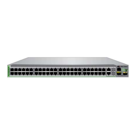
 ....................22 Table 2: Hardware Features of the 8100S Twisted Pair Series ...................24 Table 3: Hardware Features of the Fiber Optic 8100S Series Switches ................27 Table 4: General Specifications of the Fiber Optic Ports .....................29 Table 5: Model Naming Conventions for the Twisted Pair 8100L and 8100S Series Switches ...........33...
For instructions on how to install the 8100S Series switches in a stack configuration, refer to the Stack Installation Guide for the 8100S Series Switches. This preface contains the following sections: “Document Conventions” on page 14 “Contacting Allied Telesis” on page 15 ...
Preface Document Conventions This document uses the following conventions: Note Notes provide additional information. Caution Cautions inform you that performing or omitting a specific action may result in equipment damage or loss of data. Warning Warnings inform you that performing or omitting a specific action may result in bodily injury.
Stand-alone Switch Installation Guide for 8100L and 8100S Series Switches Contacting Allied Telesis If you need assistance with this product, you may contact Allied Telesis technical support by going to the Support & Services section of the Allied Telesis web site at www.alliedtelesis.com/support. You can find links for the following services on this page: 24/7 Online Support —...
Chapter 1 Overview This chapter contains the following sections: “Features” on page 18 “8100L Series Switches” on page 22 “8100S Twisted Pair Series Switches” on page 24 “8100S Fiber Optic Series Switches” on page 27 “Back Panels” on page 30 ...
Chapter 1: Overview Features Here is a list of the switches and their features: 8100L and 8100S Here are the 8100L and 8100S Series switches: Models AT-8100L/8 AT-8100L/8POE AT-8100L/8POE-E AT-8100S/24C AT-8100S/24 AT-8100S/24POE AT-8100S/48 AT-8100S/48POE ...
The SFP slots and 10/100/1000Base-TX twisted pair ports are paired together to form combo ports. For information, refer to “SFP Slots” on page 39. Note SFP transceivers must be purchased separately. For a list of supported transceivers, contact your Allied Telesis distributor or reseller.
Chapter 1: Overview Stacking Ports Here are the basic features of the stacking ports on the 8100S Series switches: Two stacking ports per switch 10Gbps total bandwidth High-definition Multimedia Interface (HDMI) connectors LEDs Here are the port LEDs: Duplex mode and link/activity LEDs for the twisted pair ports ...
Stand-alone Switch Installation Guide for 8100L and 8100S Series Switches Fanless Models Here are the 8100L and 8100S Series switches that do not have fans: AT-8100L/8 Switch AT-8100S/24 Switch AT-8100S/24C Switch AT-8100S/48 Switch ...
The three models in the 8100L Series are listed here: AT-8100L/8 AT-8100L/8POE AT-8100L/8POE-E Hardware Table 1 lists the hardware features of the 8100L Series switches. Features Table 1. Hardware Features of the 8100L Series Switches Feature 8POE 8POE-E Number of 10/100Base-TX Ports Number of 10/100/1000Base-T Ports...
Stand-alone Switch Installation Guide for 8100L and 8100S Series Switches Front Panels The front panels of the 8100L Series switches are shown in Figure 1. AT-8100L/8 AT-8100L/8POE AT-8100L/8POE-E Figure 1. Front Panels of the 8100L Series Switches Front Panel Figure 2 identifies the Fast and Gigabit Ethernet networking ports and the SFP slots on the 8100L Series switches.
Chapter 1: Overview 8100S Twisted Pair Series Switches The five twisted pair models in the 8100S Series are listed here: AT-8100S/24C AT-8100S/24 AT-8100S/24POE AT-8100S/48 AT-8100S/48POE For information on the fiber optic models, refer to “8100S Fiber Optic Series Switches”...
Stand-alone Switch Installation Guide for 8100L and 8100S Series Switches Front Panels The front panels of the 8100S Series switches are shown in Figure 3. AT-8100S/24C AT-8100S/24 AT-8100S/24POE AT-8100S/48 AT-8100S/48POE Figure 3. Front Panels of the 8100S Twisted Pair Series Switches...
Chapter 1: Overview Front Panel Figure 4 identifies the Fast and Gigabit Ethernet networking ports and the SFP slots on the 8100S Series switches. Components 10/100Base-TX Ports Management Panel Combo 10/100/1000Base-T Ports and SFP Slots Figure 4. Networking Ports and SFP Slots on the 8100S Series Switches...
Stand-alone Switch Installation Guide for 8100L and 8100S Series Switches 8100S Fiber Optic Series Switches The three fiber optic models in the 8100S Series are listed here: AT-8100S/16F8-SC AT-8100S/16F8-LC AT-8100S/24F-LC Hardware Table 3 lists the hardware features of the fiber optic 8100S Series switches.
Chapter 1: Overview Front Panels The front panels of the fiber optic switches are shown in Figure 5 and Figure 6 on page 29. AT-8100S/16F8-SC 100Base-FX Fiber 10/100Base-TX Management Twisted Pair Optic Ports with Panel Duplex SC Connectors Ports Combo 10/100/1000Base-T Ports and SFP Slots AT-8100S/16F8-LC...
Stand-alone Switch Installation Guide for 8100L and 8100S Series Switches AT-8100S/24-LC 100Base-FX Fiber Management Optic Ports with Panel Duplex LC Connectors Combo 10/100/1000Base-T Ports and SFP Slots Figure 6. Front Panels of the 8100S Fiber Optic Series Switches (Continued) Fiber Optic Ports Table 4 lists the general specifications of the fiber optic ports on the fiber optic switches.
Chapter 1: Overview Back Panels Figure 7 shows the back panels of the single power supply switches. AT-8100L/8 and AT-8100S/24C Switches AC Power Connector AT-8100L/8POESwitch AC Power Connector Figure 7. Back Panels of the Single Power Supply Switches...
Stand-alone Switch Installation Guide for 8100L and 8100S Series Switches Figure 8 shows the back panels of the dual power supply switches. Dual AC Power Supply Models AC Power AC Power Connector Connector (Power Supply 2) (Power Supply 1) Dual DC Power Supply Models DC Power DC Power Connector...
Figure 9 identifies the components in the management panel on the 8100L Series switches. eco-friendly Button Console Stack ID Management Port Figure 9. 8100L Series Management Panel Figure 10 identifies the components in the management panel on the 8100S Series switches. Console Management Port Stack ID LEDs...
Stand-alone Switch Installation Guide for 8100L and 8100S Series Switches Model Naming Conventions The hardware features of the switches are represented by the letters and numbers in the model names. The conventions for the twisted pair 8100L and 8100S Series switches are identified in Figure 11. Figure 11.
Chapter 1: Overview The conventions are defined in Table 6. Table 6. Model Naming Conventions for the Fiber Optic 8100S Series Switches Convention Definition This is the product name. The letter “S” indicates that the model is stackable. This is the number of 100Base-FX fiber optic ports. The letter “F”...
Stand-alone Switch Installation Guide for 8100L and 8100S Series Switches 10/100Base-TX Twisted Pair Ports The switches have 8, 24, or 48 10/100Base-TX ports. Speed The ports can operate at either 10 or 100 Mbps. The speeds may be set manually using the management software or automatically with Auto- Negotiation (IEEE 802.3u), the default setting.
Chapter 1: Overview Maximum The ports have a maximum operating distance of 100 meters (328 feet). Distance Power Over The 10/100Base-TX ports on the AT-8100S/24POE and AT-8100S/ 48POE Switches support Power over Ethernet (PoE), which is a standard Ethernet whereby DC power is provided by the switch to network devices over the network twisted pair cables.
Stand-alone Switch Installation Guide for 8100L and 8100S Series Switches 10/100/1000Base-T Twisted Pair Ports The switches have two 10/100/1000Base-T ports. These ports are paired with SFP slots to form combo ports. Speed The ports can operate at 10, 100, or 1000 Mbps. The speeds may be set manually using the management software or automatically with Auto- Negotiation (IEEE 802.3u), the default setting.
Chapter 1: Overview The MDI and MDI-X settings do not apply when the ports are operating at 1000 Mbps. Maximum The ports have a maximum operating distance of 100 meters (328 feet). Distance Power Over The 10/100/1000Base-T ports on the AT-8100L/8POE, AT-8100S/24POE and AT-8100S/48POE Switches do not support PoE.
The switches support a variety of short and long distance, 100 and 1000 Mbps fiber optic SFP modules. For a list of supported SFP modules, contact your Allied Telesis representative or visit our web site. The two SFP slots are paired with the two 10/100/1000Base-T ports. The combo ports are listed in Table 9.
Page 40
Chapter 1: Overview Port speed is an exception to the shared settings of the twisted pair port and SFP slot of a combo port. If you disable Auto-Negotiation on the twisted pair port and set the speed and duplex mode manually, the switch reactivates it when an SFP module establishes a link with an end node.
Stand-alone Switch Installation Guide for 8100L and 8100S Series Switches Power Over Ethernet The AT-8100L/8POE, AT-8100L/8POE-E, AT-8100S/24POE, and AT-8100S/48POE Switches feature Power over Ethernet (PoE) on the 10/ 100Base-TX ports. PoE is used to supply power to network devices over the same twisted pair cables that carry the network traffic.
Chapter 1: Overview Powered Device Powered devices are grouped into the five classes listed in Table 10 on page 42. The classes are based on the amount of power the devices Classes require. The switches support all five classes. Table 10. IEEE Powered Device Classes Maximum Power Class Output from a Switch...
Stand-alone Switch Installation Guide for 8100L and 8100S Series Switches The switch can handle different power requirements on different ports. This enables you to connect different classes of PoE equipment to the ports on the switch. Port If the power requirements of the powered devices exceed the switch’s power budget, the switch denies power to some ports based on a system Prioritization called port prioritization.
Chapter 1: Overview Wiring The IEEE 802.3af standard defines two methods by which a PSE, such as the switch, can transmit DC power over twisted pair cables to PDs. These Implementation methods, known as modes A and B, identify the wire strands the switch should use when sending DC power to a PD.
For instructions on how to install a virtual stack of 8100S Series switches, refer to the Stack Installation Guide for the 8100S Series Switches. Note The 8100L Series switches do not support stacking.
Chapter 1: Overview eco-friendly Button You may turn off the port LEDs to conserve electricity when you are not monitoring the switch. The LEDs may be toggled with the eco-friendly button on the front panel of the switch or the ECOFRIENDLY LED and NO ECOFRIENDLY LED commands in the Global Configuration mode of the command line interface.
Stand-alone Switch Installation Guide for 8100L and 8100S Series Switches LEDs Here are descriptions of the switch’s LEDs. 10/100Base-TX The 10/100Base-TX twisted pair ports have link/activity and duplex mode LEDs. Twisted Pair Port LEDs Link/Activity Duplex Mode Duplex Mode Link/Activity Figure 13.
Chapter 1: Overview Here are the LED guidelines: The LEDs do not display port speed. That information may be displayed using the management software. The LEDs do not display PoE information on the AT-8100S/24POE and AT-8100S/48POE Switches. That information may be viewed using the management software.
Stand-alone Switch Installation Guide for 8100L and 8100S Series Switches Table 12. 10/101000Base-T Port LEDs (Continued) State Description Duplex The port is operating in half-duplex mode. Mode Solid green The port is operating in full-duplex mode. 100Base-FX Port Each of the 100Base-FX ports on the AT-8100S/16F8-SC, AT-8100S/ 16F8-LC, and AT-8100S/24F-LC Switches has a single LED, labeled L/A LEDs for Link/Activity.
Chapter 1: Overview SFP Slot LED Each SFP slot has one LED. SFP Slot LEDs Figure 16. SFP Slot LEDs The SFP slot LED is described in Table 14. Table 14. SFP Slot LED State Description Link/Activity The SFP slot is empty or the SFP module has not established a link to a network device.
Stand-alone Switch Installation Guide for 8100L and 8100S Series Switches Stacking Port Each stacking port has one link LED labelled LINK/ACT. LEDs Stacking Port LEDs Figure 17. Stacking Port S1 and S2 LEDs The stacking port LED is described in Table 15. Table 15.
Stack ID Figure 18. Stack ID LED The 8100L Series switches do not support stacking, but they have stack ID LEDs and can be assigned ID numbers because they have the same management software as the 8100S Series switches. Given that you cannot stack 8100L Series switches, the correct ID number for these units is always “0.”...
Stand-alone Switch Installation Guide for 8100L and 8100S Series Switches Console Port The Console port is used to configure the features and parameter settings of the switch. This type of management uses serial RS-232 and is commonly referred to as local or out-of-band management because it is not conducted over your network.
Chapter 1: Overview Power Supplies The 8100L Series switches have one AC power supply. The 8100S Series switches have two AC or DC power supplies, except for the AT-8100S/ 24C Switch, which has one AC power supply. The supplies are not field- replaceable and each has a separate AC or DC connector on the back panels.
The 8100S Series switches have two AC or DC power supply sockets on the back panels, except for the AT-8100S/24C Switch, which has one AC power supply socket. The 8100L Series switches have one AC power supply socket. AC switches are powered on or off by connecting or disconnecting the power cords.
Chapter 2 Beginning the Installation The chapter contains the following sections: “Installation Procedures” on page 58 “Reviewing Safety Precautions” on page 59 “Choosing a Site for the Switch” on page 63 “Unpacking the Switch” on page 64 ...
Chapter 2: Beginning the Installation Installation Procedures You may install the switch on a table or in an equipment rack. Perform these procedures to install the switch on a table: “Reviewing Safety Precautions” on page 59 “Choosing a Site for the Switch” on page 63 ...
Note The indicates that a translation of the safety statement is available in a PDF document titled “Translated Safety Statements” posted on the Allied Telesis website at www.alliedtelesis.com. Warning Class 1 Laser product. L1 Warning Do not stare into the laser beam. L2...
Page 60
Chapter 2: Beginning the Installation Warning Class I Equipment. This equipment must be earthed. The power plug must be connected to a properly wired earth ground socket outlet. An improperly wired socket outlet could place hazardous voltages on accessible metal parts. E4 Note Pluggable Equipment.
Page 61
Stand-alone Switch Installation Guide for 8100L and 8100S Series Switches Caution Risk of explosion if battery is replaced by an incorrect type. Replace only with the same or equivalent type recommended by the manufacturer. Dispose of used batteries according to the manufacturer’s instructions.
Page 62
Chapter 2: Beginning the Installation Warning Reliable earthing of rack-mounted equipment should be maintained. Particular attention should be given to supply connections other than direct connections to the branch circuits (e.g., use of power strips). E37 Warning To reduce the risk of electric shock, the PoE ports on this product must not connect to cabling that is routed outside the building where this device is located.
Stand-alone Switch Installation Guide for 8100L and 8100S Series Switches Choosing a Site for the Switch Observe these requirements when planning the installation of the switch. If you plan to install the switch in an equipment rack, the rack should be safely secured so that it will not tip over.
Allied Telesis sales representative for assistance. Note You should retain the original packaging material in the event you need to return the unit to Allied Telesis 8100L Series The AT-8100L/8, AT-8100L/8POE, and AT-8100L/8POE-E Switches come with the items listed in Figure 19 on page 65.
One 2 m (6.6 ft) local management cable with RJ-45 (8P8C) and DB-9 (D-sub 9-pin) connectors. One short rack mounting bracket One long rack mounting bracket One regional AC power cord Eight bracket screws Figure 19. Components of the 8100L Series Switches...
Chapter 2: Beginning the Installation 8100S Series The 8100S Series switches, except the AT-8100S/24C Switch, come with the components listed in Figure 20. Switches One 8100S Series switch One 2 m (6.6 ft) local management cable with RJ-45 (8P8C) and DB-9 (D-sub 9-pin) connectors.
Stand-alone Switch Installation Guide for 8100L and 8100S Series Switches AT-8100S/24C The AT-8100S/24C Switch comes with the items listed in Figure 21. Switch One AT-8100S/24C Switch One 2 m (6.6 ft) local management cable with RJ-45 (8P8C) and DB-9 (D-sub 9-pin) connectors.
Chapter 3 Installing the Switch on a Table or in an Equipment Rack The procedures in this chapter are: “Installing the Switch on a Table or Desktop” on page 70 “Installing the Switch in an Equipment Rack” on page 71 ...
Chapter 3: Installing the Switch on a Table or in an Equipment Rack Installing the Switch on a Table or Desktop You may install the switch on a table or desktop. Here are the guidelines to selecting a site: The table should be level and stable. ...
63. Here is the procedure for installing the switch in a 19-inch equipment rack. Caution The chassis may be heavy and awkward to lift. Allied Telesis recommends that you get assistance when mounting the chassis in an equipment rack.
Chapter 3: Installing the Switch on a Table or in an Equipment Rack 3. Turn the switch over. 4. For all switches except the AT-8100L/8, AT-8100L/8POE, and AT-8100S/24C Switches, secure the two rack mount brackets to the sides of the switch using the eight bracket screws included with the unit.
The AT-8100L/8, AT-8100L/8POE, AT-8100L/8POE-E, and AT-8100S/ 24C Switches come with one short bracket and one long bracket. Allied Telesis recommends installing the short bracket on the right side and the long bracket on the left side, as you face the front of the unit, so that the stacking ports on the unit align with the same ports on other 8100L and 8100S Switches in the equipment rack.
Chapter 3: Installing the Switch on a Table or in an Equipment Rack Figure 26. Attaching the Brackets to 8100L and AT-8100S/24C Switches for Equipment Rack Installation...
Stand-alone Switch Installation Guide for 8100L and 8100S Series Switches Figure 27. Attaching the Brackets to 8100L and AT-8100S/24C Switches for Equipment Rack Installation (Continued) 5. While another person holds the switch in the equipment rack, secure it using standard equipment rack screws (not provided). Figure 28.
Page 76
Chapter 3: Installing the Switch on a Table or in an Equipment Rack...
Chapter 4 Cabling the Networking Ports This chapter contains the following procedures: “Cabling the Twisted Pair and Fiber Optic Ports” on page 78 “Installing Optional SFP Transceivers” on page 80 ...
Chapter 4: Cabling the Networking Ports Cabling the Twisted Pair and Fiber Optic Ports This section contains the guidelines to cabling the twisted pair and fiber optic ports. Twisted Pair Here are the guidelines to cabling the 10/100Base-TX and 10/100/ 1000Base-T twisted pair ports: Ports The cable specifications for the 10/100Base-TX and 10/100/...
Stand-alone Switch Installation Guide for 8100L and 8100S Series Switches The 10/100/1000Base-T ports must be set to Auto-Negotiation, the default setting, to operate at 1000Mbps. The default duplex mode setting for the ports is Auto-Negotiation. This setting is appropriate for ports connected to network devices that also support Auto-Negotiation for duplex modes.
Chapter 4: Cabling the Networking Ports Installing Optional SFP Transceivers Review the following guidelines before installing optional SFP transceivers in the switch: The SFP slots are part of combo ports, with 10/100/1000Base-T ports. For operational information, refer to “SFP Slots” on page 39. SFP transceivers can be hot-swapped while the switch is powered ...
3. If you are installing the transceiver in the top SFP slot, position the transceiver with the Allied Telesis label facing up. If you are installing the transceiver in the bottom slot, position the transceiver with the label facing down.
Chapter 4: Cabling the Networking Ports Figure 31. Removing the Dust Cover from the SFP Module 6. Verify that the handle on the SFP transceiver is in the upright position, as shown in Figure 32. SFP Handle Figure 32. Positioning the SFP Handle in the Upright Position...
Stand-alone Switch Installation Guide for 8100L and 8100S Series Switches 7. Connect the fiber optic cable to the SFP module, as shown in Figure 33. Figure 33. Connecting the Fiber Optic Cable to the SFP Module 8. Repeat this procedure if you have another SFP transceiver to install.
Page 84
Chapter 4: Cabling the Networking Ports...
Chapter 5 Powering On the Switch This chapter contains the following procedures: “Powering On an AC Switch” on page 86 “Powering On a DC Switch” on page 91 “Setting the Stack ID Number” on page 95 “Starting a Management Session” on page 99 ...
All of the models have two power supplies with separate connectors, except for the AT-8100S/24C Switch and 8100L Series switches, which have just one power supply. Figure 34. Plugging in the AC Power Cord...
Stand-alone Switch Installation Guide for 8100L and 8100S Series Switches Consider the following items as you power on the switch: Connecting the two power cords to power sources that are on different circuits will provide power redundancy to the switch in the event a circuit fails.
Stand-alone Switch Installation Guide for 8100L and 8100S Series Switches Powering On a DC Switch Perform this procedure to power on a DC 8100S Series switch: Warning As a safety precaution, install a circuit breaker with a minimum value of 15 Amps between the equipment and the DC power source. Always connect the wires to the LAN equipment first before you connect the wires to the circuit breaker.
Chapter 5: Powering On the Switch Positive Ground Negative Terminal Terminal Terminal Figure 37. DC Terminal Block 3. With a 14-gauge wire-stripping tool, strip the three wires in the tray cable coming from the DC input power source to 8mm 1mm (0.31 in., ...
Stand-alone Switch Installation Guide for 8100L and 8100S Series Switches Figure 39. Inserting Wires into the DC Terminal Block 5. Connect the positive feed wire to the terminal block marked + (plus). 6. Connect the negative feed wire to the terminal block marked - (minus). Warning Check to see if there are any exposed copper strands coming from the installed wires.
Page 94
Chapter 5: Powering On the Switch computer with a terminal emulator program connected to the Console port on the switch, you will see the messages in Figure 35 on page 89 to Figure 36 on page 90. 11. Repeat this procedure to power on the second power supply. Warning This unit might have more than one power source.
Stand-alone Switch Installation Guide for 8100L and 8100S Series Switches Setting the Stack ID Number After the switch has initialized its management software, examine the Stack ID LED on the front panel and do one of the following: If the LED is displaying “0,” the installation procedure is complete. ...
Chapter 5: Powering On the Switch 2. Connect the other end of the cable to an RS-232 port on a terminal or PC with a terminal emulator program. 3. Configure the terminal or terminal emulator program as follows: Baud rate: 9600 bps (The baud rate of the Console Port is ...
Stand-alone Switch Installation Guide for 8100L and 8100S Series Switches 3. Connect the other end of the cable to the Ethernet port on your computer. 4. Start the Telnet client on your computer and specify the switch’s IP address, 169.254.1.1. 5.
Chapter 5: Powering On the Switch This confirmation prompt in Figure 43 is displayed. *** Warning Stack renumbering requires immediate reboot *** Stack will restart with new Device ID, all ports will have new numbering and any port configurations will probably be lost.
Stand-alone Switch Installation Guide for 8100L and 8100S Series Switches Starting a Management Session You may use the following methods and tools to manage stand-alone 8100L and 8100S Series switches: Local management Telnet client Secure shell client HTTP non-secure and HTTPs secure Web browser ...
Chapter 5: Powering On the Switch Telnet management sessions are not secure and are vulnerable to snooping because the packets exchanged between the switch and your workstation are sent in plain text. The security of the switch may be jeopardized if an intruder captures the packet containing your userrname and password.
Stand-alone Switch Installation Guide for 8100L and 8100S Series Switches You need to assign your management workstation an IP address in the 169.254.n.n subnet or your workstation must have access to that subnet through routing devices. Refer to the AT-8100 Series AlliedWare Plus Command Line Interface User’s Guide for instructions on how to configure the switch for secure HTTPS web browser management.
Page 102
Chapter 5: Powering On the Switch For instructions on the command line interface and the PORT parameter, refer to the AT-8100 Series AlliedWare Plus Command Line Interface User’s Guide.
This chapter contains suggestions on how to troubleshoot the switch if a problem occurs. Note For further assistance, please contact Allied Telesis Technical Support at www.alliedtelesis.com/support. Problem 1: The Stack ID LED on the front of the switch is off.
Page 104
Chapter 6: Troubleshooting Verify that the network device connected to the twisted pair port is powered on and is operating properly. Try connecting another network device to the twisted pair port with a different cable. If the twisted pair port is able to establish a link, then the problem is with the cable or the other network device.
Page 105
Stand-alone Switch Installation Guide for 8100L and 8100S Series Switches Problem 5: Network performance between a twisted pair port on the switch and a network device is slow. Solution: There might be a duplex mode mismatch between the port and the network device.
Appendix A Technical Specifications Physical Specifications Dimensions (H x W x D) Table 17. Product Dimensions AT-8100L/8 4.4 cm x 33.0 cm x 20.3 cm AT-8100L/8POE (1.7 in. x 13.0 in. x 8.1 in.) AT-8100L/8POE-E AT-8100S/24C AT-8100S/24 4.4 cm x 44.1 cm x 29.1 cm AT-8100S/48 (1.7 in.
Stand-alone Switch Installation Guide for 8100L and 8100S Series Switches Table 28. Fiber Optic Port Specifications for the AT-8100S/16F8-SC Switch (Continued) Receiver Wavelength 1310 nm Sensitivity Maximum: -31.8 dBm Maximum Input Power Minimum: -14 dBm Table 29 lists the specifications of the 100Base-FX fiber optic ports on the AT-8100S/16F8-LC and AT-8100S/24F-LC Switches.
Appendix A: Technical Specifications RJ-45 Style Serial Console Port Pinouts Table 30 lists the pin signals of the RJ-45 style serial Console port. Table 30. RJ-45 Style Serial Console Port Pin Signals Signal Looped to pin 8. Looped to pin 7. Transmit Data Ground Ground...
Page 115
Stand-alone Switch Installation Guide for 8100L and 8100S Series Switches Table 31. Stacking Port Pin Signals (Continued) S1 Port S2 Port Transmit data1+ Receive data1+ Ground Ground Transmit data1- Receive data1- Receive data0+ Transmit data0+ Ground Ground Receive data0- Transmit data0- Not connected Not connected Ground...