Table of Contents
Advertisement
Quick Links
Operating Instructions
- For portable spray application of architectural paints and coatings -
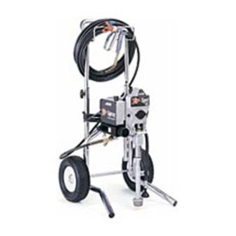
1900 Plust Airless Paint Sprayer
3000 psi (207 bar, 20.7 MPa) Maximum Working Pressure
Important Safety Instructions
Read all warnings and instructions in this manual.
Save these instructions.
ti7508a
Hi Boy 233782
Series A, B, C, D, E, F
. . . . . . .
309423
. . . . . . .
309971
. . . . . . .
309428
Model 233782 (Series A, B)
Model 246649 (Series A, B, C, D)
. . . . . . .
311062
Model 233782 (Series C, D, E, F)
ti8027a
Stand 246649
Series A, B, C, D
309427K
Advertisement
Table of Contents

Related Manuals for ASM Zip-Spray 1900 Plus


Summary of Contents for ASM Zip-Spray 1900 Plus
-
Page 1: Operating Instructions
309427K Operating Instructions - For portable spray application of architectural paints and coatings - 1900 Plust Airless Paint Sprayer 3000 psi (207 bar, 20.7 MPa) Maximum Working Pressure ..309423 Important Safety Instructions Read all warnings and instructions in this manual. Save these instructions. -
Page 2: Specifications
Specifications This equipment is not intended for use with flammable or combustible materials used in places such as cabinet shops or other “factory” or fixed locations. If you intend to use this equipment in this type of application, you must comply with NFPA 33 and OSHA requirements for the use of flammable and combustible materials. - Page 3 WARNING ELECTRIC SHOCK HAZARD Improper grounding, setup, or usage of the system can cause electric shock. D Turn off and disconnect power cord before servicing equipment. D Use only grounded electrical outlets D Use only 3--wire extension cords. D Ensure ground prongs are intact on sprayer and extension cords. D Do not expose sprayer to rain.
-
Page 4: Grounding And Electric Requirements
Grounding and Electric Requirements The sprayer must be grounded. Grounding reduces the risk of static and electric shock by providing an escape wire for the electrical cur- rent due to static build up or in the event of a short circuit. D The sprayer requires a 120V AC, 60 Hz, 15A circuit with grounding receptacle. -
Page 5: Thermal Overload
Grounding and Electric Requirements D Ground the metal pail by clamping one end of ground wire to pail and the other end to ground, such as a water pipe. ti5851a D Maintain grounding continuity when flushing or relieving pressure by hold- ing metal part of spray gun firmly to side of a grounded metal pail, then trigger gun. -
Page 6: Pressure Relief Procedure
Pressure Relief Procedure Follow Pressure Relief Procedure when you stop spraying and before cleaning, checking, servicing or transporting equipment. 1. Turn power switch OFF and unplug power cord. 2. Turn Spray--Prime/Drain valve to PRIME/DRAIN to relieve pressure. PRIME 3. Turn pressure to lowest setting. Hold metal part of gun firmly to a grounded metal pail. -
Page 7: Power Switch
Component Identification Pressure Control Power Switch Increase Decrease Pressure Pressure TI3183a Filter Drain Tube Suction Tube Suction tube + drain tube = Siphon tube set ti7508a Prime Valve Fluid Outlet ti6778a Spray Gun Trigger Safety Prime/drain position safety ON safety OFF Take trigger safety OFF Set trigger safety ON when not spraying. - Page 8 Setup 1. Connect airless hose to sprayer. Tighten securely. 2. Connect other end of hose to gun. ti6766a 3. Tighten securely. ti6767a 4. Remove tip guard. ti6768a 309427...
- Page 9 5. Check inlet strainer for clogs and debris. 6. Fill throat packing nut with ASM Packing Seal to prevent premature packing wear. Do this each time you spray. ti6012a 309427...
- Page 10 7. Turn power OFF. 8. Plug power supply cord into a properly grounded electrical outlet. 9. Turn prime valve down. 10. Place siphon tube set in grounded metal pail partially filled with flushing fluid. Attach ground wire to pail and to true earth ground.
- Page 11 Startup 1. Turn pressure control to lowest pressure. 2. Turn power ON. 3. Increase pressure enough to start motor and allow fluid to circulate through drain tube for 15 seconds; turn pressure down. 15 SEC 4. Turn prime valve horizontal. Take trigger safety OFF.
- Page 12 6. Place siphon tube in paint pail. PAINT 7. Trigger gun again into flushing fluid pail until paint appears. Set trigger safety ON. Assemble tip and guard, page 13. ti6763a FLUSH safety ON General Surfaces Tip Recommendations Chart _____ Fan Width (in.) _____ at 12 in.
-
Page 13: Tip And Guard Assembly
Tip and Guard Assembly 1. Insert tip seal and gasket. Make sure curvature of tip seal mates with curvature of tip cylinder. ti6770a 2. Insert tip. ti6771a 3. Screw assembly onto gun. Hand tighten. Repeat Startup 4 and 5. ti6772a 309427... -
Page 14: Clearing Tip Clogs
Spray Test Pattern 1. Trigger gun and spray test pattern. Slowly adjust pressure to eliminate heavy edges. Use smaller tip size if pressure adjustment can not eliminate heavy edges. heavy edges 2. Hold gun perpendicular, 10--12 in. (25--30 cm) from surface. Spray back and forth. Use strokes overlapped by 50%. - Page 15 Cleanup 1. Turn power OFF. 2. Turn pressure to lowest setting. Trigger gun to relieve pressure. PAINT ti6740a 3. Turn prime valve down to prime position. 4. Remove filter assembly and assemble gun without filter. 309427...
- Page 16 5. Remove guard and Uni--tip. ti6768a 6. Clean filter, guard and Uni--tip in flushing fluid. FLUSH ti6776a 7. Remove siphon tube set from paint and place in flushing fluid. Use water for water base paint and mineral spirits for oil base paint. PAINT FLUSH 8.
- Page 17 9. Turn power ON. 10. Turn prime valve horizontal to spray position. 11. Hold gun against paint pail. Take trigger safety OFF. Trigger gun and increase pressure until flushing fluid appears. PAINT 12. Move gun to flushing pail, hold gun against pail, trigger gun to thoroughly flush system.
- Page 18 14. Raise siphon tube above flushing fluid and run sprayer for 15 to 30 seconds to drain fluid. Turn power OFF. PAINT FLUSH Note: If flushing with water, flush again with mineral spirits or Pump Shield, but do not repeat step 8 or 14. This leaves a protective coating in the system to help prevent freezing or corrosion.
-
Page 19: Maintenance
Inspect, clean and replace as needed Manifold filter (Hi--Boy model only), gun filter and inlet stainer. Wet cup for leakage, tighten if needed. ASM Packing Seal level. Gun trigger safety. Tip wear, replace if necessary. Electric cord and plug. Weekly: Check tightness of wet cup. -
Page 20: Asm Standard Warranty
ASM distributor to the original purchaser for use. With the exception of any special, extended, or limited warranty published by ASM, ASM will, for a period of twelve months from the date of sale, repair or replace any part of the equipment determined by ASM to be defective.
Need help?
Do you have a question about the Zip-Spray 1900 Plus and is the answer not in the manual?
Questions and answers