Table of Contents
Advertisement
Quick Links
Repair Instructions and Parts List
1900 Airless Paint Sprayer
3000 psi (207 bar, 20.7 MPa) Maximum Working Pressure
Hi-Boy
Model 233782, A, B
Stand
Model 246649, A
Related manuals
. . . . . . .
. . . . . . .
. . . . . . .
. . . . . . . . . . . . . . . . . . . . . . . . . . . . . . . . . . . . .
. . . . . . . . . . . . . . . . . . . . . . . . . . . . . . . .
. . . . . . . . . . . . . . . . . . . . . . . . . . . . . . . . . . . . .
309427
309428
10803
Table of Contents
. . . . . . . . . . . .
. . . . . . . . . . . . . . . . . . . . . .
. . . . . . . . . . . . . . . . . . . . .
. . . . . . . . . . . . . . . . . . . .
. . . . . . . . . . . . . . . . . . . . . . .
3
5
5
4
. . . . . . . . . . . . . . . . . . . . . . . . . . . . . . . . . . . . . . . .
10
. . . . . . . . . . . . . . . . . . . . . . . . . . . . . . . .
10
. . . . . . . . . . . . . . . . . . . . . . . . . . . . . . . .
12
14
309423
Hi-Boy
233782
. . . . . . . . . . . . . . . . . . . .
. . . . . . . . . . . . . . . . . . . . . . . . . . . .
. . . . . . . . . . . . . . .
. . . . . . . . . . . . . . . . . . . . . . . . . . .
Rev. C
ti1644b
17
18
19
20
26
28
28
Advertisement
Table of Contents

Subscribe to Our Youtube Channel
Related Manuals for ASM Zip-Spray 233782


Summary of Contents for ASM Zip-Spray 233782
-
Page 1: Table Of Contents
..... . . ASM Phone Number ...... - Page 2 Do not smoke in spray area. PRESSURIZED EQUIPMENT HAZARD This sprayer is capable of Use only ASM airless paint hoses. producing up to 2800 psi (19 MPa, 193 bar) Use outdoors or in a well-ventilated area. maximum working pressure. To avoid...
-
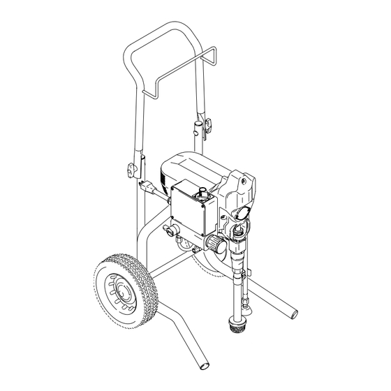
Page 3: Component Function And Identification
Component Identification and Function ti1644b Fig. 1 Motor DC motor, permanent magnet, fan cooled Drive Assembly Transfers power from DC motor to displacement pump Displacement Pump Transfers fluid to be sprayed from source through spray gun Fluid Outlet Spray gun is connected here Prime Valve Used to prime and drain sprayer (also relieves fluid outlet pressure) when open... -
Page 4: General Repair Information
General Repair Information Pressure Relief Procedure 1. Keep all screws, nuts, washers, gaskets, and electrical fittings removed during repair proce- dures. These parts are not normally provided with WARNING replacement assemblies. INJECTION HAZARD WARNING System pressure must be manually relieved to prevent system from starting ELECTRIC SHOCK HAZARD or spraying accidentally. -
Page 5: Grounding
Grounding WARNING grounded outlets Improper installation or alteration of grounding plug results in risk of electric shock, fire or explosion that could cause serious injury or death. 1. 100–120 Vac models require a 50/60 Hz, 15A circuit with a grounding receptacle. See Fig. 2. grounding prong Fig. - Page 6 Troubleshooting MOTOR WON’T OPERATE (Continued) TYPE OF PROBLEM WHAT TO CHECK WHAT TO DO If check is OK, go to next check When check is not OK refer to this column Basic Electrical Problems 5. That motor leads are securely fastened and 5.
- Page 7 Troubleshooting LOW OR FLUCTUATING OUTPUT TYPE OF PROBLEM WHAT TO CHECK WHAT TO DO If check is OK, go to next check When check is not OK refer to this column Low Output 1. For worn spray tip. 1. Follow Pressure Relief Procedure, then replace tip.
- Page 8 Troubleshooting LOW OR FLUCTUATING OUTPUT TYPE OF PROBLEM WHAT TO CHECK WHAT TO DO If check is OK, go to next check When check is not OK refer to this column Motor runs and pump strokes 1. Paint supply. 1. Refill and reprime pump. 2.
- Page 9 Troubleshooting MOTOR IS HOT AND RUNS INTERMITTENTLY TYPE OF PROBLEM WHAT TO CHECK WHAT TO DO If check is OK, go to next check When check is not OK refer to this column Motor is hot and runs intermit- 1. Determine if sprayer was operated at high 1.
-
Page 10: Spin Test
Spin Test Setup Armature, Brushes, and Motor Wiring Open Circuit Test (Continuity) 1. Connect red and black motor leads together with Electric Shock Hazard, page 4. test lead. Turn motor fan by hand at about two revolutions per second. 2. If uneven or no resistance, check for: broken brush To check armature, motor winding and brush electrical springs, brush leads, motor leads;... - Page 11 Motor Brush Replacement 6. Fig. 5. Insert brush (B). Push clip (A) until it snaps 8. Inspect commutator for excessive pitting, burning into place and secures brush. or gouging. A black color on commutator is normal. Have commutator resurfaced by a motor repair shop if brushes wear too fast.
-
Page 12: On/Off Switch Replacement
On/Off Switch Replacement Removal Installation 1. Install new ON/OFF switch (23). Install locking ring Relieve pressure; page 4. (24) and toggle boot (25). 2. Fig. 6. Remove four screws (18) and pressure control cover (39). 2. Connect two wires (A) to ON/OFF switch. 3. - Page 13 On/Off Switch Replacement 120 Vac Wiring Diagram (Capacitor on Motor) ON/OFF 233782, A Switch L2 L1 Power Plug Black Pressure Transducer White Green Yellow from Motor Potentiometer Red (+) Black (–) Capacitor TI0060 Wiring Diagram ON/OFF Switch White (Capacitor on PC board) 233782, B Capacitor 246649, A...
-
Page 14: Pressure Control Repair
Pressure Control Repair Motor Control Board Diagnostics Note: Keep a new transducer on hand to use for test. 1. Remove four screws (18) and cover (39). 2. Turn ON/OFF switch ON. CAUTION 3. Observe LED operation and reference following table: Do not allow sprayer to develop fluid pressure with- out transducer installed. - Page 15 Pressure Control Repair Motor Control Board Removal Installation Refer to Fig. 6 and 7. 1. Clean pad on rear of motor control board. Apply small amount of thermal compound 073019 to pad. 2. Fig. 6. Install motor control board (35) with five Relieve pressure;...
- Page 16 Pressure Control Repair Pressure Control Transducer Pressure Adjust Potentiometer Removal Removal Refer to Fig. 6 and 7. Refer to Fig. 6 and 7. Relieve pressure; page 4. Relieve pressure; page 4. 2. Remove four screws (18) and cover (39). 2. Remove four screws (18) and cover (39). 3.
-
Page 17: Drive Housing Replacement
Drive Housing Replacement 4. Remove two front screws (22). CAUTION 5. Remove two back screws (22). Do not drop gear cluster (7) when removing drive housing (10). Gear cluster may stay engaged in 6. Pull drive housing (10) off of motor (1). motor front end bell or drive housing. -
Page 18: Motor Replacement
Motor Replacement Disassembly 7. Remove three screws (22) behind board and remove control housing (21). 8. Remove four screws (22) and motor (1) from Relieve pressure; page 4. frame (63). 2. Remove pump (13), Displacement Pump Assembly Replacement, page 17. 1. -
Page 19: Displacement Pump Replacement
1. Fig. 12. Extend pump piston rod fully. Apply grease to top of pump rod at (A) or inside connecting rod. TI0063 Fig. 13 7. Fig. 14. Fill packing nut with ASM Packing Seal until fluid flows onto top of seal. TI0062 Fig. 12 2. -
Page 20: Parts
Parts Drawing – Sprayer Zip Spray 1900 Sprayer Model 246649 PARTS, PAGE 24 Ref 19 84 Ref Ref 84 Ref 78 9540d 309423... - Page 21 Parts List – Sprayer Zip Spray 1900 Sprayer Model 246649 NO. PART NO. DESCRIPTION NO. PART NO. DESCRIPTION 245893† MOTOR, 120 vac 241858 FRAME, stand mount 115525 BLADE, fan motor 195177 HOLDER, suction tube 243219 GEAR, combination 107310 PLUG, tubing 243218 CRANK SHAFT 115506...
- Page 22 Parts Drawing – Sprayer Zip Spray 1900 Sprayer Model 233782 * Parts 130 through 134 not used on later models. See Parts List – Sprayer, page 23. 130* 131* 132* 133* 134* PARTS, PAGE 24 ti1634b 309423...
- Page 23 Parts List – Sprayer Zip Spray 1900 Sprayer Model 233782 NO. PART NO. DESCRIPTION NO. PART NO. DESCRIPTION KIT, MOTOR, 120 vac 101242 RING, retaining, external 242009† 233782, A 107310 PLUG, tubing 245893† 233782, B 241938 HANDLE, cart 115525 BLADE, fan motor 106062 WHEEL, semi–pneumatic 243219...
- Page 24 Parts Drawing – Sprayer Ref 1 Ref 45 9538A 309423...
- Page 25 Parts List – Sprayer Zip Spray 1900 Sprayer NO. PART NO. DESCRIPTION NO. PART NO. DESCRIPTION 115492 SCREW, slot hd, hex, washer hd 115498 SCREW, slot hd, hex, washer hd 276539 HOUSING, control BOARD, control 115495 SCREW, slot hd, hex, washer hd 241989 233782, A 195429...
-
Page 26: Technical Data
Parts List – Sprayer Wiring Diagram ON/OFF (Capacitor on PC Board) Switch White 233782, B 246649, A Capacitor M– Black Power Green Plug Red (+) Pressure Black (–) Transducer from Motor Yellow ti2159a Potentiometer Fig. 16 Technical Data 100–120V, ∅, 220–240V, ∅, Generator Motor HP... - Page 27 Notes 309423...
-
Page 28: Asm Warranty
ASM distributor to the original purchaser for use. With the exception of any special, extended, or limited warranty published by ASM, ASM will, for a period of twelve months from the date of sale, repair or replace any part of the equipment determined by ASM to be defective.
Need help?
Do you have a question about the Zip-Spray 233782 and is the answer not in the manual?
Questions and answers