Table of Contents
Advertisement
Quick Links
Operation
Interior Texture Sprayers
™
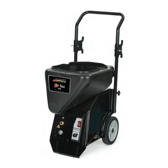
Zip-Tex
Models:
254983
60 psi (4.2 bar) Maximum Fluid Working Pressure
Important Safety Instructions.
Read all warnings and instructions in this
manual. Save these instructions.
Related Manuals
311969
311774
900
For Water-Based Materials Only
311766B
Model 254983 Shown
US
Conforms to ANSI/UL
standard 1450
ti9993a
C
Advertisement
Table of Contents

Related Manuals for ASM Zip-Tex 900


Summary of Contents for ASM Zip-Tex 900
- Page 1 Operation Interior Texture Sprayers ™ Zip-Tex 311766B For Water-Based Materials Only Models: 254983 60 psi (4.2 bar) Maximum Fluid Working Pressure Important Safety Instructions. Read all warnings and instructions in this manual. Save these instructions. Related Manuals 311969 311774 ti9993a Model 254983 Shown Conforms to ANSI/UL standard 1450...
- Page 2 Warnings Warnings The following are general warnings related to the setup, use, grounding, maintenance and repair of this equipment. Additional, more specific warnings may be found throughout the body of this manual where applicable. Symbols appearing in the body of the manual refer to these general warnings. When these symbols appear through the manual, refer back to these pages for a description of the specific hazard.
- Page 3 Warnings Warnings Electric Shock Hazard To reduce the risk of electric shock: • Be sure sprayer is adequately grounded through electrical outlet. • Use only 3-wire, extension cords. • Make sure ground prongs are intact on sprayer and extension cords. Improper installation of ground- ing plug will result in a risk of electrical shock, fire or explosion that could cause serious injury or death.
- Page 4 Warnings CAUTION • Water or material remaining in unit when temperatures are below freezing can damage motor and/or delay pump startup. Do not allow unit to freeze. • Before adding material or starting unit in cold weather, run warm water through pump. ti8713a To ensure water and material are completely drained out of unit: 1.
-
Page 5: Component Identification
Component Identification Component Identification ti9995a Item Component Item Component Hose Rack/Cord Wrap Touch-Up Hopper (3/4 Gallon) Power Cord Gun Plug Clip ™ Gun Plug RotoFlex II Pump (inside) Hopper Fitting (fluid inlet) Nozzle (Nozzle Selection, page 11) Material Hose Outlet Hose Plug Air Hose Outlet Material/Air Hose... - Page 6 Preparation Preparation Pressure Relief Procedure Check with a qualified electrician or serviceman if grounding instructions are not completely understood, To reduce risk of injury, follow this procedure or if in doubt as to whether the product is properly whenever you see this symbol throughout this grounded.
- Page 7 Setup Setup Important • To increase pump life, turn power off when not spraying. • Do not allow material to dry inside pump, hoses, gun or spray system. 4. Connect material hose to gun. Texture Spraying (material supplied from unit) When using material ti8705a supplied from unit,...
- Page 8 Setup 9. Close gun air valve. Touch Up Hopper Attachment The Hose Plug must be securely fastened to bottom of gun when using the Touch Up Hopper. Gun plug must be removed from top of gun. ti8712a 10. Point gun into waste bucket and pull trigger to pump ti8701a water through the system.
- Page 9 Setup 6. Turn selector knob to HOPPER GUN. 9. To achieve uniform spray pattern, adjust air valve and flow adjustment nut on gun. If you do not achieve the desired spray pattern, change nozzles (see page 11). ti8728a 7. Open gun air valve. ti9996a ti8528a 8.
-
Page 10: Mixing Material
Mixing Material Mixing Material 5. Observe the ball on the material. When the material Correct material mixture is essential. The pump is thin enough to spray the ball will sink completely will not operate if the mixture is too thick. into the mixture. -
Page 11: Spray Techniques
Spray Techniques Spray Techniques Recommended Nozzle Selection Chart To Get Less Material Try one or a combination of these methods: Application Nozzle Size Air Volume • Open air valve. Simulated 6 mm, white medium to (fine to medium) Acoustic 8 mm, gray high (coarse) •... -
Page 12: Shut Down And Clean-Up
Shutdown and Cleanup Shutdown and Cleanup Keep pump and hose clean when switching between simulated acoustic, knockdown and orange peel applications. A dirty pump can release particles of texture into the finish. CAUTION • To increase pump life, turn power off when not spraying. •... - Page 13 Shutdown and Cleanup Removing Material Hopper From Sprayer 5. Turn power switch ON. The material hopper can be removed for cleaning. To remove material hopper: 1. Loosen bottom fitting. ti8711a 6. Open gun air valve. ti8702a 2. Lift and twist material hopper to remove from unit. ti8528a 7.
-
Page 14: Troubleshooting
Refer to Grounding and Electrical Requirements, page 6. Gun needle plugged Clean needle and retry. Worn compressor Replace compressor. Contact an authorized ASM Service Center. Lines not connected Check all quick disconnect connec- tions to gun and hoses Damaged hose Replace hose... - Page 15 Troubleshooting Problem Cause Solution Speed of application slow or slower Material too thick Thin material. Nozzle too small Change nozzles to a larger size. See Recommended Nozzle Selection Chart, page 11. Too much air being used. Partially close gun air valve to reduce air flow.
-
Page 16: Technical Data
Technical Data Technical Data Main unit power requirements 120 Vac, 60 Hz, 15A, 1 phase Maximum fluid working pressure 60 psi, (4.2 bar) Maximum air working pressure 50 psi, (3.5 bar) Compressor specifications Universal motor thermally protected, oil-less Compressor air displacement 4.0 scfm at 45 psi Generator required 3500W minimum... - Page 17 Notes Notes 311766B...
-
Page 18: Asm Standard Warranty
ASM, ASM will, for a period of twelve months from the date of sale, repair or replace any part of the equipment determined by ASM to be defective. This warranty applies only when the equipment is installed, operated and maintained in accordance with ASM’s written recommendations.
Need help?
Do you have a question about the Zip-Tex 900 and is the answer not in the manual?
Questions and answers