Table of Contents
Advertisement
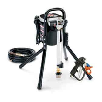
Operation
Airless Sprayers
US Patent No.1184US3
- For portable spray applications of architectural
paints and coatings -
Use water based or mineral spirit-type material only.
Do not use with materials having flash points lower
than 70°F (21°C). For more information about your
material, request MSDS from the distributor or retailer.
ASM ESP
Model 248772
ASM 1700
Model 233789
(Specifications, page 2.)
Important Safety Instructions
Read all warnings and instructions in this manual.
Save these instructions. See page 2 for models
and series information, including dispense rates,
recommended hose length, guns and maximum
working pressure.
311139B
ASM 1500
Model 248672
ASM 1900
Model 248673
Advertisement
Table of Contents

Related Manuals for ASM Zip-Spray ESP


Summary of Contents for ASM Zip-Spray ESP
- Page 1 Do not use with materials having flash points lower recommended hose length, guns and maximum than 70°F (21°C). For more information about your working pressure. material, request MSDS from the distributor or retailer. ASM ESP ASM 1500 Model 248772 Model 248672 ASM 1900...
-
Page 2: Specifications
Hose Length and Model No. Series gpm (lpm) Diameter Model 0.24 gpm 25 ft x 1/4 in. 2800 ASM ESP (0.91 lpm) (8 m x 4.8 mm) 248772 0.27 gpm 25 ft x 1/4 in. 3000 ASM 1500 (1.02 lpm) (8 m x 6.3 mm) - Page 3 Warnings Warnings The following Warnings are for the safe setup, use, grounding, maintenance and repair of this equipment. The excla- mation point symbol alerts you to a general warning and the hazard symbols refer to procedure-specific risks. Refer back to these Warnings. Additional, product-specific warnings may be found throughout the body of this manual where applicable.
- Page 4 Warnings WARNING EQUIPMENT MISUSE HAZARD Misuse can cause death or serious injury. • Do not operate the unit when fatigued or under the influence of drugs or alcohol. • Do not exceed the maximum working pressure or temperature rating of the lowest rated system component.
-
Page 5: Installation
Installation Installation Grounding and Electric Spray gun: ground through connection to a properly grounded fluid hose and pump. Requirements Fluid supply container: follow local code. Solvent pails used when flushing: follow local code. Use only conductive metal pails, placed on a grounded surface such as concrete. -
Page 6: Component Identification
Component Identification Component Identification Electric motor (inside enclosures) Provides mechanical power to pump. Power switch Manually turns ON and OFF electric power to motor (I is ON and 0 is OFF. Pressure control knob Manually increases (turn clockwise) and decreases (turn counter-clockwise) fluid pressure in pump, hose, and spray gun. - Page 7 Component Identification Sprayers Connect cart handles on 1700 and 1900 as follow: 1. Position handle on frame as shown and align bolt holes in handle with bolt holes in frame. 2. Run bolts through holes with heads pointing toward each other, and hand tighten wingnuts. NOTE: For space-saving configuration, loosen, (but do not remove) wingnuts.
-
Page 8: Operation
Operation Operation Pressure Relief Procedure 4. Engage trigger lock. See Trigger Lock, page 8. Follow this procedure when you stop spraying and before cleaning, checking, servicing, or transporting Leave Spray-Prime/Drain equipment. valve in the PRIME/DRAIN position until you are ready to spray again. - Page 9 Setup Setup 1. Unscrew tip and guard 4. Connect other end of hose to sprayer. assembly from gun. 2. Uncoil hose and connect one end to gun. If hose is already connected, make sure connec- Need tions are tight. 6766 5.
-
Page 10: Oil- Or Water-Based Materials
Priming Priming Oil- or Water-based Materials 4. If spraying oil-based materials, submerge suction tube in mineral spirits or compatible oil-based clean- ing solvent. To spray water-based materials after spraying If spraying water-based materials, submerge suc- oil-based materials, flush the system thoroughly tion tube in water. -
Page 11: Pump Check Valves
SPRAY. to the pump. To determine if the inlet valve ball is sticking, unscrew inlet valve from pump and check it. ASM Motor stopping indicates pump and hose are 1500, 1700 and 1900 sprayers allow for inlet valve primed with paint. -
Page 12: Unclogging Spray Tip
Installing Tip and Base Installing Tip and Base 3. Screw tip and guard assembly on gun. Tighten retaining nut. 1. Engage trigger lock. 300/400 Series 200 Series Lock Unclogging Spray Tip Lock To avoid fluid splashback: • Never pull gun trigger when arrow-shaped han- dle is between SPRAY and UNCLOG positions. -
Page 13: Tip Selection
Tip Selection Tip Selection Selecting Tip Hole Size HINTS: • As you spray, the tip wears and enlarges. Starting Tips come in a variety of hole sizes for spraying a range with a tip hole size smaller than the maximum will of fluids. - Page 14 Tip Selection Uni-Tip Selection Chart Fan Width Fan width is the size of the spray pattern, which deter- mines the area covered with each stroke. For a given tip hole size, narrower fans deliver a thicker coat, and wider Part Fan Width 12 in.
-
Page 15: Spraying Techniques
Spraying Techniques Spraying Techniques Preventing Excessive Tip Wear This sprayer is set up for most airless spraying applica- tions. Details on tip selection, tip wear, coat thickness, etc. are provided on page 13. • Spray should be atomized (evenly distributed, no gaps at edges). -
Page 16: Getting Started With Basic Techniques
Spraying Techniques Getting Started With Basic Triggering Gun Techniques Pull trigger after starting stroke. Release trigger before end of stroke. Gun must be moving when trigger is pulled and released. Practice spraying on a piece of scrap or cardboard before you begin spraying. •... -
Page 17: Shutdown And Cleaning
Shutdown and Cleaning Shutdown and Cleaning Pail Flushing 5. Trigger gun into waste pail to relieve pressure in hose. 6. Remove tip and guard assembly • For short term shutdown periods (overnight to from gun and one week) refer to Short Term Storage, page place in flushing fluid. - Page 18 Shutdown and Cleaning ™ 6. Remove tip and guard assembly from gun and place 13. Fill unit with Pump Defender in flushing fluid. storage fluid. Read Long Term Storage, page 21. Pump Defender. Zip-Flush Cleaning 7. Screw Zip-Flush attachment to garden hose. Open valve.
- Page 19 Shutdown and Cleaning 13. Align arrow on 19. Turn power switch OFF. sprayer with pail symbol on Pressure Control knob until pump starts. 20. Close Zip-Flush attachment. Turn off garden hose. 14. Open lever on Zip-Flush attach- ment. 21. Unscrew Zip-Flush attachment from suction tube.
- Page 20 Shutdown and Cleaning 3. Check pump fluid filter for debris. If needed, clean 5. Tighten outlet fitting and filter with water and a soft brush. reconnect hose to sprayer. Gun Fluid Filter Clean gun fluid filter with compatible solvent and a brush every time you flush the system.
-
Page 21: Short-Term Storage
Storage Storage Short Term Storage Long Term Storage (up to 2 days) (longer than 1 week) 1. Place suction and drain tube in Always circulate Pump Defender paint can. storage fluid through system 2. Cover can and hoses tightly with after cleaning. - Page 22 Storage 5. Turn pressure control knob 2. Coil hose. Leave it clockwise until the pump turns connected to sprayer. 6. When storage fluid comes out of prime tube (5-10 seconds) turn power switch OFF. 3. Wrap airless hose around hose wrap (1700 and 1900 models).
-
Page 23: Troubleshooting
Troubleshooting Troubleshooting Check everything in this Troubleshooting Table before you bring the sprayer to an ASM authorized service center. Refer to Component Identification, page 6, for reference letters used in table. Problem Cause Solution Power switch is on and sprayer is Pressure is set at zero pressure. - Page 24 Tighten suction tube connection (K). Inspect for cracks or vacuum leaks. Spray-Prime/Drain Valve is plugged. Clean/replace drain tube as neces- sary. Take sprayer to ASM authorized service center if valve is plugged. Spray gun stopped spraying. Spray tip is clogged.
- Page 25 Troubleshooting Problem Cause Solution Pump cycles, but paint only dribbles Pressure is set too low. Slowly turn Pressure Control Knob or spurts when spray gun is trig- (C) clockwise to increase pressure gered. setting and verify if sprayer pressure increases. Spray tip is clogged.
- Page 26 • Replace extension cord. Fan pattern varies dramatically while Pressure control switch is worn and Take sprayer to ASM authorized ser- spraying. causing excessive pressure variation. vice center. Sprayer does not turn on promptly when resuming spraying.
-
Page 27: Maintenance And Service
When packings wear, paint will begin to leak down out- side of pump. Replace pump packings at the first sign of leaking or additional damage could occur. Get pump repair kit and install according to instructions on kit packaging. Consult an ASM authorized service center. 311139B... -
Page 28: Technical Data
Technical Data Technical Data ASM ESP ASM 1500 ASM 1700 ASM 1900 Working pressure 0-2800 psi (0-19 MPa, 0-3000 psi (0-21 MPa, 0-3000 psi (0-21 MPa, 0-3000 psi (0-21 MPa, range 0 -193 bar) 0-207 bar) 0-207 bar) 0-207 bar) Electric motor 6.5 AMP (open frame,... - Page 29 Notes Notes 311139B...
-
Page 30: Asm Standard Warranty
With the exception of any special, extended, or limited warranty published by ASM, ASM will, for a period of twelve months from the date of sale, repair or replace any part of the equipment determined by ASM to be defective.
Need help?
Do you have a question about the Zip-Spray ESP and is the answer not in the manual?
Questions and answers