Table of Contents
Advertisement
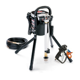
Operating Instructions
– For portable spray applications of architectural
paints and coatings –
Model 248772, Series A
2800 psi (193 bar, 19 MPa) Maximum Working Pressure
Important Safety Instructions
Read all warnings and instructions in this
manual. Save these instructions.
Use water based or mineral spirit–type material
only. Do not use materials having flash points lower
than 70_ (21_). For information about your material
request MSDS from distributor or retailer.
(Specifications, page 2)
ti3587B
310749
Rev. C
Advertisement
Table of Contents

Related Manuals for ASM Zip-Spray ESP


Summary of Contents for ASM Zip-Spray ESP
-
Page 1: Operating Instructions
Operating Instructions 310749 Rev. C – For portable spray applications of architectural paints and coatings – (Specifications, page 2) Model 248772, Series A 2800 psi (193 bar, 19 MPa) Maximum Working Pressure Important Safety Instructions Read all warnings and instructions in this manual. -
Page 2: Specifications
Specifications This equipment is not intended for applications in places such as cabinet shops or other “factory”, fixed locations or for repetitive applications. If you intend to use this equipment in this type of application, you must com- ply with NFPA 33 and OSHA requirements which have similar expectations. The following are general warnings related to the setup, use, grounding, maintenance, and repair of this equipment. - Page 3 MSDS from distributor or retailer. Check equipment daily. Repair or replace worn or damaged parts immediately with genuine ASM replacement parts only. Do not alter or modify equipment. Use equipment only for its intended purpose. Call your Graco distributor for information.
-
Page 4: Grounding And Electric Requirements
Grounding and Electric Requirements The sprayer must be grounded. Grounding reduces the risk of static and electric shock by providing an escape wire for the electrical current due to static build up or in the event of a short circuit. The sprayer requires a 120V AC, 60 Hz, 15A circuit with grounding receptacle. -
Page 5: Thermal Overload
Grounding and Electric Requirements Ground the metal pail by connecting a ground wire to the pail by clamping one end to pail and the other end to ground such as as water pipe. ti5851a Maintain grounding continuity when flushing or relieving pressure by holding metal part of spray gun firmly to side of a grounded metal pail, then trigger gun. -
Page 6: Pressure Relief Procedure
Pressure Relief Procedure Follow Pressure Relief Procedure when you stop spraying and before cleaning, checking, servicing or transporting equipment. 1.Turn power switch OFF and unplug power cord. 2.Turn Spray–Prime/Drain valve to PRIME/DRAIN to relieve pressure. PRIME 3.Turn pressure to lowest setting. Hold metal part of gun firmly to a grounded metal pail. -
Page 7: Component Identification
Component Identification Spray/Prime Valve Fluid Outlet Fitting Power Switch Prime/drain position Paint position Prime Tube Suction Tube Inlet Screen Pressure Control Knob 310749... - Page 8 Setup 5.Turn power switch OFF. 6.Connect one end of grounded fluid hose to Gun. Use a wrench to tighten. ti3586a ti3586B 7.Connect other end of hose to sprayer fluid outlet fitting. Use a wrench to tighten. 8.Turn pressure control knob all the way left (counterclockwise) to minimum pressure.
- Page 9 Priming – Oil–based or Water–based Materials 1.Turn Spray/Prime valve to PRIME. PRIME 2.Separate prime tube (smaller) from suction tube (larger). suction tube prime tube 3.Place prime tube in waste pail. WASTE 4.If spraying oil–based materials, submerge suc- tion tube in mineral spirits or compatible oil– based cleaning solution.
- Page 10 Priming – Oil–based or Water–based Materials 7.Turn power switch ON. 8.Turn up pressure control knob until pump starts. 9.Allow fluid to flow out of prime tube, into waste pail, for 30 to 60 seconds. 30 to 60 WASTE seconds 10.Turn power switch OFF. 11.Submerge suction tube in paint.
- Page 11 Priming – Oil–based or Water–based Materials 13.When paint starts to come out of prime tube, pull and hold gun trigger, and turn Spray/Prime valve to SPRAY. paint When paint comes out of gun, release trigger. NOTE: Motor stopping indicates pump and hose are primed with paint.
- Page 12 Priming – Preparing to Spray Oil–Based Materials After Spraying Water–Based Materials NOTE: To spray water–based materials after spraying oil–based materials, follow the procedure outlined below, using water instead of mineral spirits to flush system. 1.Turn Spray/Prime valve to PRIME. PRIME 2.Separate prime tube (smaller) from suction tube (larger).
- Page 13 Priming – Preparing to Spray Oil–Based Materials After Spraying Water–Based Materials 7.Turn power switch ON. 8.Turn up pressure control knob until pump starts. 9.Allow fluid to flow out of prime tube, into waste pail, for 30 to 60 seconds. 30 to 60 WASTE seconds 10.Turn power switch OFF.
- Page 14 Priming – Preparing to Spray Oil–Based Materials After Spraying Water–Based Materials 12.Turn power switch ON. 13.When paint starts to come out of prime tube, pull and hold gun trigger and turn Spray/Prime valve to spray. When paint paint comes out of gun release trigger. NOTE: The motor stopping indicates the pump and hose are primed with paint.
-
Page 15: Spraying Operation
Spraying Operation 1.Engage trigger safety. 9600B Retaining nut 2.Assemble tip and base parts in order shown. Base Tip must be pushed all the way into base. 3.Screw tip and base assembly on gun and tighten nut by hand. Point the arrow shaped handle on the Uni–tip forward to SPRAY and backward to UNCLOG obstructions NOTE:... -
Page 16: Tip Selection
Tip Selection Selecting a Tip Hole Size Tips come in a variety of hole sizes for a range of fluids. Your Zip Spray ESP sprayer includes the tip most likely to satisfy common spraying applications. Use the following table to determine the range of recommended tip hole sizes for each fluid type. - Page 17 Tip Selection Understanding the Tip Number The last three digits of the tip number (example: 69–413) contain information about the hole size and about the fan width on the surface when the gun is held 12 in. (30.5 cm) from the surface being sprayed. First digit when doubled = approximate tip has 8 to 10 in.
-
Page 18: Spray Techniques
Spray Techniques Preventing Excessive Tip Wear D Spray should be atomized (evenly dis- tributed, no gaps at edges). Start at low gaps at pressure setting, increase pressure a edges little at a time until paint is atomized. D To prevent excessive tip wear, spray at good lowest pressure that atomizes paint. - Page 19 Cleanup For short shutdown periods (breaks on the job) leave suction tube and prime tube in paint and relieve pressure by turning Spray/Prime Valve to PRIME. For extended periods, clean sprayer by flushing as instructed in this section. Pail Flushing For flushing after spraying non–water/solvent coat- ings with compatible flushing fluid.
- Page 20 Cleanup 7. Point gun into waste pail and trigger gun a few seconds to relieve pressure that might be in hose. NOTE: To minimize splashing, aim gun at inside wall of empty waste pail. 8.Remove tip and base assembly from gun and place in flushing fluid pail.
- Page 21 Cleanup/ZIP Flush – Flushing After Spraying Water–based Paint 1.Relieve pressure. Turn power switch OFF. Zip Flush 2.Screw Zip Flush attachment onto garden hose. open closed garden hose close 3.Turn lever to close Zip Flush attachment. 4.Unscrew inlet screen from suction tube and place in waste pail.
- Page 22 Cleanup/ZIP Flush – Flushing After Spraying Water–based Paint 6.Turn lever to open Zip Flush attachment. Turn on garden hose. open 7.Align arrow on sprayer with bucket symbol on Pressure Knob. 8.Turn power switch ON. 9. Remove tip and base assembly from gun and place in flushing pail.
- Page 23 Cleanup/ZIP Flush – Flushing After Spraying Water–based Paint 11.Keep gun triggered for 1–2 minutes until somewhat clear water flows out. 1–2 MIN. ti3586a 12.Turn Spray/Prime Valve to PRIME. 13. Let water flow through sprayer into waste pail for 20 seconds. SEC.
- Page 24 – Filling the Sprayer with Storage Fluid Always pump storage fluid through the pump system after cleaning. Water left in the sprayer will corrode and ruin pump. Recommended storage fluids: ASM Pump Life, Pump Shield, Pump Defender. suction 1.Place suction tube in storage fluid bottle and tube prime tube in waste pail.
- Page 25 Storage – Filling the Sprayer with Storage Fluid 5.Align arrow on the sprayer with the (roller symbol) on the Pressure Control knob. 6.When storage fluid comes out of prime tube (in 5–10 watch for storage fluid from prime seconds) turn power switch OFF. tube (in 5 to 10 seconds) WASTE 7.Turn Spray/Prime valve to SPRAY to keep storage...
-
Page 26: Troubleshooting
Troubleshooting Check everything in this Troubleshooting table before you bring the sprayer to an ASM authorized service center. PROBLEM CAUSE SOLUTION Pump will not prime. Spray/Prime valve is set at Turn Spray/Prime valve to PRIME (pointing down). HINT: SPRAY. SAttempt to free check balls... - Page 27 Fan pattern varies Pressure control switch is Return sprayer to ASM authorized service center. dramatically while spraying or worn and causing excessive sprayer does not turn on pressure variation. promptly when resuming spraying.
- Page 28 Troubleshooting Sprayer does not turn on Pressure control switch is Return sprayer to ASM authorized service center. promptly when resuming worn and causing excessive spraying. pressure variation. Paint is coming out of Pressure control switch is Return sprayer to ASM authorized service center.
- Page 29 Notes 310749...
- Page 30 Parts Ref. Ref. Part No. Description Qty. Part No. Description Qty. 245149 KIT, gear, (includes two gears 15A680 FRAME (includes 2 #60) and connecting rod) 245578 STRAINER 245078 KIT, pump repair 244035 DEFLECTOR, barbed 245079 KIT, control board 112759 CAP, end 245080 KIT, motor, repair 15A473...
- Page 31 Apply light coat of lithium–based grease. 30, 32, 38 ti2080a 310749...
-
Page 32: Technical Data
Technical Data Maximum fluid working pressure – sprayer ........2800 psi (19 MPa, 193 bar) Sprayer inlet size . - Page 33 Notes 310749...
-
Page 34: Asm Standard Warranty
ASM distributor to the original purchaser for use. With the exception of any special, extended, or limited warranty published by ASM, ASM will, for a period of twelve months from the date of sale, repair or replace any part of the equipment determined by ASM to be defective.
Need help?
Do you have a question about the Zip-Spray ESP and is the answer not in the manual?
Questions and answers