Table of Contents
Advertisement
Quick Links
Repair
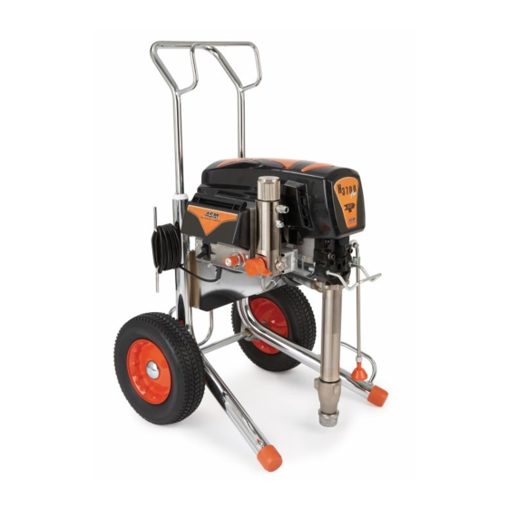
H3700 Airless Sprayer
- For Portable Airless Spraying of Architectural Coatings and Paints. For professional use
only. Not for use in explosive atmospheres.-
Models 249172, 247620: 110 Vac UK
Models 249173, 247619: 240 Vac Multi-cord
Maximum Working Pressure: 3300 psi (227 bar, 22.7 MPa)
IMPORTANT SAFETY INSTRUCTIONS
Read all warnings and instructions in this
manual. Save these instructions.
310994E
EN
Advertisement
Table of Contents

Related Manuals for ASM 249172


Summary of Contents for ASM 249172
- Page 1 - For Portable Airless Spraying of Architectural Coatings and Paints. For professional use only. Not for use in explosive atmospheres.- Models 249172, 247620: 110 Vac UK Models 249173, 247619: 240 Vac Multi-cord Maximum Working Pressure: 3300 psi (227 bar, 22.7 MPa)
-
Page 2: Table Of Contents
110 Vac UK Motor Control Board ... 18 ASM Standard Warranty ....34 110 Vac U.K. -
Page 3: Warnings
Warnings Warnings The following warnings are for the setup, use, grounding, maintenance and repair of this equipment. The exclamation point symbol alerts you to a general warning and the hazard symbol refers to procedure-specific risks. Refer back to these warnings. Additional, product-specific warnings may be found throughout the body of this manual where appli- cable. - Page 4 • Check hoses and parts for signs of damage. Replace any damaged hoses or parts. • This system is capable of producing 3300 psi. Use ASM replacement parts or accessories that are rated a minimum of 3300 psi. • Always engage the trigger lock when not spraying. Verify the trigger lock is functioning properly.
- Page 5 Do not kink or over-bend the hose. • Do not expose the hose to temperatures or to pressures in excess of those specified by ASM. • Do not use the hose as a strength member to pull or lift the equipment.
-
Page 6: Component Identification And Function
Component Identification and Function Component Identification and Function Motor DC motor, permanent magnet, totally enclosed, fan cooled Drive Assembly Transfers power from DC motor to displacement pump Displacement Pump Transfers fluid to be sprayed from source through spray gun Fluid Outlet Fluid hose is connected here Prime Valve Used to prime and drain sprayer (also relieves fluid outlet pressure) when open... -
Page 7: General Repair Information
General Repair Information General Repair Information Pressure Relief Procedure NOTICE To reduce risk of pressure control malfunction: • Use needle-nose pliers to disconnect wire. System pressure must be manually relieved to pre- Never pull on wire, pull on connector. vent system from starting or spraying accidentally. •... -
Page 8: Grounding
Grounding Grounding Improper installation or alteration of grounding plug results in risk of electric shock, fire or explosion that could cause serious injury or death. 1. Ultra Max II 695, 795 and 1095 100-200 Vac models require a 50/60 Hz, 15A circuit with a grounding receptacle. -
Page 9: Troubleshooting
Troubleshooting Troubleshooting Mechanical/Fluid Flow Relieve pressure; page 7. WHAT TO CHECK WHAT TO DO TYPE OF PROBLEM If check is OK, go to next check When check is not OK, refer to this column E=XX is displayed 1. Fault condition exists 1. - Page 10 Troubleshooting WHAT TO CHECK WHAT TO DO TYPE OF PROBLEM If check is OK, go to next check When check is not OK, refer to this column Pump output is low 14. O-ring in pump is worn or dam- 14. Replace o-ring; see pump manual 310643 aged or 310894.
-
Page 11: Electrical
Troubleshooting Electrical Relieve pressure; page 7. WARNING To avoid electrical shock or moving parts hazards Symptom: Sprayer does not run or stops running. when covers are removed for troubleshooting, wait • Plug sprayer into correct voltage, grounded out- 30 seconds after unplugging power cord for stored electricity to dissipate. - Page 12 Troubleshooting TYPE OF PROBLEM WHAT TO CHECK HOW TO CHECK Sprayer does not run at all Check transducer or transducer Set sprayer to OFF and disconnect power to sprayer. connections (control board is not Digital display shows E=03 Check transducer and connections to control board. detecting a pressure signal).
- Page 13 Troubleshooting TYPE OF PROBLEM WHAT TO CHECK HOW TO CHECK Sprayer does not run at all Control is commanding motor to run Remove pump and try to run sprayer. If motor runs, but motor shaft does not rotate. check for locked or frozen pump or drive train. Digital display shows E=05 Possibly locked rotor condition, an If sprayer does not run, continue to step 2.
- Page 14 Troubleshooting TYPE OF PROBLEM WHAT TO CHECK HOW TO CHECK Sprayer does not run at all Control is commanding motor to run Perform Field Short Test: Test at large 4-pin motor but motor shaft does not rotate. field connector. There should not be continuity from Digital display shows E=05 Possibly locked rotor condition, pin 4, the ground wire, and any of the remaining...
- Page 15 Troubleshooting TYPE OF PROBLEM WHAT TO CHECK HOW TO CHECK Sprayer does not run at all Allow sprayer to cool. If sprayer runs NOTE: Motor must be cooled down for the test. when cool, correct cause of Digital display shows E=06 Check thermal device connector (yellow wires) overheating.
- Page 16 Troubleshooting Sprayer Will Not Shut Off 1. Relieve Pressure, page 7. Leave prime valve open 2. Remove control box cover so the control board and power switch OFF. status light can be viewed if available. Troubleshooting Procedure Plumb pressure gauge into paint Mechanical problem: See the proper hose, plug sprayer in, and turn power fluid pump manual for the sprayer for...
- Page 17 Troubleshooting Sprayer Will Not Run (See following page for steps) Remove control box cover. Turn sprayer ON. Observe control board status light on control board (see page 11). No light See Step 1. Do See Step 2. Do Repair or you have over you have over replace...
-
Page 18: Pressure Control Repair
Pressure Control Repair Pressure Control Repair 110 Vac UK Motor Control Board Removal Installation 1. Use Acetone or equivalent solvent to thoroughly remove thermal paste from the pockets of the Powerbar. Relieve pressure; page 7. Wait 5 minutes before servicing. 2. - Page 19 Pressure Control Repair 3. Install two screws (102), six screws (27), and 8. Connect motor control board power connectors motor control board. (K) to filter board (146). Connect filter connector (J) and power cord connector (D) to 4. Install and torque two screws (102) to values in ON/OFF switch (33).
-
Page 20: 110 Vac U.k. Filter Board
Pressure Control Repair 110 Vac U.K. Filter Board Relieve pressure; page 7. Wait 5 minutes before servicing. Removal Installation 1. Remove four screws (38) and cover (96). 1. Connect motor control board power connectors (K) to filter board (146). Connect filter 2. -
Page 21: 240 Vac Motor Control Board
Pressure Control Repair 240 Vac Motor Control Board Removal Installation 1. Use Acetone or equivalent solvent to thoroughly remove thermal paste from the pockets of the Powerbar. Relieve pressure; page 7. Wait 5 minutes before servicing. 2. Apply thermal compound: For 2 capacitor boards and 6 capacitor 1. - Page 22 Pressure Control Repair 3. Install two screws (102), six screws (27), and 7. Connect motor control board power connectors control board. (K) to filter board (146). 4. Install screws (27) and torque to the values 8. Install control box (61) with top two screws (39). shown in the diagram on page 22.
-
Page 23: 240 Vac Uk Filter Board
Pressure Control Repair 240 Vac UK Filter Board Relieve pressure; page 7. Wait 5 minutes before servicing. Removal Installation 1. Remove four screws (38) and cover (96). 1. Install filter board (146) with four screws (163). 2. Disconnect display connector (A) from motor 2. -
Page 24: Pressure Adjust Potentiometer
Pressure Control Repair Pressure Adjust Potentiometer Removal Installation 1. Install gasket (115), nut and potentiometer (82) on control panel (68). Torque nut to 30-35 in-lb (3.38 - 3.95 N•m). Relieve pressure; page 7. Wait 5 minutes before servicing. 1. Remove four screws (38) and cover (96). ti12998a 2. -
Page 25: Pressure Control Transducer
Pressure Control Repair Pressure Control Transducer Removal 4. Remove four screws (39) and control box (61). Allow control panel (68) to hang down freely. Relieve pressure; page 7. Wait 5 minutes before servicing. 1. Remove four screws (38) and cover (96). ti7458a ti13494a ti13493a... - Page 26 Pressure Control Repair Installation 1. Install o-ring (20) and transducer (86) in filter 3. Install control box (61) and control panel (68) base (67). Torque to 35-45 ft-lb (47-61 N•m). with four screws (39). Install grommet onto transducer (86) and transducer into control box.
-
Page 27: Drive And Bearing Housing Replacement
Drive and Bearing Housing Replacement Drive and Bearing Housing Replacement NOTICE Do not drop gear cluster (89) when removing drive housing (90). Gear cluster may stay engaged in motor front end bell or drive housing. Installation Removal Make sure gear (89) and thrust washers (28, 30, 90a, 36;... - Page 28 Drive and Bearing Housing Replacement ti4253c 310994E...
-
Page 29: Motor Replacement
Motor Replacement Motor Replacement Removal 8. Remove two screws (23) and nuts (19) on side opposite control. 9. Loosen two nuts (19) on side near control and remove motor (84) from frame cart (62). Relieve pressure; page 7. Installation 1. Remove pump (91); see Displacement Pump 1. - Page 30 Motor Replacement Motor Replacement 310994E...
-
Page 31: Displacement Pump Replacement
Displacement Pump Replacement Displacement Pump Replacement See pump manual 311061 for pump repair OFF and unplug power cord. Push up retaining instructions. ring (43) and push pump pin out. See manual 310929 for applicable sprayer part number references. Removal ti7168a 1. -
Page 32: Installation
Displacement Pump Replacement Installation 2. Install pump pin (44). Verify retaining spring (43) is in groove of connecting rod (85). 3. Push pump up until pump threads engage. NOTICE If pump pin works loose, parts could break off 4. Screw in pump until threads are flush with drive due to force of pumping action. -
Page 33: Technical Data
Technical Data Technical Data Generator Cycles per Maximum Fluid 220-240V, 100-120V, Minimum Motor HP gallon Delivery Maximum Outlet ø , A, Hz Model A, Hz (liter) gpm (lpm) Tip Size npsm 1 Gun 2 Guns H3700 10, 50/60 5000 2.20 (1640) 110 (29) 1.2 (4.3) 0.035 0.023... -
Page 34: Asm Standard Warranty
ASM, ASM will, for a period of twelve months from the date of sale, repair or replace any part of the equipment determined by ASM to be defective. This warranty applies only when the equipment is installed, operated and maintained in accordance with ASM’s written recommendations.
Need help?
Do you have a question about the 249172 and is the answer not in the manual?
Questions and answers