Advertisement
Quick Links
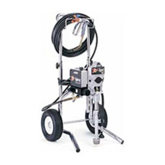
Repair Instructions and Parts List
- For portable spray application of architectural paints and coatings -
1900 Plust Airless Paint Sprayer
3000 psi (207 bar, 20.7 MPa) Maximum Working Pressure
Important Safety Instructions
Read all warnings and instructions in this manual.
Save these instructions.
ti7508a
Hi-Boy 233782
Series A, B, C, D, E, F
Parts
. . . . . . .
309427
. . . . . . .
309971
. . . . . . .
309428
Model 233782 (Series A, B)
Model 246649 (Series A, B, C, D)
. . . . . . .
311062
Model 233782 (Series C, D, E, F)
ti8027a
Stand 246649
Series A, B, C, D
309423M
Advertisement

Related Manuals for ASM Zip-Spray 1900 Plus


Summary of Contents for ASM Zip-Spray 1900 Plus
- Page 1 Repair Instructions and Parts List 309423M Parts - For portable spray application of architectural paints and coatings - 1900 Plust Airless Paint Sprayer 3000 psi (207 bar, 20.7 MPa) Maximum Working Pressure Important Safety Instructions ..309427 Read all warnings and instructions in this manual.
-
Page 2: Specifications
Specifications This equipment is not intended for use with flammable or combustible materials used in places such as cabinet shops or other “factory” or fixed locations. If you intend to use this equipment in this type of application, you must comply with NFPA 33 and OSHA requirements for the use of flammable and combustible materials. - Page 3 WARNING ELECTRIC SHOCK HAZARD Improper grounding, setup, or usage of the system can cause electric shock. D Turn off and disconnect power cord before servicing equipment. D Use only grounded electrical outlets D Use only 3--wire extension cords. D Ensure ground prongs are intact on sprayer and extension cords. D Do not expose sprayer to rain.
-
Page 4: Component Identification And Function
Component Identification and Function ti6013b ti5875b Fig. 1 309423... - Page 5 Component Identification and Function Motor DC motor, permanent magnet, fan cooled Drive Assembly Transfers power from DC motor to displacement pump Displacement Pump Transfers fluid to be sprayed from source through spray gun Fluid Outlet Spray gun is connected here Prime Valve Used to prime and drain sprayer (also relieves fluid outlet pressure) when open...
- Page 6 Grounding and Electric Requirements The sprayer must be grounded. Grounding reduces the risk of static and electric shock by providing an escape wire for the electrical cur- rent due to static build up or in the event of a short circuit. D The sprayer requires a 120V AC, 60 Hz, 15A circuit with grounding receptacle.
-
Page 7: Thermal Overload
Grounding and Electric Requirements D Ground the metal pail by clamping one end of ground wire to pail and the other end to ground, such as a water pipe. ti5851a D Maintain grounding continuity when flushing or relieving pressure by hold- ing metal part of spray gun firmly to side of a grounded metal pail, then trigger gun. -
Page 8: Pressure Relief Procedure
Pressure Relief Procedure Follow Pressure Relief Procedure when you stop spraying and before cleaning, checking, servicing or transporting equipment. 1. Turn power switch OFF and unplug power cord. 2. Turn Spray--Prime/Drain valve to PRIME/DRAIN to relieve pressure. PRIME 3. Turn pressure to lowest setting. Hold metal part of gun firmly to a grounded metal pail. -
Page 9: General Repair Information
General Repair Information WARNING To reduce risk of serious injury, including electric shock: D Do not touch moving or electric parts WARNING with fingers or tools while testing repair Flammable materials spilled on hot, D Unplug sprayer when power is not bare, motor could cause fire or required for testing explosion. - Page 10 Troubleshooting Before performing any repairs, relieve pressure, page 8. MOTOR WON’T OPERATE TYPE OF PROBLEM WHAT TO CHECK WHAT TO DO If check is OK, go to next check When check is not OK refer to this column 1. Pressure control knob setting. Motor will not run 1.
- Page 11 1. Motor control board. Board shuts down and dis- 1. See Motor Control Board Diagnostics, Basic Electrical Problems plays error code on some models. page 19. See Wiring Diagram, page , p g 2. Electrical supply. Meter must read 100--130 2.
- Page 12 Troubleshooting LOW OR FLUCTUATING OUTPUT TYPE OF PROBLEM WHAT TO CHECK WHAT TO DO If check is OK, go to next check When check is not OK refer to this column Low Output 1. For worn spray tip. 1. Follow Pressure Relief Procedure Warn- ing, then replace tip.
- Page 13 Troubleshooting LOW OR FLUCTUATING OUTPUT TYPE OF PROBLEM WHAT TO CHECK WHAT TO DO If check is OK, go to next check When check is not OK refer to this column Motor runs and pump strokes 1. Paint supply. 1. Refill and reprime pump. 2.
-
Page 14: Spin Test
Spin Test Setup Armature, Brushes, and Motor Wiring Open Circuit Test (Continuity) 1. Connect red and black motor leads together with test lead. Turn motor fan by hand at about two revolutions per second. 2. If uneven or no resistance, check for: broken brush To check armature, motor winding and brush electrical springs, brush leads, motor leads;... - Page 15 Motor Brush Replacement 6. Fig. 4. Insert brush (B). Push cap (A) into place 8. If replacement brush harness has 2 yellow wires over brush. Orient each cap with the 2 projections (C), cut, strip, and crimp the 2 yellow wires (D) on either side of the brush lead.
- Page 16 On/Off Switch Replacement Installation 1. Install new ON/OFF switch (23). Install locking ring (24) and toggle boot (25). Removal 2. Connect two wires (A) to ON/OFF switch. Relieve pressure; page 8. 2. Fig. 5. Remove four screws (18) and pressure 3.
-
Page 17: Wiring Diagram
Wiring Diagram 120 Vac (Capacitor on Motor) 233782, A ON/OFF Switch Black Power Pressure Transducer Plug TI0060 White Green Yellow from Motor Potentiometer Red (+) Black (--) Used on 233782 A only Capacitor Ref134 Ref133 (Capacitor on PC Board) 233782, B, C, D, E 246649, A, B, C ON/OFF Switch... - Page 18 Wiring Diagram Black 233782: F 246649: D White ON/OFF Black Switch Green Motor Power White Connector Cord Pressure Switch Black ti7415a Fig. 7 309423...
-
Page 19: Pressure Control Repair
Pressure Control Repair Motor Control Board Diagnostics For these Models and Series ONLY: 233782: A, B, C, D, E 246649: A, B, C Note: Keep a new transducer on hand to use for test. 1. Remove four screws (18) and cover (39). 2. -
Page 20: Motor Control Board
Pressure Control Repair Motor Control Board For these Models and Series ONLY: 233782: A, B, C, D, E 246649: A, B, C Removal Installation 1. Clean pad on rear of motor control board. Apply Refer to Fig. 5 and 6. small amount of thermal compound 073019 to pad. -
Page 21: Pressure Control Transducer
Pressure Control Repair For these Models and Series ONLY: 233782: A, B, C, D, E 246649: A, B, C Pressure Control Transducer Pressure Adjust Potentiometer Removal Removal Refer to Fig. 5 and 6. Refer to Fig. 5 and 6. 1. Relieve pressure; page 8. 1. - Page 22 Pressure Control Repair For these Models and Series ONLY: 233782: F 246649: D Motor Control Board Installation Removal 1. Assemble control board (8) with 4 screws (9). 1. Relieve pressure; page 8. 2. Connect motor connector, pressure control con- 2. Remove 4 screws (17) and control cover (16). nector, white wire to control board (8) and black wire to switch (4).
-
Page 23: Pressure Control
Pressure Control Repair For these Models and Series ONLY: 233782: F 246649: D Pressure Control Removal (See Fig. 8, page 22) Installation (See Fig. 8, Page 22) NOTE: The pressure control has been preset at the fac- tory to the design stall pressure. 1. -
Page 24: Drive Housing Replacement
Drive Housing Replacement 4. Remove two front screws (22). CAUTION 5. Remove two back screws (22). Do not drop gear cluster (7) when removing drive housing (10). Gear cluster may stay engaged in 6. Pull drive housing (10) off of motor (1). motor front end bell or drive housing. -
Page 25: Motor Replacement
Motor Replacement Disassembly 7. Remove three screws (22) behind board and remove control housing (21). 8. Remove four screws (22) and motor (1) from frame (63). 1. Relieve pressure; page 8. Assembly 2. Remove pump (13), Displacement Pump Replacement, page 26. 1. -
Page 26: Displacement Pump Replacement
Displacement Pump Replacement Removal 1. Flush pump (13). 4. Cycle pump until pump pin (9a) is in position to be removed. Remove pump pin (9a). 5. Fig. 12. Remove suction tube (78) and hose (19). 6. Loosen pump jam nut (12). Unscrew pump. 2. - Page 27 Notes 309423...
- Page 28 Parts Drawing - - Sprayer Zip Spray 1900t Plus Sprayer Model 246649, Series A PARTS, PAGE 40 Ref 19 84 Ref Ref 84 Ref 78 ti3920c 309423...
- Page 29 Parts List - - Sprayer Zip Spray 1900 Plust Sprayer Model 246649, Series A NO. PART NO. DESCRIPTION NO. PART NO. DESCRIPTION 245893† MOTOR, 120 Vac 241858 FRAME, stand mount 115525 BLADE, fan motor 195177 HOLDER, suction tube 243219 GEAR, combination 107310 PLUG, tubing 243218...
- Page 30 Parts Drawing - - Sprayer Zip Spray 1900 Plust Sprayer Model 246649, Series B, C Ref 19 PARTS, PAGE 40 84 Ref Ref 84 Ref 78 ti6017b 309423...
- Page 31 Parts List - - Sprayer Zip Spray 1900 Plust Sprayer Model 246649, Series B, C NO. PART NO. DESCRIPTION NO. PART NO. DESCRIPTION MOTOR, 120 Vac 241858 FRAME, stand mount 245893† 246649, B 195177 HOLDER, suction tube 249610† 246649, C 107310 PLUG, tubing 115525...
- Page 32 Parts Drawing - - Sprayer Zip Spray 1900 Plust Sprayer Model 246649, Series D PARTS, PAGE 41 Ref 19 84 Ref Ref 84 Ref 78 ti7411b 309423...
- Page 33 Parts List - - Sprayer Zip Spray 1900 Plust Sprayer Model 246649, Series D NO. PART NO. DESCRIPTION NO. PART NO. DESCRIPTION 249826‡ KIT, MOTOR, 120 vac 107310 PLUG, tubing 249947† KIT, repair, fan 115506 SCREW, slot hd, hex, washer hd 243219 GEAR, combination 195425...
- Page 34 Parts Drawing - - Sprayer Zip Spray 1900 Sprayer Model 233782, Series A & B * Parts 130 through 134 not used on later models. See Parts List - - Sprayer, page 33. 130* 131* ti3921b 132* 133* 134* PARTS, PAGE 40 309423...
- Page 35 Parts List - - Sprayer Zip Spray 1900 Sprayer Model 233782, Series A & B NO. PART NO. DESCRIPTION NO. PART NO. DESCRIPTION KIT, MOTOR, 120 Vac 107310 PLUG, tubing 242009† 233782, A 241938 HANDLE, cart 245893† 233782, B 106062 WHEEL, semi--pneumatic 115525 BLADE, fan motor...
- Page 36 Parts Drawing - - Sprayer Zip Spray 1900 Sprayer Model 233782, Series C, D, E (Series C shown) ti7031b PARTS, PAGE 40 309423...
- Page 37 Parts List - - Sprayer Zip Spray 1900 Sprayer Model 233782, Series C, D, E NO. PART NO. DESCRIPTION NO. PART NO. DESCRIPTION KIT, MOTOR, 120 Vac 119451 WHEEL, semi--pneumatic 245893† 233782; C, D 115480 KNOB, t--handle 249610† 233782; E 105521 PLUG, tubing 115525...
- Page 38 Parts Drawing Zip Spray 1900 Sprayer Model 233782, Series F ti7413b PARTS, PAGE 41 309423...
- Page 39 Parts List Zip Spray 1900 Sprayer Model 233782, Series F NO. PART NO. DESCRIPTION NO. PART NO. DESCRIPTION 249826‡ KIT, MOTOR, 120 vac 241938 HANDLE, cart 249947† BLADE, fan motor 119451 WHEEL, semi--pneumatic 243219 GEAR, combination 115480 KNOB, t--handle 243218 CRANK SHAFT 105521 PLUG, tubing...
- Page 40 Parts Drawing - - Sprayer Ref 1 ti6019a Ref 45 Zip Spray 1900 Sprayer 233782 A, B, C, D, E 246649 A, B, C See Wiring Diagram, page 17. NO. PART NO. DESCRIPTION NO. PART NO. DESCRIPTION 115492 SCREW, slot hd, hex, washer hd BOARD, control (see page 17) 276539 HOUSING, control...
- Page 41 Parts List - - Sprayer Zip Spray 1900 Sprayer Model 233782, Series F Model 246649, Series D ti7414a See Wiring Diagram, page 18. NO. PART NO. DESCRIPTION NO. PART NO. DESCRIPTION 277210 BOX, control, 190 253117 CONTROL, pressure, 190, 120V, 115495 SCREW, mach, hex washer hd includes 15...
-
Page 42: Technical Data
Technical Data 100- -120V, ∅, A, Generator Motor HP Cycles per gallon Maximum Maximum Fluid Outlet Minimum W (liter) Delivery Tip size npsm gpm (lpm) 1, 15, 50/60 3000 7/8 (653) 680 (180) 0.38 (1.25) 0.019 1/4 in. Basic Sprayer Wetted Parts: ......zinc-plated carbon steel, polyurethane, polyethylene, stainless steel, PTFE, acetal chrome plating, leath-... - Page 43 Notes 309423...
- Page 44 ASM distributor to the original purchaser for use. With the exception of any special, extended, or limited warranty published by ASM, ASM will, for a period of twelve months from the date of sale, repair or replace any part of the equipment determined by ASM to be defective.
Need help?
Do you have a question about the Zip-Spray 1900 Plus and is the answer not in the manual?
Questions and answers