Advertisement
Quick Links
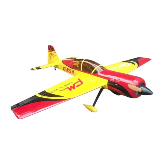
Wing Span:76.7in/1950mm;
Wing Area:71.8sq.dm;
Length:73.5in/1867.3mm;
CAUTION : this plane is not a toy!
Before use , please carefully read this manual.
●First-time builders should seek advice from people having building
experience in order to assemble the model correctly and to produce its
performance to full extent .
●Assemble this kit only in places out of children's reach!
●Take enough safety percautions prior to operating this model.
You are responsible for this model's assembly and safe operation!
●Always keep this instruction manual ready at hand for quick
reference,even after completing the assembly.
Flying Weight:4500-5100g;
Radio:6channels 6-7servos;
Engine:35-40CC GAS;
P.1
Advertisement

Related Manuals for Flight Model YAK-54 35-40CC


Summary of Contents for Flight Model YAK-54 35-40CC
- Page 1 Wing Span:76.7in/1950mm; Flying Weight:4500-5100g; Wing Area:71.8sq.dm; Radio:6channels 6-7servos; Length:73.5in/1867.3mm; Engine:35-40CC GAS; CAUTION : this plane is not a toy! Before use , please carefully read this manual. ●First-time builders should seek advice from people having building experience in order to assemble the model correctly and to produce its performance to full extent .
-
Page 2: Main Wings
MAIN WINGS Gather the wings and joiner parts as show. Install the aileron horns in place with AB glue.Align the holes in the horns .Install the servo after pulling the servo extention wire in the wing.Install the servo arm on the servo and loctitle it in place on the mount screw.Install the pushrod and control horn. - Page 3 Find out the holes in each sides of fuselage,then remove the covering.Insert the carbon joiner in place,then put on wings. ●Check to make sure you have the carbon in a right length in the wings. Plastic bolt Mounting the wings with plastic bolts on both sides.
- Page 4 RUDDER AND TAIL WHEEL ●Make sure to apply Vaseline to the rudder hinges to prevent the epoxy from getting in to the joint. ●Make sure to allow room for epoxy to penetrate the hinges. Carefully slide the rudder onto each hinge and against the trailing edge of the fin.Wipe away excess epoxy with alcohol wetted wipes.
-
Page 5: Stabilizer And Elevator
●Ensure the servo doesn't bind at center or at either end point. Drill holes in the hardwood tail wheel mount and install the blind nut through the opening in the rear of the fuse. Install the mounting screw for the tail wheel. - Page 6 Mount the elevator servo in place and pull the servo wire extension up toward the front. Bolt on tabs for ●Make sure the bolts has been stabs totally screwed into the blind nuts. Install the servo arm to the servo after making sure the elevator is level with the stab with the servo is in dead center.Tape the...
-
Page 7: Main Landing Gear
Elevator pushrod. MAIN LANDING GEAR Gather the wheels,axles and collars as shown. Install the main landing gear with the bolts provided and use blind nuts already installed and use blue Loctite on the mounting bolts. Install the main landing gear on the bottom of the fuselage. - Page 8 Permanently tighten the axle to the gear strut by wrenches. Install wheel pants with two mounting bolts. Wheel pants take a lot of abuse, mount securely! The finished photo as shown.
- Page 9 THE MOTOR INSTALLED Install the four adapter to the Install the motor to the four adapter and use screws to motor inount. lock motor and adapter. Use screws to lock cowling. The finished picture as shown. Install the propeller and aluminium spinner.
-
Page 10: Glow Engine Installation
Glow Engine Installation Measure the length of the engine from the firewall mounts to the prop thrust washer for the proper distance allowing 1/4" to 1/2" from the dege of the cowl. Move if needed. Aircraft machine belly From the exhaust muffler inserted in the position, and then from the exhaust machine belly place flat, fixed. - Page 11 CANOPY Slide the rubber backed washers on the hatch mounting bolts and insert bolts through the hatch mounting holes and into the fuse blind nuts.Tighten snugly but do not over tighten and crush the hatch or the fuse sides. CG POSITION & CONTROL THROWS P.11...
- Page 12 Finished Photo Flight Model MFG CO ADD:No.10,Fu Ning Street,Xian Xi Industrial,Chang An Town,Dong Guan City,Guang Dong Province,China Tel: +86-769-85070618 / +86-769-81627996 / +86-769-89790965 Fax: +86-769-85091868 E-mail:info@flight-model.com / flight_model@126.com Web: http://www.flight-model.com/product/eindex.asp http://flight-model.preview.alibaba.com/ P.12...
Need help?
Do you have a question about the YAK-54 35-40CC and is the answer not in the manual?
Questions and answers