
Related Manuals for Flight Model EDGE-540 50CC


Summary of Contents for Flight Model EDGE-540 50CC
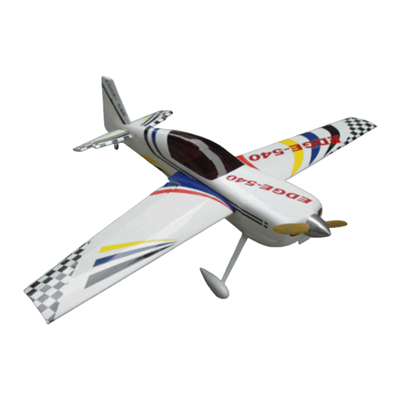
- Page 1 CAUTION:This plane is not a toy! Before use, please carefully read this manual. Wing span:84.9in/2158mm; Weight:5800g; Wing area:83.9sq.dm; Engine:50cc gas; Length:78.7in/2000mm Radio:6channels 6sevors...
- Page 2 ELEVATOR Gather the elevator, aluminium joiner and elevator parts. Connect the elevator and the aileron by hings with AB glue. Be sure to apply type AB glue to full sides of each hinges.
- Page 3 Find out and cut the holes for the servos and elevator joiner in the fuselage. Install the stablizers into the reprepared hole . Use two TP screws to fiting up the stablizers to the fuselage on each side.
- Page 4 Connect the servo wire to the extension in the fuselage. Screw the servo to the right position in the fuselage. Install the tri-horn on the right position, and fixup it with screw. Connect the tri-horn and servo with pushrod.
- Page 5 RUDDER AND TAILWHEEL Gather the rudder,tailwheel, tail landing gear and other parts together. Connect the rudder and the fuselage by hings with AB glue. Be sure to apply type AB glue to full sides of each hinges.
- Page 6 Gather the linkage parts shown below. Loop the cable back through the brass swage tube as shown. Crimp the brass tube with a criming tool or pliers.
- Page 7 Attach a metal threaded RC link to each threaded coupler. Attach the RC links to the rudder servo arm and then attach the servo arm to the rudder servo as shown. Fixup the tri-horn onto the rudder as shown.
-
Page 8: Main Wings
MAIN WINGS Gather the carbon joiner,main wings and other parts. Apply AB glue to all sides of each hinges, to connect the aileron. - Page 9 Install the servo into the fuselage and pull out the servo wire from the hole shown. Install the tri-horn on the right position, and fixup it with screw. Connect the tri-horn and servo with pushrod. shown. Find out the drilled holes on the fuselage as shown.
- Page 10 Screw the wings to the fuselage as shown. The canopy as shown. Fixup the canopy to the fuselage with TP screw.
- Page 11 LANDING GERA Wheel mounted on center of the axle. Install the wheel cover in the right position. Tighten the axle so it does not ratate during final tightening.Install wheel pants with two mounting bolts.
-
Page 12: Install The Engine
Bolt landing gear strut to fuselage with 4 screw. Ensure tapered edge of the gear strut is facing toward the rear. INSTALL THE ENGINE Line up the template with the firewall thrust lines and mark the location of the engine mounting holes. Use a 1/4 drill to dill the engine mounting holes. - Page 13 Gather the engine and mounting hardware as shown. Use a drop of blue lock tite on the engine mounting bolts prior to installing . Insert the bolts through flat fenderwashers.the firewall and into the engine stand offs.Tighten firmly.
- Page 14 Be sure to use flat fender washers on the back side of the firewall to distribute bolt pressure. Use a 1/4 bit to drill a pushrod exit hole in the firewall in line with the engine carburetor throttle arm. Attach the 2-56 ball link to the throttle pushrod and secure to the carbnretor throttle arm with a...
- Page 15 INSTALL THE COWLING Fix up the cowling with two TP screws on each sides. CG POSITION & CONTROL THROWS 130MM 130MM 5.12in Surface Throws Aileron 20 degrees Common flying Elevator 20 degrees Rudder 30 degrees Aileron 40 degrees 3D flying Elevator 40 degrees Rudder 45 degrees...
Need help?
Do you have a question about the EDGE-540 50CC and is the answer not in the manual?
Questions and answers