Advertisement
Quick Links
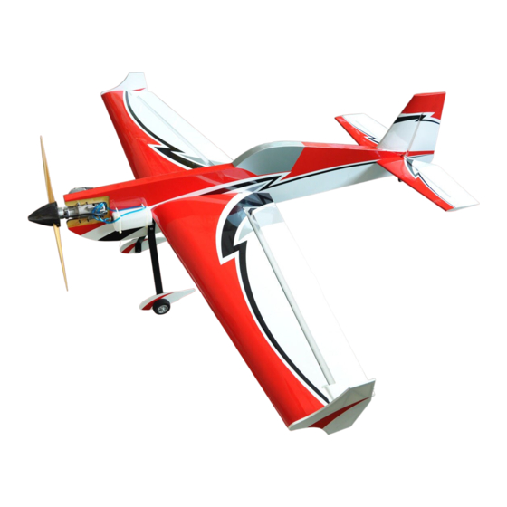
Assembly Manljal
F115 Extra 330SC 20cc profile
CAUTION : this plane is not a toy and should be kept away
children under 16 years of age! Before use , please carefully read
this manual.
●First-time builders should seek advice from people having building
experience in order to assemble the model correctly and to produce its
performance to full extent .
●Assemble this kit only in places out of children's reach!
●Take enough safety percautions prior to operating this model.
You are responsible for this model's assembly and safe operation!
●Always keep this instruction manual ready at hand for quick
reference,even after completing the assembly.
Thanks for purchasing our airplane model!
F114 Sbach 342
20cc Profile
F113 YAK 54
20CC profile
Advertisement

Related Manuals for Flight Model F113 YAK 54 20CC profile


Summary of Contents for Flight Model F113 YAK 54 20CC profile
- Page 1 Assembly Manljal F114 Sbach 342 20cc Profile F113 YAK 54 20CC profile F115 Extra 330SC 20cc profile CAUTION : this plane is not a toy and should be kept away children under 16 years of age! Before use , please carefully read this manual.
- Page 3 All the parts together Main Landing Gear and Tail Wheel Unit 1.Cut out the holes on the fuselage of both sides. 2.Gather the parts for the main landing gear.
- Page 4 3.Use screw to connect the landing gear, wheel pant, nut and wheelin turn, and finally use a lock nut to lock them. 4.Repeat the same on the other side of the landing gear. 5.Use two screws to lock the two pieces of the landing gear to the fuselage...
- Page 5 6.Drill a 6mm hole at the back tail of the fuselage to install the tail wheel...
- Page 6 7.Put the tail wheel set into the hole, and use two pcs self-tappingscrew to lock the tail wheel onto the fuselage tail. Fuel Tank and Engine lnstallation 1.Cut out the holes for the fuselage 2.Install the fuel tank and the fuel tubes as shown.
- Page 7 3.Fasten the fuel tank onto the fuselage as shown. Standard fuel tee (built-in filter) 4.finished photo.
- Page 8 5.Screw the throttle servo onto the fuselage. Bent the pushrod, and use it to connect the servo and the engine. Main Wings Installation Parts for the main wings 1.Cut out the holes in the wings...
- Page 9 2. Find out the slots for the aluminum sheet. 3.Use screw to lock the aluminum sheet onto the wings. 4.Repeat the same way on the other side of the wing.
- Page 10 5.Stick a velcro tie into the holes in the back of the wing as shown. 6. Stick the battery onto the white velcro tie. 7. Find out the cover plate of this hole...
- Page 11 8. Fix the plate onto the back of the wing by screws. Repeat the same on the other side of the wing to install the receiver. Install the winglet as shown...
- Page 12 Tail Part Installation 1.Use AB glue to glue it into the fuselage. 2.Cut out the holes on the fuselage of both sides. 3.Gather the parts for the main landing gear.
- Page 13 4.Remove the covering film at the postion for the stabilizer. 5.Use a saw to cut off the part at the end of the fuselage.
- Page 14 6.Insert the fiberglass control horn sheet into the aileron hole pre-cutted.Use AB glue to glue it. 7. Screw the servo with 4 pieces self-tapping screw. 8.Install the ball links onto the servo arm and the control horn with stainless push rod supplied.
- Page 15 9.Insert the fiberglass control horn into the elevater, and glue with AB glue Screw the elevater servo onto the fuselage as shown. 10.Connect the control horn and elevater servo with ball links and pushrod.
- Page 16 1.Cut out the slot for the rudder control horn as shown. 2.Cut out the holes in on the other side of the fuselange forthe rudder servo. 3.Insert the fiberglass control horn into the rudder, and glue with AB glue Screw the rudder servo onto the fuselage as shown.
- Page 17 4.Connect the control horn and rudder servo with ball links and pushrod. THE FINISHED PHOTO...
Need help?
Do you have a question about the F113 YAK 54 20CC profile and is the answer not in the manual?
Questions and answers