
Related Manuals for ACME CP-18TC


Summary of Contents for ACME CP-18TC
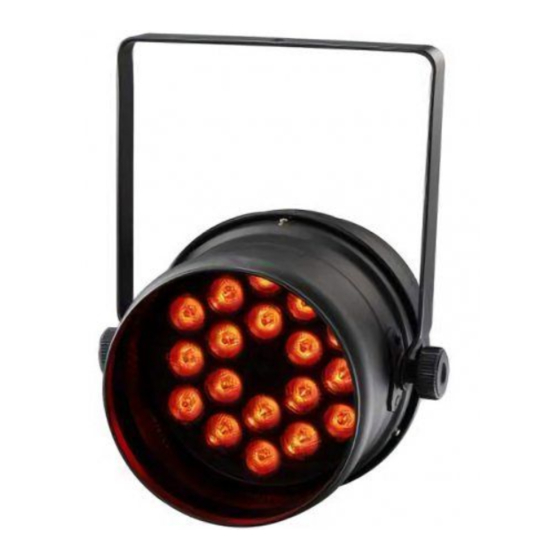
- Page 1 STAGE TRI-PAR 18TC CP-18TC User Manual Please read the instructions carefully before use...
-
Page 2: Table Of Contents
TABLE OF CONTENTS 1. Safety Instructions 2. Technical Specifications 3. How to Set the Fixture 4. How to Control the Fixture 5. DMX 512 Configuration 6. DMX 512 Connections 7. Troubleshooting 8. Fixture Cleaning... - Page 3 1. Safety Introductions Please read the instructions carefully which includes important information about the installation, operation and maintenance. WARNING Please keep this User Guide for future consultation. If you sell the unit to another user, be sure that they also receive this instruction booklet. ...
- Page 4 Do not allow children to operate the fixture. Do not touch any wire during operation as there might be a hazard of electric shock. Avoid power wires together around other cables. Disconnect mains power before fuse/lamp replacement or servicing. ...
-
Page 5: Technical Specifications
2. Technical Specifications Voltage:100-240V~ 50/60Hz LED: 18 x 3W RGB(Tri-color)LED Fuse: T 6.3A Power consumption:69W Dimension:224 x290 x362 mm Weight: 2.7 kg 3. How to Set the Fixture 3.1 Control Panel ○ 1 Display: To show the various menus and the selected functions ○... - Page 6 ○ 3 Button: MENU To select the programming functions DOWN To go backward in the selected functions To go forward in the selected functions ENTER To confirm the selected functions ○ 4 Only for remote control: Connecting with CA-8/CA-9/CA-9RTX to control the unit for Stand by, Function and Mode function.
-
Page 7: Software Version
Auto Setting DMX512 Address Show 0-12 Chase MENU Slave Mode 1-16 Sound Mode on Sound Mode off Blackout Mode " Yes Blackout " Blackout Mode " No Blackout " Color Macro LED on LED off Normal Inversion Temperature Fixture Hours Software Version... - Page 8 DMX 512 Address Setting Press the MENU button up to when the is shown on the display. Pressing ENTER button and the display will blink. Use DOWN and UP button to change the DMX 512 address. Once the address has been selected, press ENTER button to setup or automatically exit menu mode without any change after one minute.
- Page 9 functions without any change press the MENU button. Slave Mode Press the MENU button up to when the is showing on the display. Pressing ENTER button and the display will blink. Use DOWN and UP button to select the (slave 2) or … or (normal) or (16 light show) mode.
- Page 10 LED display Press the MENU button up to when the is shown on the display. Pressing ENTER button and the display will blink. Use DOWN and UP button to select (display always on) or (display off 20 seconds after exit menu) mode. Once select, press ENTER button to setup or exit menu mode without any change after one minute.
- Page 11 the functions press the MENU button again. 4. How to Control the Unit You can operate the unit in three ways: 1. By master/slave built-in preprogram function 2. By easy controller 3. By DMX controller No need to turn the unit off when you change the DMX address, as new DMX address setting will be effected at once.
- Page 12 Blackout To blackout all the fixture Function Strobe Select Color Select show Select Chase 1. Synchronous strobe in white color Color 1-16 or Show 1-12 Chase 1-16 or fade 2. The same color chase manual setting 3. Different color strobe color Mode Sound 1...
- Page 13 5. DMX512 Configuration Mode 1&2; DMX512 Configuration Mode1 Mode2 CH 1 CH 1 Green Blue Green Blue Dimmer/Strobe Dimmer Open 248-255 Fast 201-247 Slow Sound 191-200 8-190 Mode 3&4: DMX512 Configuration Mode3 Mode4 CH 1 CH 1 Green Blue Green Blue Dimmer/Strobe Dimmer...
-
Page 14: Dmx 512 Configuration
Mode 5: DMX512 Configuration Mode5 CH 1 Green Blue Dimmer Color Strobe 248-255 Color32 241-247 Color31 233-240 Color30 225-232 Color29 217-224 Color28 Open 248-255 210-216 Color27 202-209 Color26 Random strobe 240-247 194-201 Color25 Open 186-193 Color24 232-239 179-185 Color23 171-178 Color22 Slow Close 191-231 163-170 Color21... -
Page 15: Troubleshooting
Connect the fixture together in a “daisy chain” by XLR plug cable from the output of the fixture to the input of the next fixture. The cable cannot be branched or split to a “Y” cable. Inadequate or damaged cables, soldered joints or corroded connectors can easily distort the signal and shut down the system The DMX output and input connectors are pass-through to maintain the DMX circuit when one of the units’... -
Page 16: Fixture Cleaning
DMX polarity. 3. If you have intermittent DMX signal problems, check the pins on connectors or on PCB of the fixture or the previous one. 4. Try to use another DMX controller. 5. Check if the DMX cables run near or run alongside to high voltage cables that may cause damage or interference to DMX interface circuit.
Need help?
Do you have a question about the CP-18TC and is the answer not in the manual?
Questions and answers