Table of Contents
Advertisement
Quick Links
Advertisement
Table of Contents

Subscribe to Our Youtube Channel
Related Manuals for IEI Technology IOVU-430M


Summary of Contents for IEI Technology IOVU-430M
-
Page 1: User Manual
IOVU-430M Panel PC IEI Technology Corp. MODEL: IOVU-430M Panel PC, 4.3" Touch Screen, 416 MHz Marvell XScale PXA270, Fast Ethernet, USB, Mini SD, CAN bus, RS-232/422/485 RoHS Compliant, Front Panel IP 65 Protection User Manual Page i Rev. 1.01 – 6 December, 2010... - Page 2 IOVU-430M Panel PC Revision Date Version Changes 6 December, 2010 1.01 Modified system mounting method 17 September, 2010 1.00 Initial release Page ii...
- Page 3 IOVU-430M Panel PC Copyright COPYRIGHT NOTICE The information in this document is subject to change without prior notice in order to improve reliability, design and function and does not represent a commitment on the part of the manufacturer. In no event will the manufacturer be liable for direct, indirect, special, incidental, or consequential damages arising out of the use or inability to use the product or documentation, even if advised of the possibility of such damages.
-
Page 4: Table Of Contents
IOVU-430M Panel PC Table of Contents 1 INTRODUCTION......................1 1.1 O ........................2 VERVIEW 1.2 B ........................2 ENEFITS 1.3 F ........................3 EATURES 1.4 F ......................3 RONT ANEL 1.5 C ....................4 ONNECTOR ANEL 1.6 D ....................... 5 IMENSIONS 1.7 P... - Page 5 IOVU-430M Panel PC 3.5 S ........................ 23 OFTWARE 3.5.1 Wireless AP ...................... 23 A CERTIFICATIONS ....................26 A.1 R HS C ....................27 OMPLIANT A.2 IP 65 C ................27 OMPLIANT RONT ANEL B SAFETY PRECAUTIONS ..................28 B.1 S .....................
- Page 6 List of Figures Figure 1-1: IOVU-430M ........................2 Figure 1-2: Front Panel ........................3 Figure 1-3: IOVU-430M Peripheral Connectors ................4 Figure 1-4: IOVU-430M Physical Dimensions (millimeters) ............5 Figure 3-1: Mini SD Card Installation..................13 Figure 3-2: IOVU-430M Peripheral Connectors .................14 Figure 3-3: Power Terminal Block....................15 Figure 3-4: GPIO and CAN Bus Terminal Block ................16...
- Page 7 IOVU-430M Panel PC List of Tables Table 1-1: IOVU-430M Specifications ...................6 Table 1-2: Technical Specifications....................8 Table 2-1: Package List Contents ....................11 Table 2-2: Optional Items......................11 Table 3-1: External Interface Connectors...................14 Table 3-2: 12~36 V Power Connector Pinouts ................15 Table 3-3: GPIO and CAN Bus Connector Pinouts ..............16 Table 3-4: RS-232 Pinouts ......................18...
-
Page 8: Introduction
IOVU-430M Panel PC Chapter Introduction Page 1... -
Page 9: Overview
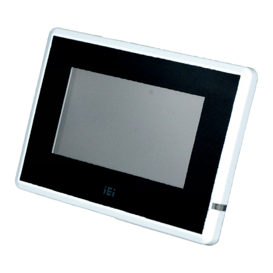
1.1 Overview Figure 1-1: IOVU-430M The IOVU-430M Panel PC comes with a 4.3" touch panel screen. It is powered by a 416 MHz Marvell XScale PXA270 processor and has 128 MB of SDRAM. The IOVU-430M includes a Mini SD card with Windows CE 5.0 installed. The package also includes a software development kit and documentation to help easily customize the operating system according to needs. -
Page 10: Features
Projected capacitor multi-touch panel or 4-wire resistive single-touch panel 12-36 VDC input RoHS compliant 1.4 Front Panel The IOVU-430M front panel (Figure 1-2) comprises a 4.3" TFT WQVGA color touch screen LCD in an ABS+PC plastic frame. Figure 1-2: Front Panel Page 3... -
Page 11: Connector Panel
1.5 Connector Panel The external peripheral interface connectors are located on the bottom and side panels of the IOVU-430M . The peripheral interface connectors are shown in Figure 1-3. Figure 1-3: IOVU-430M Peripheral Connectors External peripheral interface connectors on the IOVU-430M include:... -
Page 12: Dimensions
IOVU-430M Panel PC 1.6 Dimensions The physical dimensions of the IOVU-430M are shown in Figure 1-4 and listed below: Width: 145 mm Height: 104 mm Depth: 34 mm Figure 1-4: IOVU-430M Physical Dimensions (millimeters) Page 5... -
Page 13: Power Supply And Battery
And Risk of explosion if battery is replaced by an incorrect type. Dispose of used batteries according to the instructions The IOVU-430M has a terminal block connector on the bottom panel. 1.8 Model Variations The IOVU-430M is available in the following model variations. -
Page 14: Technical Specifications
IOVU-430M Panel PC 1.9 Technical Specifications The IOVU-430M technical specifications are listed in Table 1-2. Specifications System 416 MHz Marvell XScale PXA270 processor 2 MB boot ROM 128 MB of SDRAM Memory 1 GB Mini SD card Battery backup RTC Real-time Clock Software programmable supports 1~255 sec. -
Page 15: Certifications
IP 65 compliant front panel Ingress Protection Table 1-2: Technical Specifications 1.10 Certifications All IOVU-430M series models comply with the following international standards: RoHS IP 65 compliant front panel For a more detailed description of these standards, please refer to Appendix A. -
Page 16: Unpacking
IOVU-430M Panel PC Chapter Unpacking Page 9... -
Page 17: Anti-Static Precautions
When the IOVU-430M is unpacked, please do the following: Follow the anti-static precautions outlined in Section 2.1. Make sure the packing box is facing upwards so the IOVU-430M does not fall out of the box. Make sure all the components shown in Section 2.3 are present. -
Page 18: Unpacking Checklist
If some of the components listed in the checklist below are missing, please do not proceed with the installation. Contact the IEI reseller or vendor you purchased the IOVU-430M from or contact an IEI sales representative directly. To contact an IEI sales representative, please send an email to sales@iei.com.tw. -
Page 19: Installation
IOVU-430M Panel PC Chapter Installation Page 12... -
Page 20: Installation Precautions
IOVU-430M. 3.2 Mini SD Card Installation The IOVU-430M supports a Mini SD card. Follow the steps below to install a Mini SD card. Slide the Mini SD card into the slot. Step 1:... -
Page 21: External Peripheral Interface Connectors
IOVU-430M Panel PC 3.3 External Peripheral Interface Connectors Table 3-1 lists the external interface connectors on the IOVU-430M. Detailed descriptions of the connectors can be found following the table. Connector Type 12-36 V DC terminal block Terminal Block CAN bus... -
Page 22: 36 V Dc Terminal Block
Figure 3-3: Power Terminal Block 3.3.2 GPIO and CAN bus Connector The IOVU-430M has a GPIO (pins 1-7) and CAN bus connector (pins 8-10). The GPIO can be used to connect to external devices or peripherals. The CAN bus connector connects to a Controller-Area Network (CAN). -
Page 23: Rs-232/422/485 Serial Port
This section outlines the usage and setup of the serial port on the bottom I/O panel. 3.3.3.1 Connecting the Serial Port The IOVU-430M has one female DB-9 connector on the external peripheral interface panel for connections to serial devices. Follow the steps below to connect a serial device to the IOVU-430M. -
Page 24: Rs-232/422/485 Selection
IOVU-430M Panel PC Figure 3-5: Serial Device Connector Secure the connector. Secure the serial device connector to the external Step 2: interface by tightening the two retention screws on either side of the connector. Step 0: 3.3.3.2 RS-232/422/485 Selection To select RS-232/422/485 mode, please follow the directions below. -
Page 25: Pinouts
IOVU-430M Panel PC Select COM1 mode setting. Select the desired mode setting for Serial Port Step 2: COM1 in the drop down menu (Figure 3-6). RS-232 RS-422 RS-485 Click the Set button. Click the Set button to apply the mode setting change. -
Page 26: Usb Connector
The external USB Series "A" receptacle connector provides easier and quicker access to external USB devices. Follow the steps below to connect USB devices to the IOVU-430M. Insert a USB Series "A" plug. Insert the USB Series "A" plug of a device into Step 1: the USB Series "A"... -
Page 27: Figure 3-9: Lan Connection
Align the connectors. Align the RJ-45 connector on the LAN cable with one of Step 1: the RJ-45 connectors on the IOVU-430M. See Figure 3-9. Figure 3-9: LAN Connection Insert the LAN cable RJ-45 connector. Once aligned, gently insert the LAN Step 2: cable RJ-45 connector into the on-board RJ-45 connector. -
Page 28: In-Wall Mounting
Standards Association (VESA) compliant. IEI provides an in-wall cage to mount the IOVU-430M into a wall. To mount the IOVU-430M in a wall, please follow the steps below. Insert the four monitor mounting screws into the four screw holes on the real... -
Page 29: Figure 3-11: Chassis Support Screws
IOVU-430M Panel PC Figure 3-11: Chassis Support Screws Align the mounting screws installed in the previous step with the screw holes Step 2: (Figure 3-12) on in-wall cage. Figure 3-12: In-wall Cage Screw Holes Carefully insert the screws through the holes and gently pull the monitor Step 3: downwards until the monitor rests securely in the slotted holes. -
Page 30: Software
For information about configuring the operating system, adding remote management tools or additional software and drivers, refer to the user manuals on IEI IOVU Utility CD that came with the IOVU-430M. The IOVU includes the following software: Standard Windows®... - Page 31 IOVU-430M Panel PC around as shown below. (Figure 3-132). Figure 3-12: Wireless AP Select your Internet connection and click Connect. Step 2: The Wireless Network Properties screen appears next. (Figure 3-133). Step 3: Figure 3-13: Wireless Network Properties Page 24...
- Page 32 IOVU-430M Panel PC You must input the password into the Network key. Click OK. The soft AP Step 4: configuration is finished. (Figure 3-134). Figure 3-14: Wireless AP Connected Click the IP Information button to view the information of the Wireless AP Solo. If Step 5: the server function is enabled on the AP.
-
Page 33: A Certifications
IOVU-430M Panel PC Appendix Certifications Page 26... -
Page 34: Rohs Compliant
A.2 IP 65 Compliant Front Panel The front panel on the IOVU-430M models in the IOVU series have an ingress protection rating (IP) of 65, IP 65. The front panel is protected from dust particles and water projected by a nozzle. -
Page 35: B Safety Precautions
IOVU-430M Panel PC Appendix Safety Precautions Page 28... -
Page 36: Safety Precautions
Do not apply voltage levels that exceed the specified voltage range. Doing so may cause fire and/or an electrical shock. Electric shocks can occur if the IOVU-430M chassis is opened when the IOVU-430M is running. Do not drop or insert any objects into the ventilation openings of the IOVU-430M. -
Page 37: Anti-Static Precautions
When maintaining or cleaning the IOVU-430M, please follow the guidelines below. B.2.1 Maintenance and Cleaning Prior to cleaning any part or component of the IOVU-430M please read the details below. Except for the LCD panel, never spray or squirt liquids directly onto any other components. -
Page 38: Cleaning Tools
In such case, the product will be explicitly mentioned in the cleaning tips. Below is a list of items to use when cleaning the IOVU-430M. C loth – Although paper towels or tissues can be used, a soft, clean piece of cloth is recommended when cleaning the IOVU-430M. -
Page 39: Fcc Precautions
IOVU-430M Panel PC B.3 FCC Precautions WARNING: This equipment has been tested and found to comply with the limits for a Class A digital device, pursuant to Part 15 of the FCC Rules. These limits are designed to provide reasonable protection against harmful interference in a residential installation. -
Page 40: C Hazardous Materials Disclosure
IOVU-430M Panel PC Appendix Hazardous Materials Disclosure Page 33... -
Page 41: Hazardous Materials Disclosure Table For Ipb Products Certified As Rohs Compliant Under 2002/95/Ec Without Mercury
IOVU-430M Panel PC C.1 Hazardous Materials Disclosure Table for IPB Products Certified as RoHS Compliant Under 2002/95/EC Without Mercury The details provided in this appendix are to ensure that the product is compliant with the Peoples Republic of China (China) RoHS standards. The table below acknowledges the presences of small quantities of certain materials in the product, and is applicable to China RoHS only. - Page 42 IOVU-430M Panel PC Part Name Toxic or Hazardous Substances and Elements Lead Mercury Cadmium Hexavalent Polybrominated Polybrominated (Pb) (Hg) (Cd) Chromium Biphenyls Diphenyl (CR(VI)) (PBB) Ethers (PBDE) Housing Display Printed Circuit Board Metal Fasteners Cable Assembly Fan Assembly Power Supply...
- Page 43 IOVU-430M Panel PC 此附件旨在确保本产品符合中国 RoHS 标准。以下表格标示此产品中某有毒物质的含量符 合中国 RoHS 标准规定的限量要求。 本产品上会附有”环境友好使用期限”的标签,此期限是估算这些物质”不会有泄漏或突变”的 年限。本产品可能包含有较短的环境友好使用期限的可替换元件,像是电池或灯管,这些元 件将会单独标示出来。 部件名称 有毒有害物质或元素 铅 汞 镉 六价铬 多溴联苯 多溴二苯 醚 (Pb) (Hg) (Cd) (CR(VI)) (PBB) (PBDE) 壳体 显示 印刷电路板 金属螺帽 电缆组装 风扇组装 电力供应组装 电池 O: 表示该有毒有害物质在该部件所有物质材料中的含量均在 SJ/T11363-2006 标准规定的限量要求以下。 X: 表示该有毒有害物质至少在该部件的某一均质材料中的含量超出 SJ/T11363-2006 标准规定的限量要求。...
Need help?
Do you have a question about the IOVU-430M and is the answer not in the manual?
Questions and answers