Table of Contents
Advertisement
Quick Links
Advertisement
Table of Contents

Related Manuals for Toto Link N200RE


Summary of Contents for Toto Link N200RE
- Page 1 User Manual TOTOLINK Wireless-N Router...
-
Page 2: Table Of Contents
TABLE OF CONTENT 1. ABOUT THIS GUIDE ........................3 1.1 Navigation of the User’s Guide ......................3 2. PRODUCT OVERVIEW......................... 3 2.1 Introduction ............................3 2.2 Features ..............................3 2.3 Panel Layout ............................4 2.3.1 Front Panel ................................ 4 2.3.2 Rear Panel ................................. 5 3. - Page 3 5.3.5 MAC Authentication ............................22 5.3.6 WDS Setup ..............................22 5.3.7 WPS Setup ............................... 23 5.3.8 Advanced Setup ............................... 24 5.4 NAT/QoS ............................... 25 5.4.1 Port Forwarding ............................... 26 5.4.2 QoS .................................. 26 5.4.3 DMZ ................................27 5.5 Firewall ..............................27 5.5.1 IP/Port Filtering ...............................
-
Page 4: About This Guide
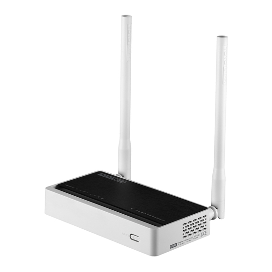
2. PRODUCT OVERVIEW 2.1 Introduction N200RE is a WLAN Router with 2 high gain antennas. It allows users to access Internet by DHCP/PPPoE/Static IP and can deliver up to 300Mbps wireless data rate. Besides, N200RE can be used as a repeater and a Wireless AP. Generally, it is a high performance and cost-effective solution for home and small offices. -
Page 5: Panel Layout
Easy to install and configure. 2.3 Panel Layout 2.3.1 Front Panel The front panel of Router N200RE consists of 8 LEDs, which is designed to indicate connection status. POWER This indicator lights blue when the router is switched on, otherwise it is off. -
Page 6: Rear Panel
2.3.2 Rear Panel The figure below shows the rear panel of the router N200RE. Power The switch allows you to power on or off the router. ON/OFF The Power socket is where you will connect the power adapter. DC IN RST: With the router powered on, press and hold the button until the CPU LED becomes quick-flash from slow-flash. -
Page 7: Hardware Installation
3. HARDWARE INSTALLATION 3.1 Hardware Installation For those computers you wish to connect with Internet by this router, each of the computers must be properly connected with the router through provided UTP LAN Cables. 1. Connect the provided UTP LAN cable to one of the router’s LAN port. 2. - Page 8 If the result displayed is similar to that shown in above figure, it means that the connection between your PC and the Router has been established. If the result displayed is similar to that shown in the above figure, it means that your PC has not connected to the Router successfully.
-
Page 9: Connecting To Internet
4. CONNECTING TO INTERNET This chapter introduces how to configure the basic functions of your router to access Internet. 4.1 Accessing Web page Connect to the Router by typing 192.168.1.1 in the address field of Web Browser. Then press Enter key. It will show up the following page that requires you to enter valid User Name and Password: Enter admin for User Name and Password, both in lower case letters. -
Page 10: Changing Password
4.2 Changing Password First, we recommend that you change the password to protect the security of your router. Please go to Management—Password change the password required to log into your Router. Old Password: the current password. New Password: new password is used for administrator authentication. Confirm Password: new password should be re-entered to verify its accuracy. -
Page 11: Internet Configuration Wizard
4.3.1 Internet Configuration Wizard This part is used to configure the parameters for Internet network which connects to the WAN port of your Access Point. There are three methods provided to allow you to access Internet. Please choose the appropriate one according to the information provided by your ISP (Internet Service Provider). -
Page 12: Pppoe (Adsl)
WAN IP: the IP address provided by your ISP. Subnet Mask: This is used to define the device IP classification for the chosen IP address range. 255.255.255.0 is a typical net mask value for Class C networks. Generally it is provided by your ISP. - Page 13 Wireless Network Name (SSID): define a name for you wireless network. Encryption: this step in fact is to set a password for your wireless network to prevent others from using your WLAN. Note: After you set the Encryption, please remember your Wireless Network Name (SSID). Then search for the SSID on your PC to build a wireless connection with the device.
-
Page 14: Advanced Settings
5. ADVANCED SETTINGS This chapter allows users to configure advanced settings includes settings for Network, Wireless, NAT/QoS Firewall and Management. These settings are only for more technically advanced users who have sufficient knowledge about wireless LAN. Also they should not be changed unless you know what effect the changes will have on your wireless router. -
Page 15: Network Settings
MAC Address: shows the MAC address of the LAN interface. LAN IP: displays the IP address of the LAN interface. Subnet Mask: shows the subnet mask address of the LAN interface. DHCP Server: displays the current status of DHCP server of the LAN interface. DHCP IP Pool: the IP address range that the DHCP server can assign to every PC connected to this device. -
Page 16: Wan Setup
5.2.3 WAN Setup This page is used to configure the parameters for the WAN port of your Access Point. Since we have discussed this setting on Easy Setup, here we introduce the MTU value. MTU: It means Max Transmit Unit for packet. When using slow links, large packets can cause some delays thereby increasing lag and latency. -
Page 17: Lan
5.2.4.1 LAN IP Address: This is the IP addresses to be represented by the LAN (including WLAN) interface that is connected to the internal network. This IP will be used for the routing of the internal network (it will be the Gateway IP for all the devices connected on the internal network). - Page 18 means that all the computers connected to this router will get IP address dynamically. Start of IP Pool IP Address: displays the start IP Address of the range that will be assigned to each computer connected with the router. End of IP Pool IP Address: displays the ending IP Address of the range that will be assigned to each computer connected with the router.
-
Page 19: Wireless
5.3 Wireless 5.3.1 Wireless Status This page displays the current wireless status of the router. 5.3.2 Wireless Basic Settings On this page, you could configure the parameters for Wireless LAN clients that may connect to your Access Point. -
Page 20: Wep
Mode: This option allows you to choose the radio standard for operation of your Router. 802.11b and 802.11g are old 2.4GHz mode, while 802.11n is the latest standard based on faster Orthogonal Frequency Division Multiplexing (OFDM) modulation. Here, by default, the B, G, N Mode is selected, this mode offers better compatibility. -
Page 21: Wpa/Wpa2
Authentication: One of the following authentication modes should be selected if WEP security method is used: Open System—station is authenticated automatically by AP. Shared Key—station is authenticated after the challenge, generated by AP. Encryption: 64-bit (selected by default) or 128-bit WEP Key length should be selected. The 128-bit option will provide a bit higher level of wireless security. -
Page 22: Repeater Setup
Encryption key: This is a pre-defined key used for encryption during data transmission. It has two formats: Passphrase and Hex (64 characters). Then you need to enter the Pre-Shared Key, either 8~63 ASCII characters, such as 012345678 (or 64 Hexadecimal digits leading by 0x, such as “0x321253abcde…”). -
Page 23: Multiple Aps
5.3.4 Multiple APs Wireless Network Name (SSID): define one more SSID for your WLAN. SSID Broadcast: choose to enable or disable this function. Authentication: please choose one encryption method for this SSID. Encryption: please refer to Wireless Basic Settings. 5.3.5 MAC Authentication You can control the number of PCs to connect with the wireless Router through MAC authentication 5.3.6 WDS Setup... -
Page 24: Wps Setup
WDS. 5.3.7 WPS Setup WPS (Wi-Fi Protected Setup) provides easy procedure to make network connection between wireless station and wireless access point with the encryption of WPA and WPA2. Pin Number: if you choose to configure WPS by PIN, then set the Pin number here. PBC: you can choose this option as well. -
Page 25: Advanced Setup
5.3.8 Advanced Setup BG Protection Mode: Background Protection Mode, by default, it is Auto selected. Basic Data Rates: you can choose the wireless data rate. This router provides three options. Be default, it is Default (1-2-5.5-11Mbps). Beacon Interval: By default, it is set to 100ms. Higher Beacon interval will improve the device’s wireless performance and is also power-saving for client side. -
Page 26: Nat/Qos
node wants to transmit is larger than the threshold, the RTS/CTS handshake gets triggered. If the packet size is equal to or less than threshold the data frame gets sent immediately. System uses Request to Send/Clear to send frames for the handshake that provide collision reduction for an access point with hidden stations. -
Page 27: Port Forwarding
5.4.1 Port Forwarding You could choose to enable or disable this function according to your requirement. Comment: please enter the reason for this port forwarding action. LAN IP: the IP of the host that is connected to the internal network and needs to be accessible form external network. -
Page 28: Dmz
Up/Down: set the bandwidth for these IP addresses. QoS List: this form shows you the QoS rule. 5.4.3 DMZ DMZ means Demilitarized Zone. It can be enabled and used as a place where services can be placed such as Web Servers, Proxy Servers and E-mail Servers such that these services can still serve the local network and are at the same time isolated from it for additional security. -
Page 29: Mac Filtering
You can select to enable or disable IP/Port Filtering function. By default, it is disabled. IP Address: the IP address range that you want to filter. Port: the Port address that you want to filter. Protocol Type: choose which particular protocol type should be filtered. Here you can choose UDP/TCP. -
Page 30: Url Filtering
MAC Filter List: this table will list the detailed information about the MAC addresses that will be filtered. 5.5.3 URL Filtering This page is used to deny LAN users from accessing the internet. Block those URLs which contain keywords listed. You can choose to enable or disable URL filtering function. -
Page 31: Internet Access Control
5.5.4 Internet Access Control First, you can choose to enable or disable this function according to your needs. Comment: Enter the name of the router. Action: you could choose to allow or deny the following addresses entered by you. Source: select the interface of the address, and enter the starting IP address that you want to deny or allow. -
Page 32: Management
5.6 Management 5.6.1 System Log This page can be used to set remote log server and show the system log. - Page 33 Click Log Setup button, it will display the page below: Remote Syslog Server/IP Address: enter an IP address that allows syslog remote sending function while System log messages are sent to a remote server. SMTP Server/IP: enter a SMTP Server address. Email Address: enter an Email address.
-
Page 34: Ddns
5.6.2 DDNS DDNS means Dynamic Domain Name System. The ISP often provides you with a dynamic IP address when you connect to the Internet via your ISP. It means that the public IP address assigned to your router changes each time you access the Internet. The Dynamic DNS feature lets you assign a domain name to a dynamic WAN IP address. -
Page 35: Upgrade Firmware
Local Time: it shows the current time by default. Enable NTP: NTP means Network Time Protocol which is used to make the computer time synchronized with its server or clock source, such as Quartz and GPS. It can provide high-precision time correction and prevent harmful protocol attack by confirming encryption. You need to check this box to activate this page. -
Page 36: Remote Management
Config Backup: click this button to save current settings to your local computer. Choose File: if you want to reload the settings from the file saved before, you could click Choose File button to choose the right file. Config Restore: you will be asked whether to restore your configuration using saved file before. -
Page 37: Reboot
regularly. You have to enable NTP in Time Zone Settings part before setting schedule. You can setup the time by which the Reboot schedule or wifi schedule works. Take figure 5-1 as example, the router will reboot at nine twenty on Friday. Figure 5-1 Take Figure 5-2 as example, WiFi will be on from eight twenty to eighteen twenty on weekday.
Need help?
Do you have a question about the N200RE and is the answer not in the manual?
Questions and answers