Table of Contents
Advertisement
Advertisement
Table of Contents

Related Manuals for Toto Link N300RU


Summary of Contents for Toto Link N300RU
- Page 1 User Manual TOTOLINK Wireless-N Router...
-
Page 2: Table Of Contents
TABLE OF CONTENTS 1. REVISION............................3 1.1 Revision History ............................. 3 2. ABOUT THIS GUIDE ........................4 2.1 Navigation of the User’s Guide ......................4 3. PRODUCT OVERVIEW......................... 4 3.1 Introduction ............................4 3.2 Features ..............................4 3.3 Panel Layout ............................5 3.3.1 Front Panel ................................ - Page 3 6.3.5 WPS ................................. 21 6.3.6 Bridge Setting ..............................22 6.3.6.1 Repeater Bridge ............................22 6.3.6.2 Repeater WAN ............................22 6.3.6.3 WDS Mode ............................... 23 6.3.7 Advanced Setting ............................. 24 6.4 QoS ................................ 25 6.5 Firewall ..............................26 6.5.1 System Firewall ............................... 27 6.5.2 IP/Port Filtering ...............................
-
Page 4: Revision
1. REVISION 1.1 Revision History Version Amendments Revision Date V1.0 Preliminary Document 2013-06-05 V1.1 Modify USB Storage Part 2013-08-31 V1.2 Add Schedule in Management section 2013-11-12... -
Page 5: About This Guide
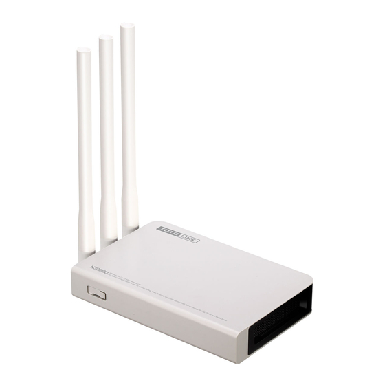
3. PRODUCT OVERVIEW 3.1 Introduction N300RU is a Wireless Router with three high gain antennas and one USB2.0 port. It offers five methods to access Internet DHCP/PPPoE/Static IP/L2TP/PPTP and can deliver up to 300Mbps wireless data rate. Besides, N300RU can be used as repeater and wireless AP. -
Page 6: Panel Layout
3.3 Panel Layout 3.3.1 Front Panel The front panel of N300RU consists of 9 LEDs, which is designed to indicate connection status. This indicator keeps solid blue when the hub is receiving power, otherwise it POWER is off. This indicator keeps lighting blue when Router powered on. -
Page 7: Rear Panel
3.3.2 Rear Panel The figure below shows the rear panel of N300RU. DC IN The Power socket is used to connect power adapter. RST: With the router powered on, press and hold the button for about 10 seconds, the router will reboot to factory default settings. -
Page 8: Antenna Placement
3.3.3 Antenna Placement To avoid signal interference and optimize antenna’s performance, you should place the antennas at an angle against the horizontal line and let antennas not be too close to each others. We recommend you orient the antennas as the following illustration shows:... -
Page 9: Hardware Installation
4. HARDWARE INSTALLATION 4.1 Hardware Installation For those PCs you wish to access Internet by this router, each of them must be properly connected through UTP cables. 1. Connect your PC’s LAN port to one of the router’s LAN port using UTP cable. 2. - Page 10 If the result displayed is similar to that shown in above figure, it means that the connection between your PC and the Router has been established. If the result displayed is similar to that shown in the above figure, it means that your PC has not connected to the Router successfully.
-
Page 11: Connecting To Internet
5. CONNECTING TO INTERNET This chapter introduces how to configure the basic functions of your router to access Internet. 5.1 Accessing Web page Connect to the Router by typing 192.168.1.1 in the address field of Web Browser. Then press Enter key. It will show up the following page that requires you to enter valid User Name and Password: Enter admin for User Name and Password, both in lower case letters. -
Page 12: Internet Setting
5.2.1 Internet Setting Here you can choose one WAN connection type from the following three options. 5.2.1.1 DHCP Dynamic Host Configuration Protocol (DHCP) is a local area network protocol. If you choose this mode, you will get a dynamic IP address from your ISP automatically. 5.2.1.2 Static IP If your ISP has provided a fixed IP that allows you to access Internet, please choose this option. -
Page 13: Pppoe
IP Address: the IP address provided by your ISP. Subnet Mask: This is used to define the device IP classification for the chosen IP address range. 255.255.255.0 is a typical net mask value for Class C networks. Generally it is provided by your ISP. - Page 14 PC and the router. Enable the Wireless connection on your computer, search for the SSID you have set (here is TOTOLINK N300RU) and connect to it. If you have set encryption Key, please type in the same Key to surf Internet.
-
Page 15: Advanced Settings
6. ADVANCED SETTINGS This chapter allows users to configure advanced settings includes Network, Wireless, QoS, Firewall, USB and Management. Most of these settings are only for more technically advanced users who have sufficient knowledge about wireless LAN. Also they should not be changed unless you know what effect the changes will have on your wireless router. -
Page 16: Network
Wireless Interface Configuration Wireless Status: shows the current wireless status. SSID: the name of your wireless network, it is case-sensitive BSSID: Basic SSID. Channel: the current Channel Number. Network Mode: the radio’s standard for operation of the router. Security Mode: the encryption method of this router. LAN Interface Configuration IP Address: display the IP address of the LAN interface. -
Page 17: Lan Setting
below information to you. 6.2.2 LAN Setting Local Area Network (LAN) is a group of subnets regulated and ruled by router. The design of network structure is related to what type of public IP addresses coming from your ISP. This page allows you to configure the parameters for LAN which connects to the LAN port of your Access Point. -
Page 18: Static Dhcp Setting
MAC Address: the physical address of the router. IP Address: this is the IP address to be represented by the LAN (including WLAN) interface that is connected to the internal network. This IP will be used for the routing of the internal network (it will be the Gateway IP for all the devices connected on the internal network). -
Page 19: Wireless
Static DHCP: you can choose to enable or disable this function from the drop-down list. MAC Address: choose the MAC address that you want to bind. IP Address: shows the IP address of selected MAC address. 6.3 Wireless The general wireless settings, such as 802.11 modes, SSID and data rates can be configured in this section. -
Page 20: Wep
Disable Wireless: you can check this box to disable wireless function. Network Mode: in fact, this option allows you to choose the radio standard for operation of your Router. 802.11b and 802.11g are old 2.4GHz mode, while 802.11n (2.4GHz and/or 5GHz) is the latest standard based on faster Orthogonal Frequency Division Multiplexing (OFDM) modulation. -
Page 21: Wpa/Wpa2-Psk (Recommended)
6.3.2.2 WPA/WPA2-PSK (Recommended) Wi-Fi Protected Access (WPA) is the most dominating security mechanism in industry. It is separated into two categories: WPA-personal or called WPA Pre-Share Key (WPA/PSK), and WPA-Enterprise or called WPA/802.1x. WPA2 means Wi-Fi Protected Access 2, it is the current most secure method of wireless security and required for 802.11n performance. -
Page 22: Wps
6.3.5 WPS WPS (Wi-Fi Protected Setup) provides easy procedure to make network connection between wireless station and wireless access point with the encryption of WPA and WPA2. It is enabled by default. WPS Mode: you can choose to enable/disable this function WPS Current Status: Display related system information for WPS. -
Page 23: Bridge Setting
PIN: please input the PIN code specified in wireless client you wish to connect, and click Start button. The WPS LED on the router will blink fast when WPS is in progress. It will return to normal condition after two minutes. (You need to setup WPS within two minutes) 6.3.6 Bridge Setting You can choose from Repeater Bridge, Repeater WAN and WDS. -
Page 24: Wds Mode
SSID to connect, then the PCs in your LAN will get IP address from the selected SSID. Note: Both these two repeater methods can help you to expand the wireless coverage and allow more terminals to access Internet. But since Repeater WAN need not stop DHCP Server, all PCs’ IP Addresses are assigned by the Secondary Router itself. -
Page 25: Advanced Setting
6.3.7 Advanced Setting Region: Please choose your country. BG Protection Mode: The default value is Auto. Just keep the value. Beacon Interval: By default, it is set to 100ms. Higher Beacon interval will improve the device’s wireless performance and is also power-saving for client side. If this value set lower than 100ms, it will speed up the wireless client connection. -
Page 26: Qos
immediately. System uses Request to Send/Clear to send frames for the handshake that provide collision reduction for an access point with hidden stations. The stations are sending a RTS frame first while data is sent only after a handshake with an AP is completed. Stations respond with the CTS frame to the RTS, which provide clear media for the requesting station to send the data. -
Page 27: Firewall
QoS: you can choose to enable this function or not. Total Uplink Speed: you can set the uplink speed for all LAN PCs. Total Downlink Speed: you can set the downlink speed for all LAN PCs. IP Address: if you choose IP address, please enter the IP address range. Uplink Bandwidth: type in the uplink bandwidth. -
Page 28: System Firewall
6.5.1 System Firewall On this page, you can disable of enable below firewall options. 6.5.2 IP/Port Filtering IP/Port Filter: you can choose to disable/enable this function. IP Address: enter the IP address that you want to filter. Protocol: specify the protocol which this filter rule will apply to. Port Range: enter the Port range that you want to filter. -
Page 29: Mac Filtering
6.5.3 MAC Filtering MAC Filter: you can choose to disable/enable this function. MAC Address: enter the MAC address that you want to filter. Comment: describe the reason why you want to filter these ports. Just few words are saved there usually. 6.5.4 URL Filtering This page is used to deny LAN users from accessing certain sites. -
Page 30: Upnp Setting
6.5.5 UPnP Setting The UPnP (Universal Plug and play) protocol is supported to bring to network connected devices the ease of installation and configuration which is already available for directly connected PC peripherals with the existing Windows “Plug and Play” system. You can enable this function so that the router doesn’t need to work out which port need to be opened. -
Page 31: Dmz Setting
Port Range: enter the port range that you want to forward. Protocol: specify the protocol which this filter rule will apply to. Comment: describe the reason why you want to filter these MAC address. Just few words are saved there usually. Current Port Forwarding List: this table will list the detailed information about the ports that will be forwarded. -
Page 32: Install Printer Driver
Before you use this function, please make sure: 1. All the computers connected to this router have installed printer driver. If not, please install it first. 2. Your printer must be an USB printer that can be connected to the router. If the two steps are ready, please choose Enable and then click Apply button to share the printer service connected to the USB port of router. - Page 33 2. Click Add a printer on the left: 3. Click Next while it comes out the welcome interface as below.
- Page 34 4. Choose “Local printer attached to this computer” and click Next. 5. Select “Create a new port” and choose “Standard TCP/IP Port” for type of port. Click Next.
- Page 35 6. Please click Next on below window. 7. The most important: please type in the gateway of your wireless router, by default, it is 192.168.1.1 for TOTOLINK wireless router. 8. Now you have to select the right Printer Manufacturer and model number and install it. Note: Make sure the Printer has been plugged into the USB port of router, else it will show you that there isn’t any printer founded.
-
Page 36: Ftp Server
9. After installation, you can share the USB Printer connected to your router. If you don’t want to share your Pinter any more, just choose Disable and click Apply to save the setting. 6.6.2 FTP Server If you enable this function, please enter the available FTP Server Name and FTP Port. FTP Function: you can choose to enable or disable FTP Server. -
Page 37: Traffic Statistics
6.7.1 Traffic Statistics This page shows the packet counters for transmission and reception regarding to wireless and Ethernet networks. 6.7.2 DDNS Setting Dynamic Domain Name System is also called DDNS simply. The ISP often provides you with a dynamic IP address when you connect to the Internet via your ISP. It means that the public IP address assigned to your router changes each time you access the Internet. -
Page 38: Ntp Setting
You could choose to enable or disable DDNS function. If you enable DDNS, you need to provide below information: Service Provider: choose one service provider where you have applied for free DDNS service. Domain Name: type in the host name you registered from the DDNS provider. User Name: enter the User Name you registered from the DDNS provider. -
Page 39: System Log
6.7.5 System Log This page can be used to set remote log server and show the system log. 6.7.6 Upgrade Firmware This page allows you to upgrade the Access Point firmware to new version. Please note: DO NOT power off the device during the upload because it may crash the system. Firmware Version: shows the current firmware version. -
Page 40: Administrator Setup
Save config file: click Save button to download the current settings of the Access Point to your computer. Update config file: if you want to reload the settings from the file saved before, you could click Choose File button to choose the right file then click Update button. Load factory default: this Restore to Factory button is provided to allow you to restore the router settings to the default factory settings. - Page 41 regularly. Reboot Schedule: you can enable or disable the reboot schedule function. Time: enter the Time Start and the router will reboot automatically by the time. Week: select the date when the schedule function operates. Wifi ON Schedule: you can enable or disable the reboot schedule function. Time Start: by the time, WiFi will turn on.
Need help?
Do you have a question about the N300RU and is the answer not in the manual?
Questions and answers