Table of Contents
Advertisement
[1]
SPECIFICATION.................................... . ....... 1-1
[2]
EXTERNAL DIMENSION....................... . ....... 1-3
[3]
WIRING DIAGRAM ................................ . ....... 1-4
[4]
ELECTRICAL PARTS ............................ . ....... 1-5
[1]
[1]
FUNCTION............................................. . ....... 3-1
[2]
TEST MODE .......................................... . ....... 3-5
[3]
DIAGNOSIS PROCEDURE ................... . ....... 3-6
Parts marked with "
" are important for maintaining the safety of the set. Be sure to replace these parts with specified ones for
maintaining the safety and performance of the set.
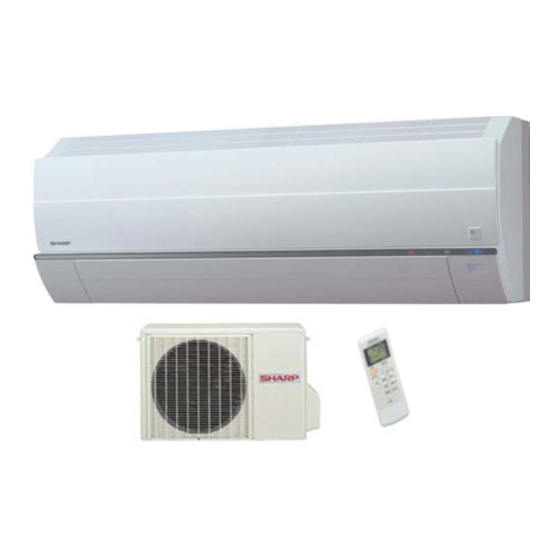
SERVICE MANUAL
SPLIT SYSTEM
ROOM AIR CONDITIONER
MODELS
CONTENTS
........ 2-1
SHARP CORPORATION
INDOOR UNIT
AY-AP7FHR
AY-AP9FHR
In the interests of user-safety (Required by safety regulations in some countries) the
set should be restored to its original condition and only parts identical to those specified
should be used.
[1]
TROUBLESHOOTING GUIDE OF CON-
TROL CIRCUIT .............................................4-1
FORMANCE CURVES
[1]
REFRIGERATION CYCLE ............................5-1
[2]
PERFORMANCE CURVES...........................5-2
[1]
INDOOR UNIT...............................................6-1
[2]
OUTDOOR UNIT...........................................6-5
This document has been published to be used
for after sales service only.
The contents are subject to change without notice.
AYAP7FHR
S8525AYAP7FHRT
OUTDOOR UNIT
AE-A7FHR
AE-A9FHR
Advertisement
Table of Contents

Related Manuals for Sharp AY-AP7FHR


Summary of Contents for Sharp AY-AP7FHR
-
Page 1: Table Of Contents
SPLIT SYSTEM ROOM AIR CONDITIONER INDOOR UNIT OUTDOOR UNIT MODELS AY-AP7FHR AE-A7FHR AY-AP9FHR AE-A9FHR In the interests of user-safety (Required by safety regulations in some countries) the set should be restored to its original condition and only parts identical to those specified should be used. -
Page 2: Chapter 1. Product Specification
AYAP7FHR AYAP7FHR Service Manual CHAPTER 1. PRODUCT SPECIFICATION [1] SPECIFICATION 1. AY-AP7FHR—AE-A7FHR INDOOR UNIT OUTDOOR UNIT ITEMS AY-AP7FHR AE-A7FHR ✩ 2.05 Cooling capacity Heat pump Heating capacity ✩ Liters/h Moisture removal Electrical data Phase Single Rated frequency Rated voltage range... - Page 3 AYAP7FHR 2. AY-AP9FHR—AE-A9FHR INDOOR UNIT OUTDOOR UNIT ITEMS AY-AP9FHR AE-A9FHR ✩ 2.64 Cooling capacity Heat pump Heating capacity ✩ Liters/h Moisture removal Electrical data Phase Single Rated frequency Rated voltage range 198 to 264 Rated voltage 220 - 240 ✩ Cool 3.8 - 3.5 Rated current...
-
Page 4: External Dimension
AYAP7FHR [2] EXTERNAL DIMENSION 1. Indoor unit 2. Outdoor unit 37.5 167.5 1 – 3... -
Page 5: Wiring Diagram
AYAP7FHR [3] WIRING DIAGRAM 1. Indoor unit C053 2. Outdoor unit 2.1. AE-A7FHR VALVE COIL 20μ F 400V ORANGE PURPLE C055 1 – 4... -
Page 6: Electrical Parts
AYAP7FHR 2.2. AE-A9FHR VALVE COIL 40μ F 400V ORANGE PURPLE C074 [4] ELECTRICAL PARTS 1. AY-AP7FHR, AE-A7FHR DESCRIPTION MODEL REMARKS SITE Compressor 5RS084DAA01 220 - 240V, 50Hz, 600W OUTDOOR Indoor fan motor SFS-230-22-4A 220 - 240V, 50Hz INDOOR Outdoor fan motor... -
Page 7: Chapter 2. Electric Circuit
AYAP7FHR AYAP7FHR Service Manual CHAPTER 2. ELECTRIC CIRCUIT [1] MICRO-COMPUTER CONTROL SYSTEM 1. Electronic Control Diagram 2 – 1... - Page 8 AYAP7FHR 2. Printed Wiring Diagram 2 – 2...
-
Page 9: Chapter 3. Functions
AYAP7FHR AYAP7FHR Service Manual CHAPTER 3. FUNCTIONS [1] FUNCTION 1. TEMPERATURE CONTROL CHARACTERISTIC 2. OPERATION MODES 1.1. COOL operation 2.1. COOL operation In the "COOL" mode, the thermostat circuit is controlled by four ther- The compressor turns on or off, at the thermostat lines C3 and C4. The mostat lines (C1 thru C5). - Page 10 3 minutes and if " E ", it's for 8 minutes. If the area " F ",compres- 53°C 53°C 53°C 53°C 54°C 54°C sor is not turned on. Only the inddor fan motpr is turned on 8 minutes AY-AP7FHR 49°C 52°C 49°C 52°C 50°C 53°C later for 3 minutes.
- Page 11 In cool and heat mode continuous compressor on operation is performed. In dry Current transition AY-AP7FHR AY-AP9FHR mode the operation is in dehumidifying zone. In fan only mode the 6.9A 8.4A...
-
Page 12: Auto Restart
AYAP7FHR 14. AUTOMATIC FAN SPEED 15. OUTPUTS IN EACH OPERATION MODE When the automatic fan speed is selected in cool or heat operation, the fan speed is automatically changed by the thermostat lines C1 to Outdoor Indoor Valve Mode Compressor C3 in cool operation, and H1 to H4 in heat operation. -
Page 13: Test Mode
Keep pushing the "AUX." buttons and supply the power, the system will go to the test mode. In this mode, the output of operation is switched by pushing the "AUX." button in the unit or the "OI" button in the remote controller. Normal outputs are shown in Table. 1. AY-AP7FHR 2. AY-AP9FHR... -
Page 14: Diagnosis Procedure
AYAP7FHR [3] DIAGNOSIS PROCEDURE When indoor fan motor is out of order or compressor lock occurs, the compressor, indoor fan motor, outdoor fan motor, and louver are all stopped and the operation LED(red) turns on or off syncronously with the timimg of the timer LED. When the thermistor for room temperature or pipe temperature is open or short state, the operation LED turns on or off syncrnoously with the timing of the timer LED by pushing continously for more than 5 seconds "AUX."... -
Page 15: Chapter 4. Troubleshooting
AYAP7FHR AYAP7FHR Service Manual CHAPTER 4. TROUBLESHOOTING [1] TROUBLESHOOTING GUIDE OF CONTROL CIRCUIT The machine does not function at all with remote controller and switches on the indoor unit. Using a tester, measure the measure the secondary voltage voltage between anodes of D1 of transformer. - Page 16 AYAP7FHR Fig. 1 Temperature properties of indoor thermistors The room is not cooled at all Room temperature Heat exchange thermistor TH1 thermistor TH2 or not cooled. The compressor does not operate. Thermistor Color Connector Room temperature Yellow No. 3 to 4 Heat exchange Orange No.
-
Page 17: Chapter 5. Refrigeration Cycle And Per
AYAP7FHR AYAP7FHR Service Manual CHAPTER 5. REFRIGERATION CYCLE AND PERFORMANCE CURVES [1] REFRIGERATION CYCLE 1. Refrigeration cycle 2. Standard conditions 1.1. AY-AP7FHR Cooling Heating Dry-bulb Temp. 27°C 20°C Indoor side Relative Humidity – Indoor unit Dry-bulb Temp. 35°C 7°C Outdoor side... -
Page 18: Performance Curves
NOTE: 1) Indoor fan speed : Hi 2) Vertical adjustment louver “45°”, Horizontal adjustment louver “Front” 3) Indoor air temp. : Cooling 27°C, Heating 20°C 4) Power source : 230V, 50Hz 1. AY-AP7FHR 1.1. Cooling 1.2. Heating Outside air temp.(ºC) Outside air temp.(ºC) -
Page 19: Chapter 6. Disassembling Procedure
AYAP7FHR AYAP7FHR Service Manual CHAPTER 6. DISASSEMBLING PROCEDURE CAUTION: DISCONNECT THE UNIT FROM THE POWER SUPPLY BEFORE ANY SERVICING [1] INDOOR UNIT 4) Remove the unit-to-unit wiring from the terminal board 1) Open the open panel. 2) Remove the screw fixing the cord clamp. 5) Remove 2 air filters. - Page 20 AYAP7FHR 8) Release 3 hooks out from cabinet. 12)Remove the control box cover. 9) Take down the front panel. 13)Cut the band and take out the sensor from sensor holder. 10)Remove 2 screws fixing the earth wire. 14)Cut the 2 bands fixing the wires. 11)Remove a screw fixing the control box cover.
- Page 21 AYAP7FHR 16)Remove the thermistor holder from the evaporator,push up the little 20)Remove drain joint screw. button and then draw out. PUSH FORWARD LITTLE BUTTON 17)Remove 3 screws fixing the control box. 21)Release 4 hooks fixing drain pan. 18)Take out the control box. 22)Take out the left side of the drain pan.
- Page 22 AYAP7FHR 24)Remove 2 screws fixing the cluster holder. 28)Hold up the left side of evaporator,pull out cross flow fan. 25)Release hooks of cluster holder and take out plasma cluster. 29)Remove 4 screws fixing motor cover. 26)Remove the screw fixing cross flow fan. 30)By holding up the left side of evaporator,take out fan motor with cover.
-
Page 23: Outdoor Unit
AYAP7FHR [2] OUTDOOR UNIT 3) Loose the unit-to-unit cord. 1) Loose a screw fixing the side cover. 4) Loose 6 screws fixing the top panel. • Right side view 2) Loose 2 screws fixing the terminal cover and 1 screw fixing the cord clamp. - Page 24 AYAP7FHR • Left side view 5) Loose 5 screws fixing the front panel. • Right side view • Front view • Left side view 6 – 6...
- Page 25 AYAP7FHR • Front view 8) Remove the terminal cover. 6) Cut 3 plastic bands. 9) Remove 3 terminals of compressor. 7) Remove 2 terminals. (connecting with fan condenser) 10)Loose 4 screws fixing the control box. Push this little button by finger and pull out 6 –...
- Page 26 AYAP7FHR 11)Take out the control box. 2. ASSEMBLING PROCEDURE OF COMPRESSOR COVER 1) Remove: Unlace the fastener and pull the compressor cover out from left side. [ a)→ b) ] 2) Assembly: Insert the compressor cover from left side, cover the tube and fasten.
-
Page 27: Replacement Parts List
AYAP7FHR REPLACEMENT PARTS LIST SPLIT SYSTEM ROOM AIR CONDITIONER INDOOR UNIT OUTDOOR UNIT MODELS AY-AP7FHR AE-A7FHR AY-AP9FHR AE-A9FHR CONTENTS INDOOR UNIT PARTS OUTDOOR UNIT PARTS ACCESSORY PARTS PARTPACKING PARTS(OUTDOOR UNIT) INDOOR PACKING PARTS INDEX OTHER PARTS(INDOOR UNIT) “HOW TO ORDER REPLACEMENT PARTS”... - Page 28 AYAP7FHR [1] INDOOR UNIT PARTS 2-13 2-12 2-11 2-10 2-24 2-20 2-20-2 2-20-3 2-20-1 2-20-6 2-17 2-20-5 2-20-1A 2-20-4 2-20-1B 2-18 2-20-12 2-20-11 2-20-10 2-20-14 2-19 2-20-9 2-20-8 2-20-13 2-14 2-20-7 2-22 2-22-1 2-15 1-10 2-23 2-22-4 2-22-2 2-22-3 2-22-6 2-22-5 2-21-2 2-21...
- Page 29 AYAP7FHR PRICE PART PARTS CODE DESCRIPTION RANK MARK RANK [1] INDOOR UNIT PARTS Control unit[AYAP7FHR] DPWBFA411JBKZ Control unit[AYAP9FHR] DPWBFA396JBKZ Power supply cord QACC-A305JBZZ QTANZA027JBZZ Terminal board QW-VZE874JBZZ Earth lead RTHM-A300JBE0 Thermistor QTANZA022JBZZ Terminal board 1-10 FPWBFA586JBKZ Display c-b-u k CHLD-A067JBK0 Bearing ass'y NFANCA099JBEZ Cross flow fan...
- Page 30 AYAP7FHR [2] ACCESSORY PARTS 4-10 PRICE PART PARTS CODE DESCRIPTION RANK MARK RANK [2] ACCESSORY PARTS CRMC-A665JBEZ Remote control UBATUA027JBE0 Battery pack LHLD-A721JBFA Cord holder Special nut LX-NZA207JBEZ EU energy label[AYAP7FHR] TLAB-C800JBEZ EU energy label[AYAP9FHR] TLAB-C801JBEZ Operation manual TINSEA406JBRZ Installation manual TINS-A876JBRZ 4-10 Drain joint...
- Page 31 AYAP7FHR [5] OUTDOOR UNIT PARTS 1-14 1-18 1-19 1-24 1-29 1-14 1-25 1-16 1-15 1-20 3-13 1-17 1-22 1-23 1-10 1-11 3-10 3-11 3-12 3-1-1 1-27 3-1-3 3-1-2 1-12 1-21 1-13 3-14 3-15 1-21 1-28...
- Page 32 PSEL-C835JBEZ Seal[AEA9FHR] 1-24 PSEL-C870JBEZ Seal 1-25 PSEL-C871JBEZ Seal 1-27 PSPF-A941JBEZ Compressor cover[AEA7FHR] 1-27 Compressor cover[AEA9FHR] PSPF-A946JBEZ 1-28 Sharp badge TLABBA149JBRZ 1-29 Name badge[AEA7FHR] TSPC-F038JBRZ 1-29 Name badge[AEA9FHR] TSPC-F057JBRZ Capacitor clamp LBNDKA062JBW0 Control box PBOX-A447JBPZ QTANZA027JBZZ Terminal board QW-IZA082JBZZ Comp wiring[AEA7FHR]...
- Page 33 AYAP7FHR [6] PARTPACKING PARTS(OUTDOOR UNIT) i d e PRICE PART PARTS CODE DESCRIPTION RANK MARK RANK [6] PARTPACKING PARTS(OUTDOOR UNIT) Bottom pad ass'y CPADBA774YDKZ Packing case[AEA7FHR] SPAKCB826JBEZ Packing case[AEA9FHR] SPAKCB848JBEZ Top pad ass'y CPADBA093JBKZ...
- Page 34 AYAP7FHR INDEX PRICE PART PRICE PART PARTS CODE PARTS CODE RANK MARK RANK RANK MARK RANK [ C ] [ M ] CCHS-A919JBYA 5-1-4 MJNTPA082JBFA 1-2-20-3 CCIL-A122JBEZ 5-3-1-1 MLOV-A299JBFA 1-2-20-2 CCOV-A130JBKZ 5-1-3 MLOV-A396JBFA 1-2-20-12 CCPY-A189JBKZ 5-3-2 MSPR-A005JBE0 5-3-12 CCPY-A190JBKZ 5-3-2 MSPR-A114JBE0 5-3-12 CEVA-A115JBKZ...
- Page 35 AYAP7FHR PRICE PART PARTS CODE RANK MARK RANK [ T ] TINS-A876JBRZ 2-4-9 TINSEA406JBRZ 2-4-8 TLABBA149JBRZ 5-1-28 TLAB-C800JBEZ 2-4-6 TLAB-C801JBEZ 2-4-6 TLABCC053JBRZ 1-2-23 TLABCC055JBRZ 5-1-2 TLABCC074JBRZ 5-1-2 TSPC-F038JBRZ 5-1-29 TSPC-F057JBRZ 5-1-29 [ U ] UBATUA027JBE0 2-4-2...
- Page 36 AYAP7FHR SHARP CORPORATION Appliance Systems Group Quality Assurance Department...
Need help?
Do you have a question about the AY-AP7FHR and is the answer not in the manual?
Questions and answers
Конденсат стекает в комнату,как устранить?