Table of Contents
Advertisement
Advertisement
Table of Contents

Related Manuals for Beyerdynamic Orbis


Summary of Contents for Beyerdynamic Orbis
- Page 1 Orbis CONFERENCE SYSTEM Operating Instructions...
-
Page 3: Table Of Contents
Controls and Indicators ....... Page 3. Orbis MU Microphone Unit ....... . . Page Controls and Indicators and Connections. -
Page 4: Safety Instructions
Exemption from liability • beyerdynamic GmbH & Co. KG will not be liable if any damage, injury or accident occurs due to negligent, incorrect or inappropriate operation of the product. Location •... -
Page 5: Orbis Mu Microphone Unit
• If you connect defective or unsuitable accessories, the equipment could be damaged. Only use connection cables available from or recommended by beyerdynamic. If you use cables you have made up yourself, all claim to warranty is null and void. -
Page 6: Disposal
• If the participants of a meeting use a headphone with the Orbis microphone units, please make sure that the volume is not set too high via the Orbis control unit or the microphone unit itself. Other- wise, the hearing of the participants could permanently be damaged. -
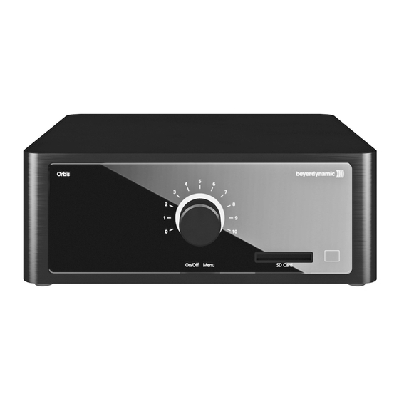
Page 7: Orbis Cu Control Unit
Orbis CU Control Unit The Orbis CU control unit is the heart of the system. With one Orbis CU control unit a maximum of 8 speakers (e.g. 7 delegates and 1 chairman) can speak simultaneously. Each chairman unit in the system is allocated to a channel. - Page 8 µ Connection for microphone units line 1, RJ45 (Warning: No Ethernet Connection) ¸ Connection for microphone units line 2, RJ45 (Warning: No Ethernet Connection) ¹ 48 V DC connection for power supply unit Important: Only use the power supply unit supplied by beyerdynamic. Bottom Reset to restore the factory settings...
-
Page 9: Orbis Mu Microphone Unit
• Orbis MU 41: built-in delegate microphone unit with button for microphone • Orbis SU 63: system unit installation under the table. Depending on the number of the connected buttons, the system unit acts as chairman (buttons for microphone, clear, function) - Page 10 Orbis – Microphone Unit Orbis MU 23 Top View Orbis MU 21 Top View Opening for unlocking the gooseneck Microphone button microphone “Clear” button to clear all delegate Connection for gooseneck microphone, microphones 5-pin XLR Programmable function button Orbis MU 43/41 Bottom...
- Page 11 Orbis – Microphone Unit Orbis MU 43 Top View Orbis MU 41 Top View Headphone connection, 3.5 mm stereo Connection for gooseneck microphone, jack 5-pin XLR Channel selector button “Clear” button to clear all delegate microphone units Volume button to reduce the headphone...
- Page 12 The Orbis SU 63 is connected to the Orbis CU control unit via the RJ45 sockets. Furthermore, the RJ45 sockets are used to connect the Orbis SU 63 system unit among each other or to other Orbis MU microphone units.
- Page 13 Speak LED: connector for an external LED, which displays the ready-to-speak status of the microphone LED-Power: voltage source for the external LED 5-pin Phoenix connector Via the 5-pin Phoenix connector you can connect a headphone and loudspeaker to the Orbis SU 63 system unit. Headphone R and Headphone L: headphone connector Ground: ground...
-
Page 14: Installation
Installation 3.2.1 Orbis MU 23/21 Microphone Unit The Orbis MU 23 and Orbis MU 21 microphone units have two threads on the bottom to attach the microphone unit on a table top. Use the appropriate drilling template to drill the holes into the table top. -
Page 15: Orbis Mu 43/41 Built-In Microphone Unit
3.2.2 Orbis MU 43/41 Built-in Microphone Unit For the base of the Orbis MU 43/41 built-in microphone unit you must provide a cutout in the table top which is large enough to mount the base with the supplied mounting brackets to the table. - Page 16 Orbis – Installation Orbis MU 4x Base Installation Orbis MU 4x and optional CA OL loudspeaker in table top...
-
Page 17: Orbis Su 63 System Unit
Orbis – Installation 3.2.3 Orbis SU 63 System Unit The Orbis SU 63 system unit provides mounting brackets for a variable installation, e.g. directly under the table or upright into an armrest. • Provide appropriate holes for the button, microphone and loudspeaker in the table top or armrest. - Page 18 Orbis – Installation Direct installation During installation, make sure that you use screws that are suitable for your application (not included in the delivery). Mounting bracket Mounting bracket Mounting bracket Direct installation under a table Mounting bracket...
-
Page 19: Operation
5 seconds. The corona will illuminate red. • In order to disconnect the Orbis CU control unit from the mains, pull the power supply from the AC mains outlet. Audio connection to the control unit • The control unit is provided with a balanced and analogue unbalanced audio output (Audio Out). - Page 20 CAT5e cables (S/UTP, min. AWG 26 diameter or better). The audio transmission, power supply and control is made via one cable. The system capacity is achieved by the economical Orbis MU microphone unit, which is less than 1 watt when operated and at maximum volume.
- Page 21 The cable concerned or the defective microphone unit/system unit can be replaced during operation without failing all other microphone units/system units. Orbis CU control unit max. 50 microphone units in a ring...
-
Page 22: Menu Settings Control Unit
Examples: 1. Four chairman microphone units in the system. On the Orbis CU control unit the NOM has been set to “4”. The fifth chairman microphone unit is connected. The NOM display on the Orbis CU control unit changes to “3”, because determined by the network there is only a max. NOM of 3 possible. - Page 23 Orbis – Operation Volume The “Volume” menu is used to adjust the volume of the loudspeakers of the microphone units. The volume can be displayed from 0 to 10 or by turning the rotary encoder The volume is always displayed by default when other settings are completed on the menu or when the rotary encoder has not been operated for more than 5 seconds.
- Page 24 • The red LED ring of the gooseneck microphone illuminates and the microphone button illuminates green: The microphone is ready to talk. • Depending on the setting of the Orbis CU control unit up to 8 participants (e.g. 7 delegates and 1 chairman) can speak simultaneously.
- Page 25 AUX in: • Here the audio signal of the “Aux in” input on the Orbis CU control unit will be reproduced. Mic + AUX in • Both settings can be selected simultaneously so that over the loudspeakers of the microphone units both audio signals can be heard.
-
Page 26: Status Displays Of The Control Unit
Ext. Control If an external device, e.g. a media control system is connected to the RS 232 interface of the Orbis CU control unit, the conference system is in the so-called “Ext. Control” mode and can be controlled via an external media control system. - Page 27 The settings on the control unit can be protected via a key combination or an external device. The “Lock” function can be activated/deactivated, if there is no SD card in the slot of the Orbis CU control unit. The “Lock” function is in two stages. When pressing the “REC” button the first time, the system settings will be locked, the system volume however can still be selected.
-
Page 28: Recording Of The Conference
Recording of the Conference With the Orbis conference system you can record a conference. Via an external device connected to the RS 232 interface you can set the integrated clock so that you can enter the date and time on the SD card. -
Page 29: How To Connect A Gooseneck Microphone To The Microphone Unit
Orbis – Operation How to Connect a Gooseneck Microphone to the Microphone Unit Warning! – When mounting or removing the gooseneck microphone hold it at the bottom end only. Never hold it at the gooseneck or microphone head! You could damage the gooseneck microphone and by doing so you will invalidate the guarantee. -
Page 30: Buttons And Functions Of The Chairman Microphone Unit
Refer also to the issue “Priority” in chapter “4.2 Menu Settings of the Control Unit”. Operating Modes The different operating modes such as “Normal”, “FiFo” or “Voice activated” are set on the Orbis CU control unit for all microphone units. The factory set operating mode is “Normal”. Refer also to the issue “Mode”... -
Page 31: Configuration Of The Microphone Units/System Units
LED ring of the gooseneck flashing red. 8. End the configuration mode on the Orbis CU control unit by pressing the rotary encoder once (pressing or turning). -
Page 32: How To Localise The Microphone Units/System Units
7. Press the microphone button of the delegate microphone unit, which you would like to configure as press unit, until the microphone button illuminates orange. 8. End the configuration mode on the Orbis CU control unit by operating the rotary encoder once (pressing or turning). -
Page 33: Reset Factory Settings
• Make sure not to allow any water to enter the microphone capsule or housing. • Clean the pop shield of the gooseneck microphone for Orbis MU with clear, warm water. Make sure that it is completely dry before you put it on the microphone again. -
Page 34: Application Examples
Orbis – Operation Application Examples Tele Conference Cables Orbis CU AUX Input – External Device Output Orbis CU AUX Output – External Device Input Settings on the Orbis CU control unit: Audio Out: Mic Speaker: Aux In Video Conference Last Mic Hold via external device for echo cancellation (if voice-activated mode is active) “N-1”... -
Page 35: Components
Control unit CA OR Rack mount set for Orbis CU..... . . Order # 725.897 Control unit, microphone units/system units CA OC 1 System cable, Cat5 with RJ45 connector, 1 m . -
Page 36: Technical Specifications
Orbis – Technical Specifications Built-in microphone unit/system unit CA OL Loudspeaker module for Orbis MU 41/43 and Orbis SU 63 . . Order # 725.765 System unit CA OP 2 Piezo button for Orbis SU 63, aluminium black anodised, with LED spot illumination, without inscription..Order # 725.773 CA OP 2 C same as above, but with “Clear”... - Page 37 Specification line connector ... . RJ45 acc. to EIA/TIA 568-B, shielded Min. cable diameter ....AWG 26 Orbis MU 23/21 Microphone Unit General Voltage supply via control unit .
- Page 38 Orbis – Technical Specifications Orbis SU 63 System Unit General Voltage supply via control unit ..Bus voltage (48 V DC) Power consumption ....max. 1.1 W Temperature range (humidity <...
- Page 39 Orbis – Technical Specifications Orbis SU 63 Pin Assignment Example: XLR socket for GM xxx Q...
- Page 40 Theresienstrasse 8, 74072 Heilbronn, Germany Type of Equipment: Conference Control Unit Model Numbers: Orbis CU I, the undersigned, as an employee of beyerdynamic, hereby declare that the equipment specified conforms to the above Directive and Standards. Manufacturer's Signature: Full Name: Ulrich Roth Date: 1.
-
Page 41: Declaration Of Conformity
Orbis – Declaration of Conformity DECLARATION OF CONFORMITY This device complies with Part 15 of the FCC Rules. Operation is subject to the following two conditions: (1) This device may not cause harmful interference, and (2) This device must accept any interference received, including interference that may cause undesired operation. - Page 42 Type of Equipment: Conference Microphone Unit Model Numbers: Orbis MU 21, Orbis MU 23 I, the undersigned, as an employee of beyerdynamic, hereby declare that the equipment specified conforms to the above Directive and Standards. Manufacturer's Signature: Full Name: Ulrich Roth Date: 1.
- Page 43 Phone: Tel. (631) 293 3200 Fax: (631) 293 3288 Conference Microphone Unit Model/Type: Orbis MU 21, Orbis MU 23 Classification: Class B Digital Device We hereby declare that the equipment bearing the trade name and model number specified above was tested conforming to the applicable FCC rules under the most accurate...
- Page 44 Theresienstrasse 8, 74072 Heilbronn, Germany Type of Equipment: Conference Microphone Unit Model Numbers: Orbis SU 63 I, the undersigned, as an employee of beyerdynamic, hereby declare that the equipment specified conforms to the above Directive and Standards. Manufacturer's Signature: Full Name: Ulrich Roth Date: 1.
- Page 45 (1) This device may not cause harmful interference, and (2) This device must accept any interference received, including interference that may cause undesired operation. Manufacturer: beyerdynamic GmbH & Co. KG Theresienstrasse 8 D- 74072 Heilbronn, Germany U.S. Responsible Party: beyerdynamic, Inc.
- Page 46 GmbH & Co. KG Theresienstr. 8 | 74072 Heilbronn – Germany Tel. +49 (0) 7131 617 - 0 | Fax +49 (0) 7131 617 - 204 info@beyerdynamic.de | www.beyerdynamic.com For further distributors worldwide, please go to www.beyerdynamic.com...
Need help?
Do you have a question about the Orbis and is the answer not in the manual?
Questions and answers