Table of Contents
Advertisement
Quick Links
OWNERS MANUAL
INSTALLATION AND OPERATION INSTRUCTIONS
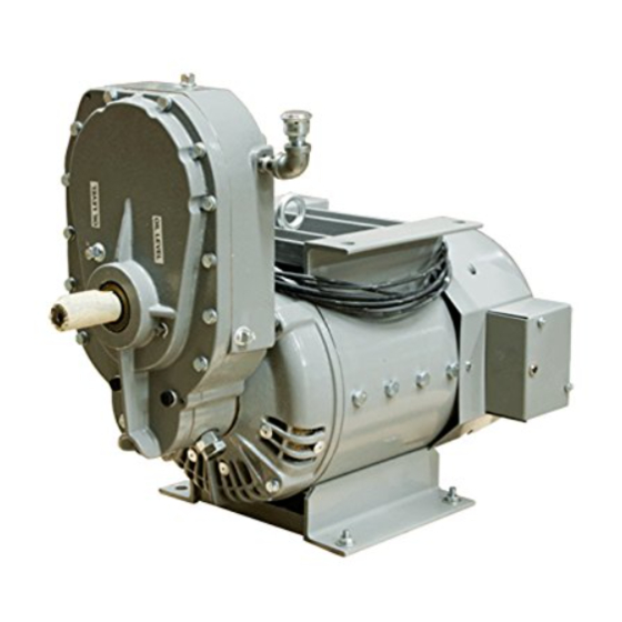
SIDE VIEW
DRIVE END VIEW
SAFETY FIRST
READ THIS MANUAL BEFORE OPERATING YOUR GENERATOR.
Chassis Mount
PTO Generators
TOP VIEW
Note: Unit shown is the ECV2512 the only
dimension that changes on the ECV2510 is
the location of the input shaft
ECV2510-3
ECV2512-3
60706-130
Advertisement
Table of Contents

Related Manuals for Winco ECV2510-3


Summary of Contents for Winco ECV2510-3
-
Page 1: Safety First
Chassis Mount PTO Generators OWNERS MANUAL ECV2510-3 INSTALLATION AND OPERATION INSTRUCTIONS ECV2512-3 SIDE VIEW TOP VIEW Note: Unit shown is the ECV2512 the only dimension that changes on the ECV2510 is the location of the input shaft DRIVE END VIEW SAFETY FIRST READ THIS MANUAL BEFORE OPERATING YOUR GENERATOR. -
Page 2: Table Of Contents
COPY YOUR MODEL AND SERIAL NUMBER HERE listed in this manual describes what you can expect from No other WINCO generator has the same serial number as WINCO should you need service assistance in the future. yours. It is important that you record the number and other... -
Page 3: Guide To Product Safety
DEADLY EXHAUST GAS - Exhaust fumes from any engine SAFETY INFORMATION contain carbon monoxide, an invisible, odorless and deadly gas that must be mixed with fresh air. This generator set has been designed and manufactured to allow safe, reliable performance. Poor maintenance, Operate only in well ventilated areas. -
Page 4: Description
Be certain they can handle the WINCO thoroughly tests each of these generators before intended load and are compatible with the required vehicle shipment. All are continuous duty rated. -
Page 5: Mounting
2. Location. Locate as close to electrical service as pos- sible. This will reduce the cost of electrical and minimize the losses in the power conductors. Position the unit to keep clear of the drive line and exhaust runs. 3. Mounting Support. Frame loading, frame type and strength should be taken into consideration when installing an emergency rescue generator under a truck. -
Page 6: Pre-Wire Checklist
The PTO drive shaft should be maintained in as straight a line *****Notice ***** as possible. Install the generator so the drive line is aligned to within 5 degrees (10 degrees Max). The 2510/2512 PTO units If for any reason during the check-out procedure the will require about 50 Hp to maintain full output, be sure that voltage and frequency are not correct, stop the engine and the auxiliary drive on the vehicle transmission and the gear... -
Page 7: Final System Check
H. FINAL SYSTEM CHECK is recommended that the generator be operated at least monthly under normal loads to familiarize operators with the procedures and controls as well as to dry out any accumu- Recheck voltages at mainline circuit breaker. Voltages lated condensation or other moisture in the generator electri- should match readings taken at the pre-wire check- cal windings. - Page 8 Remove all brushes. Ground fault test - set multimeter to read high resistance (meg-ohms).Holding one meter lead against a clean spot on the armature shaft, touch the other lead to each of the slip rings (one at a time) while observing the meter. If meter indicates continuity (any reading lower than one meg- ohm), the armature is grounded.
-
Page 9: Lubrication
Reverse the meter leads, (black lead to the DC POS (+) The drive shaft (tumbling bar) requires greasing. Keep the and red to the AC terminals, each in turn. An opposite universal joints in the coupling shaft free from grease and dirt reading should be observed. -
Page 10: Trouble Shooting Table
TROUBLE SHOOTING TABLE SYMPTOM CAUSE(S) CORRECTIVE ACTION No output 1. Circuit breaker open. 1. Reset circuit breakers, replace if defective. voltage. 2. Defective voltmeter. 2. Check output with another meter, replace meter if defective. 3. Short circuit in the load. 3. -
Page 11: Automatic Voltage Regulator
AUTOMATIC VOLTAGE REGULATOR ASSEMBLY DESCRIPTION PART NBR Voltage Regulator 98884-002 Mounting Bracket 64790-000 Grommet 9336-000 Machine Screw 16165-000 Lockwasher 484-000 Flat Washer 598-000 Hex Nut 6372-000 Sleeving 64620-002 Circuit Breaker 91286-003 Cover 64791-001 7150-01 60706-130 Page 9... -
Page 12: Generator Parts List
GENERATOR ILLUSTRATION 7150-01 Page 10 60706-130... -
Page 13: Technical Data
GENERATOR REPLACEMENT PARTS LIST DESCRIPTION PART NBR. DESCRIPTION PART NBR. Cap Screw 5/16”-18x2 3/4 51101-000 Hex Nut 20160-000 Lockwasher 5/16” 480-000 Armature Assembly 64794-000 Lockwasher Split Type ¼” 479-000 Armature 64794-001 Machine Screw 45633-000 Bearing 50215-000 Lockwasher 11/16 Int. 40552-000 Field Shell &... -
Page 14: Gear Box Part List
1000 RPM 1181 RPM DESCRIPTION PART NBR. PART NBR Gear Box Assembly 54661-001 64557-000 Pinion Gear 44833-000 Seal 20029-000 20029-000 Bearing 64562-000 64562-000 Shaft (Input Drive) 46296-000 64556-000 Woodruff Key 1774-000 1774-000 Gear (input Drive) 44832-000 46546-000 Gasket (Cover) 20016-000 20016-000 Backing Plate Safety Shield... -
Page 15: Wiring Diagram
7150-01 60706-130 Page 13... -
Page 16: Month Warranty
LIMITED WARRANTY WINCO, Inc., warrants for 12 months or 500 hours which ever occurs first from date of shipment, that it will repair or replace at its option, for the original user, the whole or any part of the product found...
Need help?
Do you have a question about the ECV2510-3 and is the answer not in the manual?
Questions and answers