Table of Contents
Advertisement
Quick Links
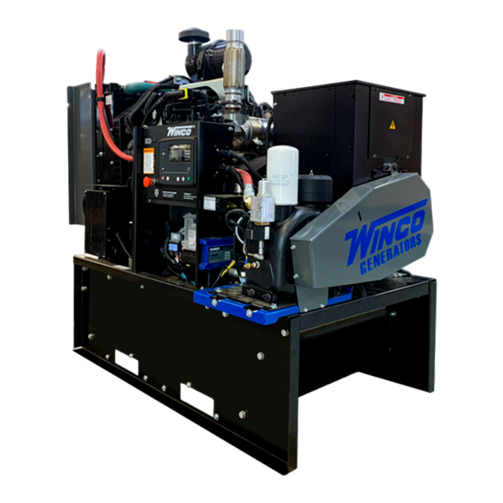
DE4040F4-XX/3
GENERATOR
INSTALLATION AND
OPERATORS MANUAL
COPY YOUR MODEL AND SERIAL NUMBER HERE
No other WINCO generator has the same serial number as yours.
If you should ever need to contact us on this unit, it will help us to
respond to your needs faster.
MODEL __________________________________________________
SERIAL NUMBER _________________________________________
PURCHASE DATE _________________________________________
DEALER NAME ___________________________________________
DEALER PHONE # ________________________________________
www.wincogen.com
Advertisement
Table of Contents

Related Manuals for Winco DE4040F4


Summary of Contents for Winco DE4040F4
- Page 1 OPERATORS MANUAL COPY YOUR MODEL AND SERIAL NUMBER HERE No other WINCO generator has the same serial number as yours. If you should ever need to contact us on this unit, it will help us to respond to your needs faster.
-
Page 2: Table Of Contents
“Troubleshooting Tables” near the end of this manual. CHANGING THE OIL FILTER The warranty listed in the manual describes what you can REPLACING FINE SEPARATOR CARTRIDGE expect from WINCO should you need service assistance in REPLACING THE AIR INTAKE FILTER the future. OPM-141/E... -
Page 3: Safety Information
SAFETY INFORMATION SAVE THESE INSTRUCTIONS B. Keep fuel containers out of reach of children. C. Do not smoke or use open flame near the generator This engine generator set has been designed and set or fuel tank. manufactured to allow safe, reliable performance. Poor D. -
Page 4: Specifications
SPECIFICATIONS DE4040F4 MODEL DE4040F4-3 DE4040F4-4 DE4040F4-17 DE4040F4-18 DE4040F4-21 GENERATOR Watts 40,000 40,000 40,000 40,000 40,000 Volts 120/240 120/208 120/240 277/480 346/600 Phase Single Three Three Three Three Amps Hertz GENERATOR RESISTANCE (all value at 22°C) Model Stamford UCI224D Winding Group Rotor 0.64 Ω... -
Page 5: Testing Policy
Rated output of generator is based on engineering tests Go to the WINCO website for a list of engine dealers of typical units, and is subject to, and limited by, the (wincogen.com) or contact the WINCO Service Department. -
Page 6: Preparing The Unit
This must be completed and If the generator was shipped on the fuel tank, use the returned to WINCO Inc. within 180 days of the factory lifting points located on the fuel tank to move the entire invoice date. -
Page 7: Installation
The flange should not be placed closer than 0.75 in. to the edge of the structure or other The WINCO installation manual OPM-112 contains solid surfaces. The radiator is mounted on rubber vibration additional information on indoor installations and isolators that allow it to move. -
Page 8: Exhaust Installation
EXHAUST INSTALLATION INSTALLING THE FUEL LINE WARNING: PERSONAL INJURY Engine-generator sets are properly adjusted before they leave the factory. Connecting a fuel supply with adequate Improper exhaust installation will allow dangerous gases supply volume is critical to reliable operation. Diesel units to seep into enclosed spaces causing a hazard to your with optional base mounted fuel tanks are pre-plumbed to health and/or death. -
Page 9: Grounding
The NFPA 70 250:34-35 are good technical references. VEHICLE-MOUNTED GENERATOR Your WINCO generator ships with a bonded neutral. When mounted to a vehicle to safely distribute power it is necessary that the generator frame is bonded to the vehicle frame. -
Page 10: Dc Wiring
AC wiring. to be adjusted using the free DSE configuration software to REMOTE START enable the commutation. Contact Winco service for a list of register values. The DSE7310 is able to start the generator when it receives a remote signal from any dry contact. -
Page 11: Servicing Batteries
All connections must be clean and tight. Check the CAUTION electrolyte in the battery periodically to be sure it is A battery presents a risk of electrical shock and high above the plates. Never allow the battery to remain in a short circuit current. -
Page 12: Starting Procedure
(1) using a clean cloth and then put it back into weather. We have partnered with a national lubrication oil its seat (2). Remove the dipstick (1) again and check the manufacturer to give you access to Winco private branded level. premium oil available at comparable prices to conventional oils. -
Page 13: Control Layout
CONTROL LAYOUT SHUTDOWN Shutdowns are critical alarm conditions that stop the engine and draw the operator’s attention to an undesirable condition. Shutdown alarms are latching. The fault must be removed and the STOP/RESET button pressed to reset the module. The icon will be flashing in the display. -
Page 14: Auto Mode
to insure proper rotation will cause three phase motors to spin backwards possibly damaging them. NOTICE: If for any reason during the check out procedure the voltage and frequency are not correct, depress the STOP/ RESET button and correct the trouble before proceeding. 4. -
Page 15: Operating Conditions
OPERATING CONDITIONS Inspect the CV filters and hoses regularly during cold NORMAL OPERATION operation looking for signs of freezing. If the line freezes it will cause pressure to build in the crankcase and may cause This generator set is designed to be operated under load an engine seal failure. -
Page 16: Air Compressor
AIR COMPRESSOR do this may result premature wear and failure of the drive This unit has been equipped with an air compressor that belts, damage to the equipment, or poor performance. uses an auxiliary shaft from the generator to provide 120 There are several things to keep in mind when adjusting PSI @ 40 CFM the compressor. -
Page 17: Checking The Oil Level
Operating Materials”. Add oil of the same oil disconnect the battery type from the same manufacturer. to prevent the engine WINCO recommends our Rotorcomp maintenance kit, Switching over to another oil type can require the from starting. compressor module to be flushed. -
Page 18: Replacing Fine Separator Cartridge
6. Check the filter for leaks while the system is running. 1. Switch off the compressor and disconnect the battery to prevent the engine from starting. 7. Turn off compressor and check oil level. Top off to the maximum level if needed. 2. -
Page 19: Engine Maintenance
(2). oil below the drain valve attached to the sump (5). WINCO has supplied a valve to hook a customer 4. Moisten the gasket (2) with a thin layer of oil and place it in its seat on the oil filter (1). -
Page 20: Changing Air Filter
CLEANING RADIATOR the radiator is above the minimum level. 3. Refill if necessary. The surfaces of the radiator come into contact with the outside air and can be subject to deposits and impurities. CHANGING AIR FILTER Clean in accordance to the maintenance schedule with compressed air or steam. -
Page 21: Storage
STORAGE Using Illustration 2: 1. Loosen the nut (2) PREPARING THE ENGINE FOR A LONG PERIOD OF INACTIVITY 2. Disconnect the fittings (1)(4). In the case of a planned period of inactivity that lasts longer 3. Remove the vapor recirculation pipe (3). than two months, to prevent the interior parts of the engine and some components of the injection system from oxidizing, prepare the engine as follows:... -
Page 22: Trouble Shooting
MAINTENANCE SCHEDULE TROUBLE SHOOTING ENGINE ENGINE-GENERATOR SET Checks In Period of Use Frequency Problem Possible Causes Check for water in the fuel Pre-Filter Daily Unit will not crank when Digital genset not in AUTO Check Air-Restriction Indicator on Filter Daily power fails Transfer control switch not in AUTOMATIC position... -
Page 23: Compressor
1.7 Nameplate only be used to compress gases or other media For the location of the nameplate, see Figure 3-1 following written approval by ROTORCOMP. or 3-3. The NK 31 may only be installed by specialized companies with the corresponding know-how. The safety precautions, technical data, limits, in- Should you have questions, please provide us COMPRESSOR... -
Page 24: Engine Codes
ENGINE CODES FMI Test Translation The electrical Signal of the EGR Valve position sensor is monitored. In case of defect recognition a replacement value is 1B-3 taken. The electrical Signal of the EGR Valve position sensor is monitored. In case of defect recognition a replacement value is 1B-4 taken. - Page 25 FMI Test Translation The Fuel Rail pressure control is executed with a device: Metering Unit (MeUn) as feeding quantity control and an 9D-12 overpressure valve allocate in the rail (PRV). Dataset Interlock Feature is used to prevent the flashing of unintended datasets on to the ECU during any SW upgrades A6-2 in field.
- Page 26 FMI Test Translation Hardware errors in the injectors and respective ECM power stages are investigated. Diagnostic procedure uses pattern detection to identify specific errors and trigger appropriate substitute reaction. The behavior pattern describes in a 28C-5 bit mask different detected problem (overcurrent, command collision, RAM error,short circuit,..) when the expected combination of errors is detected (measured and reference pattern are matching) a failure is detected.
- Page 27 FMI Test Translation Engine Starter is controlled by two relays actuators one for Low Side and one for High Side. Both power stages are 2A4-6 monitored by Hardware for electric failures. The Engine Position Management module is responsible for signals from camshaft and crankshaft sensor evaluation: angle and speed determination, signal plausibility and quality are monitored by this module.
- Page 28 FMI Test Translation The Power stage of EGR Valve actuator is monitored by Hardware for electric failures. The Power stage of electric EGR Valve actuator (H-Bridge) is monitored by Hardware for electric failures. The H-Bridge has 2 switches (High side and Low side). Each circuit is monitored separately. The Power stage of electric EGR Valve actuator (H-Bridge) is monitored by Hardware for electric failures.
- Page 29 FMI Test Translation 4009 The Power stage of Fuel Filter heater is monitored by Hardware for electric failures. FA9-5 4009 The Power stage of Fuel Filter heater is monitored by Hardware for electric failures. FA9-6 The electrical Signal of the Oxi Cat temperature upstream sensor is monitored. In case of defect recognition a substitute 4765 129D-3 value is taken.
-
Page 30: Wiring Size Table
WIRING SIZE TABLE The table below is based on Table 310.15 (B) (16) un the National Electric Code 2014 edition. Allowable ampacitier of insulated conductors rated 0 through 2000V, 75°C through 90°C. Not more than three current-carrying conductors in Raceway, Cable, or Earth (direct buried). Adjust for 40°C (104°F) ambient temperature. -
Page 31: Engine Harness
ENGINE HARNESS OPM-141/E... -
Page 32: Dse7310 Wiring Diagram
DSE7310 WIRING DIAGRAM OPM-141/E... -
Page 33: Wiring Diagrams
WIRING DIAGRAMS THREE PHASE AC WIRE HIGH AND LOW WYE THREE PHASE AC WIRING- DELTA SINGLE PHASE 311 WINDING OPM-141/E... -
Page 34: Ca Emission Control Warranty
CALIFORNIA EMISSION CONTROL WARRANTY STATEMENT YOUR WARRANTY RIGHTS AND OBLIGATIONS California Air Recourses Board and FPT Industrial S.p.A. are pleased to explain the emission control system warranty on 2018 to 2020 off-road engines. In California, new heavy-duty off-road engines must be designed, built, and equipped to meet the state’s stringent anti-smog standards. -
Page 35: Environmental Warranty
(12) months afterwards for a maximum of twenty-four (24) months for warranty coverage to be available, and provide written confirmation to WINCO inc that the engine was revalidated. Warranty will be exhausted if the unit is still in the seller’s inventory after revalidation cycle. -
Page 36: Limited Warranty
Warranty service may be performed by an authorized WINCO Inc. service center only. Service work performed by unauthorized persons will void all warranties. WINCO Inc. shall not be liable for any claim in an amount greater than the purchase price of the product. In no event shall WINCO Inc. be held liable for any special, indirect, consequential or liquidated damages.
Need help?
Do you have a question about the DE4040F4 and is the answer not in the manual?
Questions and answers