Table of Contents
Advertisement
Quick Links
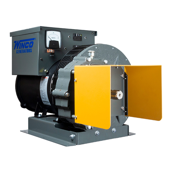
27.6kW-36kW
PTO GENERATORS
INSTALLATION AND
OPERATORS MANUAL
COPY YOUR MODEL AND SERIAL NUMBER HERE
No other WINCO generator has the same serial number as yours.
If you should ever need to contact us on this unit, it will help us to
respond to your needs faster.
MODEL __________________________________________________
SERIAL NUMBER _________________________________________
PURCHASE DATE _________________________________________
DEALER NAME ___________________________________________
DEALER PHONE # ________________________________________
www.wincogen.com
Advertisement
Table of Contents

Related Manuals for Winco 27PTOC4-03


Summary of Contents for Winco 27PTOC4-03
- Page 1 OPERATORS MANUAL COPY YOUR MODEL AND SERIAL NUMBER HERE No other WINCO generator has the same serial number as yours. If you should ever need to contact us on this unit, it will help us to respond to your needs faster.
-
Page 2: Table Of Contents
Should you experience a problem please follow the “Troubleshooting Tables” near the end of this manual. INTRODUCTION The warranty listed in the manual describes what you can TESTING POLICY expect from WINCO should you need service assistance in PREPARING THE UNIT the future. UNPACKING INSTALLATION... -
Page 3: Safety
SAFETY IMPORTANT SAFETY INSTRUCTIONS CAUTION This engine generator set has been designed and Keep the generator and surrounding area clean. manufactured to allow safe, reliable performance. Poor A. Remove all grease, ice, snow or materials that maintenance, improper or careless use can result in create slippery conditions around the unit. -
Page 4: Specifications
SPECIFICATIONS GEAR LUBE 30PTOT4-17 Volume 0.875 Pint Watts 31,600 Type SAE 80-90W-140 Volts 120/240 Phase Three 27PTOC4-03 Amps Input Speed 1000 RPM Watts 27,600 Generator Speed 1800 RPM Volts 120/240 AS540 Phase Single Input Shaft 1 3/8” 6-spline Amps Required Tractor PTO HP... -
Page 5: Introduction
The WINCO power take-off generators are designed primarily for farm use as a standby electrical power supply, utilizing the power take-off of a tractor or truck as the prime mover. -
Page 6: Preparing The Unit
1. As you receive your unit, it is critical to check it for any damage. If any damage is noted, it is always easiest to refuse the shipment and let WINCO take care of the freight claim. If you sign for the unit, the transfer of the ownership requires that you file the freight claim 2. -
Page 7: Installation
INSTALLATION FOUNDATION MOUNTING C. The trailer height and mounting position of the generator on the trailer should enable aligning the drive shaft (tumbling bar) in a straight or nearly straight line between the power take-off and generator input shafts. Misalignment must be less than 5 degrees during generator operation, even though the mechanical design of the tumbling bar would allow greater misalignment. -
Page 8: Electrical Connections
Your application and local code will determine the type of wire used. WINCO’s recommended wire size is given in This WINCO portable generator ships with a bonded each plug kit. - Page 9 WARNING: EQUIPMENT DAMAGE Never use acid core solder. When soldering insure no excess solder runs down on the contact surface - Solder on the contact surface will not allow the contacts to mate properly causing them to burn up. Each wire should be stripped back 7/8 of an inch and inserted into one of the contacts in the plug kit.
- Page 10 TYPICAL CONNECTION METHODS FOR GENERATOR POWER SERVICE IMPORTANT: When making standby service hook up, make sure load to be transferred to standby generator will not exceed generator rating. TYPICAL HOOK UP FOR TYPICAL HOOK UP FOR SUPPLYING ALL CIRCUITS SUPPLYING ONLY ESSENTIAL CIRCUITS WITH EMERGENCY POWER WITH EMERGENCY POWER To Power Line Master Switch...
-
Page 11: Operation
OPERATION OUTPUT POWER AVAILABLE AND LOAD DETERMINATION Before using the generator, read and understand the following information. Generator output current (amperage) is internally limited by three circuit breakers. If too much demand is placed on a generator output (if you try to drive too many motors with it, for example), one of the circuit breakers will trip, cutting off the output in order to protect the generator. -
Page 12: Pre-Start Checks
PRE-START CHECKS 4. Couple the tractor to the generator with the drive shaft (tumbling bar). Couple the tumbling bar to the generator WARNING: PERSONAL INJURY input shaft first, then to the power take-off shaft. Check When working on or around these generators, do not alignment, tractor, power take-off shaft (tumbling bar), wear loose fitting clothing or any articles that may get and the generator input shaft should form a straight (or... -
Page 13: Generator Procedures
GENERATOR PROCEDURES START-UP 1. With the power take-off drive disengaged, start the engine which will drive the generator. Run the engine long enough to warm it up before proceeding, so that it will run smoothly and achieve full power under generator load. -
Page 14: Maintenance
MAINTENANCE NOTE: TENANCE Do not over lubricate the universal joints. NOTE: GENERAL INFORMATION Do not over lubricate the universal joints. al Information The main components of the generator are: rotor and stator assembly, cooling fan, brushes, brush holder assembly, n components of the generator are: armature, field end brackets. -
Page 15: Cleaning & Inspection
metal. Fine metal dust in the oil does not indicate trouble, but metal chips do. Dismantle the gearcase and look for damaged gears if you find metal chips in the oil. 4. Replace the oil drain plug. Refill the gearcase through the breather port with new oil of the recommended type. -
Page 16: Trouble Shooting Table
TROUBLE SHOOTING TABLE SYMPTOM POSSIBLE CAUSE CORRECTIVE ACTION Low Output Voltage 1. Engine speed too slow. 1. Check engine speed. Increase RPM if necessary. 2. Generator overloaded. 2. Reduce load if it is higher than the rated capacity of the generator. See generator nameplate. 3. -
Page 17: Wiring Diagram
WIRING DIAGRAM 120/240V SINGLE PHASE BACK VIEW OPM-136/D... -
Page 18: 120/208V & 120/240V Three Phase
120/208V & 120/240V THREE PHASE BACK VIEW OPM-136/D... -
Page 19: 277/480V Three Phase
277/480V THREE PHASE BACK VIEW OPM-136/D... -
Page 20: 36 Month Limited Warranty
LIMITED WARRANTY 36 MONTH LIMITED WARRANTY WINCO, Inc., warrants for thirty-six months from date of shipment, that it will repair or replace at its option, for the original user, the whole or any part of the product found upon examination,...
Need help?
Do you have a question about the 27PTOC4-03 and is the answer not in the manual?
Questions and answers