Roland M-5000 Quick Start Manual
Live mixing console
Hide thumbs
Also See for M-5000:
- Reference manual (276 pages) ,
- Reference manual (230 pages) ,
- User manual (27 pages)
Table of Contents
Advertisement
Quick Links
Quick Start
This document describes the basic matters and procedures needed for working with the M-5000.
In addition to the explanations in this guide, a separate PDF document containing descriptions of screen operations and other detailed usage
procedures is also available.
For more information, refer to p. 11.
Copyright © 2014 ROLAND CORPORATION
All rights reserved. No part of this publication may be reproduced in any form without the written permission of ROLAND CORPORATION.
Before using the M-5000, ensure that its system program is at the most recent version. For information on available upgrades for the system program,
see the Roland website.
Advertisement
Table of Contents

Subscribe to Our Youtube Channel
Related Manuals for Roland M-5000


Summary of Contents for Roland M-5000
-
Page 1: Quick Start
All rights reserved. No part of this publication may be reproduced in any form without the written permission of ROLAND CORPORATION. Before using the M-5000, ensure that its system program is at the most recent version. For information on available upgrades for the system program,... -
Page 2: Important Safety Instructions
WARNING: To reduce the risk of fire or electric shock, do not expose this apparatus to rain or moisture. The lightning flash with arrowhead symbol, within an CAUTION equilateral triangle, is intended to alert the user to the RISK OF ELECTRIC SHOCK presence of uninsulated Òdangerous voltageÓ... -
Page 3: Instructions Importantes De Sécurité
AVERTISSEMENT: Pour éviter les risques d’incendie ou de choc électrique, ne pas exposer cet appareil à la pluie ou à l’humidité. L’éclair éché dans un triangle équilatéral est destiné à ATTENTION avertir l’utilisateur de la présence, dans l’appareil, d’une RISQUE DE CHOC ÉLECTRIQUE zone non-isolée soumise à... -
Page 4: Using The Unit Safely
• Subject to high levels of vibration and shakiness. from the power outlet. To make this possible, plug the may cause short circuits, faulty operation, power cord into a power outlet that is as close to the M-5000 Do not place in an unstable location or other malfunctions. - Page 5 Before using the unit in overseas, consult grasp the power cord by its plug when disposal that may be observed in the with your retailer, the nearest Roland disconnecting it from this unit or from a region in which you live.
-
Page 6: Consignes De Sécurité
EXT. POWER DC INPUT, étrangers (ex : objets inflammables, puis retirez la fiche du M-5000 de la prise. Pour ce pièces, fils) ou des liquides (ex : eau, Ne pas placer à un endroit instable faire, branchez le cordon d’alimentation à... - Page 7 (p. 23). Assurez-vous de les insérer en Roland ou un distributeur Roland agréé, l’appareil ou d’une prise de courant. respectant les instructions (pour que la comme indiqué dans les “informations”.
-
Page 8: Important Notes
Inc. • Do not paste stickers, decals, or the like to this internal elements. • Roland, REAC are either registered trademarks or instrument. Peeling such matter off the instrument • A small amount of heat will radiate from the unit trademarks of Roland Corporation in the United may damage the exterior finish. - Page 9 IMPORTANT NOTES...
-
Page 10: Table Of Contents
Utilisation de l’attache du cordon d'alimentation Using the Power-cord Hook Connecting Backup Power to the M-5000 Utilisation du Crochet du cordon d’alimentation Raccordement d’une alimentation de secours au M-5000 Disconnecting Backup Power Turning the Power On and Off Turning the Power On Turning the Power Off Déconnexion de l’alimentation de secours... - Page 11 This adds to the procedures in Quick Start by describing the operation procedures at the various screens and other detailed usage methods. RCS User’s Guide (PDF) This describes how to use the M-5000 RCS dedicated remote-control software that runs under Windows or on a Macintosh computer. Remote User’s Guide (PDF) This describes how to use the M-5000 Remote dedicated remote-control software that runs on an iPad.
-
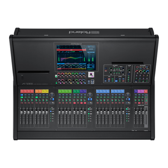
Page 12: Main Features
So what do you think? It's clear that the M-5000 has an extremely powerful mixing engine. High Resolution All elements installed in the M-5000 operate at a sample rate of 96 kHz. Not only AD/DA but the mixing engine as well operate at 96 kHz. All effect algorithms operate at 96kHz. -
Page 13: Display Section
The fader bank section, where 24 faders are provided, can also be used as independent sets of 8 faders or as interlinked sets of 16 or 24 faders. The decision on how to use the 24 controls can be made instantly, letting you operate the M-5000 and its huge mixing engine with optimal efficiency. You... - Page 14 Main Features Organic EL displays offering excellent brightness and visibility are provided above both the fader bank section and the assignable fader section, enabling quick checking of information. User-assignable section Assigning frequently used functions to the user-assignable section lets you display important functions on the top panel at all times. This groups together four encoders and eight switches in a compact layout, but you can assign many more functions to this section by switching between three banks.
-
Page 15: Placement And Setup
The items included with the M-5000 are as follows. Check to ensure that all are present. 5 Power cord * Be sure to use only the power cord included with the M-5000. 5 REAC connector covers (3) 5 Ferrite cores (6) -
Page 16: Detaching The Reac Caps
Placement and Setup Detaching the REAC Caps Connecting the Power Cord By default, the REAC ports are fitted with REAC caps. Remove NOTE these REAC caps when you use the REAC ports. Be careful to keep Be sure to use the included power cord for connecting the removed REAC caps from becoming lost. -
Page 17: Retrait Des Caches Reac
Installation et ConfigurationRetrait des caches Retrait des caches REAC Connexion du cordon d'alimentation Par défaut, les ports REAC sont pourvus de caches REAC. Retirez ces NOTE caches REAC lorsque vous utilisez les ports REAC. Veillez à ne pas Veillez à utiliser le cordon d'alimentation fourni pour brancher égarer les caches REAC qui ont été... -
Page 18: Using The Power-Cord Hook
Insert the DC OUTPUT plug on the S-240P into the adapter cable (Speakon end). Twist the S-240P's DC OUTPUT plug clockwise until you hear it click. Insert the adapter cable (XLR4 end) into the EXT. POWER DC INPUT connector on the M-5000 until you hear it click. -
Page 19: Utilisation Du Crochet Du Cordon D'alimentation
Tourner la fiche DC OUTPUT du S-240P dans le sens des aiguilles d’une montre jusqu'à ce que vous entendiez un déclic. Insérer le câble de l'adaptateur (extrémité XLR4) dans le connecteur EXT. POWER DC INPUT du M-5000 jusqu'à ce que vous entendiez un déclic. -
Page 20: Disconnecting Backup Power
Turn off the power to the external power unit connected to the EXT. POWER DC INPUT connector on the M-5000. * If an external power Unit is providing power to the M-5000, the M-5000 will keep operating even if the power switch is in the OFF position. -
Page 21: Déconnexion De L'alimentation De Secours
(extrémité Speakon). 0 “Muting All Outputs” (p. 60) Baisser la sortie et éteindre l'alimentation de tout appareil raccordé à la sortie audio du M-5000 ou de toute unité d'entrée/sortie. Éteindre l'unité d'alimentation externe branchée sur le connecteur EXT. POWER DC INPUT du M-5000. -
Page 22: Replacing The Internal Lithium Battery
Be careful to avoid cutting your hand on the opening. Attach the BATTERY panel and secure it in place using the screw loosened in step 3. Turn on the power to the M-5000 and set the date and time. 0“Setting the Date and Time” (p. 61) Restoring All Data in the M-5000 0“Restoring All Data in the M-5000”... -
Page 23: Remplacement De La Pile Au Lithium Interne
Fixez les housses de tablette aux endroits indiqués ci-dessous. Ils Le M-5000 est équipé d'une pile interne au lithium qui maintient la protégeront votre tablette / smartphone / PC. fonction d'horloge de l’unité et conserve les réglages de la console. -
Page 24: Installing An Interface Module (Option)
M-5000, refer to the Roland website. it doesn’t fit properly on the first attempt, remove the interface module and try again. Turn off the power to the M-5000 and unplug the power * When interface module installation is complete, double-check cord from the power outlet. -
Page 25: Installation D'un Module D'interface (En Option)
Installation d'un module d'interface (en indiqué sur l’illustration. option) Vous pouvez étendre les capacités d'entrée et de sortie du M-5000 en installant dans le logement d'expansion de l'unité un module d'interface vendu séparément. Pour plus d'informations sur les modules d'interface qui peuvent être installés dans le M-5000, veuillez consulter le site Web Roland... -
Page 26: Installing Reac Devices
5 Never wind (bend) an Ethernet cable using a coil radius of 25 original digital audio-transmission technology using Ethernet. Its uses protocols independently developed by Roland based on millimeters or less, or bend the cable sharply enough to kink it. -
Page 27: Connecting Reac Input/Output Units
Installing REAC Devices Connecting REAC Input/Output Units This describes how to connect REAC input/output units to the M-5000 and add audio input and output. This section shows a typical example of a connection using the S-2416. For connections of greater complexity, refer to the Reference Manual (PDF). -
Page 28: Part Names And Functions
Part Names and Functions Top Panel Fader Bank Section Monitor Section This section is for working with input channels and output buses in This section is for working with monitor functions. 0“Monitor Section” (p. 32) sets of eight. You use the layer buttons and scroll buttons to access the desired input channel or output bus. -
Page 29: Fader Bank Section
Part Names and Functions Fader Bank Section This section is for working with eight input channels or output buses or both. You use layer selection and scrolling to access the desired input channel or output bus. Fader Bank display [FUNC] button [SEL] button [SOLO] button [SCROLL K] /... -
Page 30: Assignable Fader Section
Flash Drive on the M-5000” (p. 60), it is not possible to use for this USB flash drive with M-5000. 5 The M-5000 supports only USB flash drives (USB flash Memory and USB memory). Hard Disk and Memory Card Reader via USB are not supported. -
Page 31: Display Section
Part Names and Functions Display Section This section lets you display and work with mixer parameters, system settings, and other values. For details, refer to the "Operation of the touch displayr" section in the Reference Manual (PDF). Touch display Selected knob / button [SHIFT] button [SCROLL H]/ [SCROLL I] button... -
Page 32: Monitor Section
Part Names and Functions Monitor Section This section is for working with monitor functions. This makes it possible to keep important parameters at the top panel at all times. This unit is provided with two monitor systems. The available selections for MONITOR 1 are 5.1, STEREO, and NONE (no assignment), and the available selections for MONITOR 2 are STEREO and NONE (no assignment). -
Page 33: Scene Section
Part Names and Functions Scene Section This section is for working with scene memories. Scene memory is a function that lets you store and recall mixing parameters as “scenes. ” [SELECT H]/ [SELECT I] button [STORE] button [DISP] button [RECALL] button [NEW] button Name Description... -
Page 34: Talkback Section
Part Names and Functions Talkback Section This section is for working with talkback functions. TALKBACK MIC 1 [LEVEL] knob [DISP] button [TALK 1]–[TALK 3] button Name Description TALKBACK MIC 1 This is the internal microphone for talkback. [LEVEL] knob This adjusts the level of talkback. [DISP] button This displays the TALKBACK/OSC window. -
Page 35: User-Assignable Section
Part Names and Functions User-assignable Section This section is for assigning and working with parameters of your choosing. User-assignable display [A]–[D] knob [1] –[8] buton [BANK 1]– [DISP] button [BANK 3] button Name Description User-assignable display This displays the parameters assigned to assignable knobs/buttons. [A]–[D] knob These manipulate the assigned parameter value. -
Page 36: Rear Panel
Part Names and Functions Rear Panel 19 20 LAMP Connectors GP I/O Connector These are XLR-4-31 connectors that supply power to third-party This is a D-sub 25-pin connector (4 in/12 out) for sending and gooseneck lamps. receiving control signals to and from an external device. DC+12V [DC+12V/500mA] Connector No. -
Page 37: Panneau Arrière
Noms et fonctions des différentes parties Panneau arrière 19 20 Connecteurs LAMP Connecteur GP I/O Ce sont les connecteurs XLR-4-31 qui alimentent les lampes à col de Il s'agit d'un connecteur D-sub à 25 broches (4 in/12 out) pour cygne tierces. envoyer et recevoir des signaux de commande vers et depuis un dispositif externe. -
Page 38: Midi Connectors
* Pins 7 and 8 are connected inside the M-5000. and supplies power if compatible. * For the M-5000 to function, the three pins RXD, TXD, and GND Power is not supplied if the device is not compatible with REAC must be connected as shown in the figure. - Page 39 Roland agréé comme indiqué sur la page “Informations”. Environnements déconseillés Il sert à connecter un iPad via le câble dock fourni avec le M-5000. 5 Conduites d’eau (risque de choc électrique ou d’électrocution) Cela vous permet d'utiliser l'appareil à distance et d'effectuer l'entrée et la sortie audio sur 2 canaux via un iPad.
- Page 40 0“Using the Power-cord Hook” (p. 18) COLD Cooling Fan This is the fan for cooling the M-5000. When placing the M-5000, be EXPANSION SLOT careful not to obstruct the ventilation holes. This slot is for installing an optional interface module.
- Page 41 Ventilateur de refroidissement 0“Installation d'un module d'interface (en option)” (p. 25) Il s’agit du ventilateur de refroidissement du M-5000. Lorsque vous placez le M-5000, veillez à ne pas obstruer ses orifices de ventilation. Connecteur EXT. POWER DC INPUT Ce connecteur permet de brancher une unité d'alimentation externe S-240P optionnelle comme alimentation de secours du M-5000.
-
Page 42: Front Panel
Part Names and Functions Front Panel PHONES 1/2 Jacks These are jacks for connecting headphones. You can use them to monitor the MONITOR 1 or MONITOR 2 audio. Two outputs are provided: miniature stereo phone type and stereo 1/4-inch phone type. Ensure that the total impedance of both is less than 16 ohms. -
Page 43: Panneau Avant
Noms et fonctions des différentes parties Panneau avant Prises PHONES 1/2 Il s’agit de prises pour brancher un casque. Vous pouvez les utiliser pour le contrôle audio du MONITOR 1 ou MONITOR 2. Deux sorties sont disponibles : stéréo miniature de type téléphone et stéréo 1/4 pouces type téléphone. Assurez-vous que l'impédance totale des deux est de moins de 16 ohms. -
Page 44: Overview Of Operations
Reference Manual (PDF). Changing Layers Fader Bank Section On the M-5000, operations are carried out using groups of eight Press a layer button to switch to the desired layer. faders. Each set of eight faders is called a “fader bank. ”... -
Page 45: Accessing An Anchor Channel (Anchor Jump)
Overview of Operations Accessing an Anchor Channel (Anchor Jump) Accessing Adjacent Anchor Channels Pressing and holding the [SCROLL K] or [SCROLL J] button scrolls Press [SCROLL K] and [SCROLL J] at the same time. forward or backward to the anchor channel nearest the currently accessed channel. -
Page 46: Isolated Banks
Overview of Operations Isolated Banks A fader bank whose [ISOLATE] button has been turned on is called and “isolated bank. ” Using isolated banks makes it possible to configure a wide variety of fader layouts, such as arranging the CHANNEL layer and DCA/BUS layer side by side at the same time. [ISOLATE] Term Description... -
Page 47: Basic Touch Operations
The following four operations are used when working with the touch display. The configuration of the mixing engine in the M-5000 can be changed as you like to suit the desired purpose. This section describes selecting a mixer configuration from templates. -
Page 48: Home Screen
Overview of Operations HOME Screen Access the CH EDIT window The HOME screen appears at startup. At the HOME screen, tap areas shown below. INPUT DYNAMICS 1 DYNAMICS 2 DYNAMICS 1 MISC DYNAMICS 2 When other windows, popups, or other such elements are displayed, to display the HOME screen, press the [VIEW] button. -
Page 49: Selecting The Source For An Input Channel
Overview of Operations Selecting the Source for an Input Channel Selecting the Destination for an Output Access the CH EDIT window for the desired input channel. 0“Access the CH EDIT window” (p. 48) Access the CH EDIT window for the desired output bus. Tap the <INPUT tab>. -
Page 50: Turning Phantom Power On Or Off
Overview of Operations Turning Phantom Power On or Off Adjusting the Preamp Gain Access the CH EDIT window for the desired input channel. At the HOME screen, go to the knob-assign area and tap 0“Access the CH EDIT window” (p. 48) <GAIN>. -
Page 51: Applying Dynamics
Overview of Operations Applying Dynamics Using Faders to Adjust the Send Level to AUX (SENDS ON FADER) Access the CH EDIT window. 0“Access the CH EDIT window” (p. 48) Using SENDS ON FADER lets you use faders to adjust the send level to AUX. -
Page 52: Sending To Subgroup/Mix-Minus
Overview of Operations Sending to SUBGROUP/MIX-MINUS Using an FX with Send/Return This sends an input channel to a SUBGROUP or MIX-MINUS. At the HOME screen, tap <FX>. Memo MIX-MINUS lets you mix a specific channel pulled from MAIN. By default, all input channels are sent with POST FDR (on), with only necessary channels turned off. -
Page 53: Inserting An Fx
Overview of Operations Tap <DESTINATION A> or <DESTINATION B>. Inserting an FX The DESTINATION popover appears. This inserts an FX at INSERT A or INSERT B on an input channel or output bus. INSERT A is inserted before dynamics and EQ, and INSERT B is inserted after dynamics and EQ. -
Page 54: Inserting A Geq
Overview of Operations At the HOME screen, tap <FX>. Inserting a GEQ This inserts a GEQ at INSERT A or INSERT B. INSERT A is inserted before the dynamics and EQ, and INSERT B is inserted after the dynamics and EQ. DYN/EQ EQ/DYN 4-BAND... -
Page 55: Linking Channels
Overview of Operations At the HOME screen, tap <GEQ>. Linking Channels You can link multiple input channels or output buses into up to 12 groups. The parameters of linked input channels or output buses are set to the same values. You can select the parameters to link. Press the [MENU] button. -
Page 56: Making Assignments To Dca/Mute Groups
Overview of Operations Making Assignments to DCA/MUTE Using Talkback Groups Go to the talkback section on the top panel and press the [DISP] button. In DCA groups, you manipulate the levels of all assigned input channels or output buses at one time. The TALKBACK/OSC window appears. -
Page 57: Using The Oscillators
Overview of Operations Select the output destination for TALK 1 to TALK 3. Scene memory Press one of the [TALK 1] through [TALK 3] buttons in the talkback section. Scene memory is a function that lets you store and recall mixing parameters as “scenes. -
Page 58: Recalling A Scene
16 bits 2 channels The formats of playable WAV files are as follows. Playback is possible even if the sampling frequency of the WAV file differs from the M-5000’s sampling frequency. Sampling frequency Bit depth Number of channels A popup prompting you to confirm the operation is displayed. -
Page 59: Playback From A Usb Flash Drive
[ t ] button. The data in the M-5000 is saved as a project file. You back up the data in the M-5000 by saving the project file to a Recording on the selected output bus starts. USB flash drive. -
Page 60: Restoring All Data In The M-5000
Formatting a USB Flash Drive on the M-5000 The data in the M-5000 is saved as a project file. You restore data to the M-5000 by loading a project file from a USB flash drive. Press the [MENU] button. Loading a Project File from a USB Flash Drive At the MENU window, tap <SETUP>, then tap <PROJECT>. -
Page 61: Setting The Date And Time
Tap <UPDATE>. The fader position is adjusted to the specified location. Factory Reset This initializes the M-5000, returning it to its factory-default state. NOTE Performing initialization causes all data to be lost. Data that is needed can be saved to a USB flash drive. -
Page 62: Appendix
LAMP jacks: XLR-4-31 type x 2, LAMP power: DC +12 V/500 mA EXT.POWER DC IN jack: XLR-4-32 type * XLR type: 1 GND, 2 HOT, 3 COLD Roland M-5000: LIVE MIXING CONSOLE * Phantom power: DC +48 V (unloaded maximum), 14 mA (maximum load) (All XLR type inputs) -
Page 63: Dimensions
Appendix Accessories Owner’s manual Power cord Dock cable REAC connector cover x 3 Ferrite core x 6 Tablet sheet x 2 Cover * 0 dBu = 0.775 Vrms * In the interest of product improvement, the specifications and/or appearance of this unit are subject to change without prior notice. Dimensions... - Page 64 Memo...
- Page 65 Memo...
- Page 66 CAUTION Danger of explosion if battery is Apparatus containing incorrectly replaced. Replace only with the same or Lithium batteries equivalent type recommended by the manufacturer. Discard used batteries according to the manufacturer’s instructions. ADVARSEL! VARNING Lithiumbatteri - Eksplosionsfare ved Explosionsfara vid felaktigt batteribyte. fejlagtig hŒndtering.
-
Page 67: Declaration Of Conformity
DECLARATION OF CONFORMITY Compliance Information Statement Model Name : M-5000 Type of Equipment : Digital Audio Mixer Responsible Party : Roland Corporation U.S. Address : 5100S. Eastern Ave. Los Angeles, California 90040 (323) 215-2111 Telephone : For EU Countries For China... - Page 68 About Support and Service You can get product information and answers to frequently asked questions and download various reference materials from the Roland website. You can download, at no charge, the M-5000 RCS dedicated control software that runs on Macintosh and Windows-based computers.
Need help?
Do you have a question about the M-5000 and is the answer not in the manual?
Questions and answers