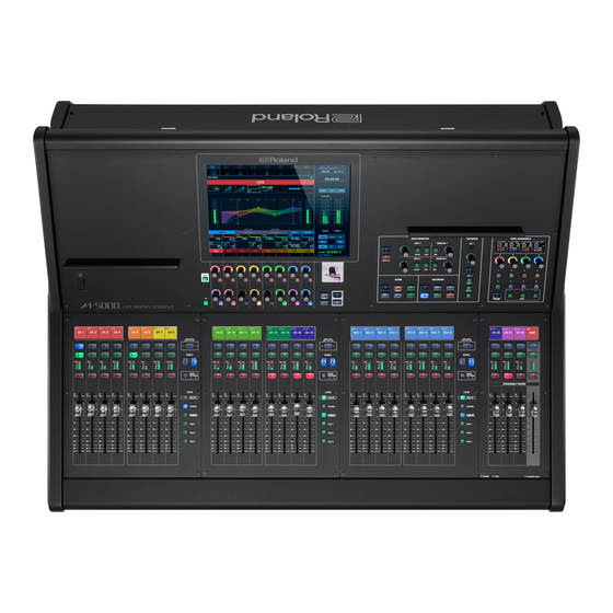
Roland M-5000 Reference Manual
Live mixing console
Hide thumbs
Also See for M-5000:
- Quick start manual (68 pages) ,
- Reference manual (230 pages) ,
- User manual (27 pages)
Table of Contents
Advertisement
Quick Links
Download this manual
See also:
User Manual
Advertisement
Table of Contents

Related Manuals for Roland M-5000


Summary of Contents for Roland M-5000
- Page 1 Reference Manual Ver.1.10 Before using the M-5000 / M-5000C, ensure that its system program is at the most recent version. For information on available upgrades for the system program, see the Roland website. Copyright © 2015 ROLAND CORPORATION...
-
Page 2: Organization Of The Documentation
Les éléments qui concernent spécifiquement l'un ou l'autre modèle sont indiqués par le terme « M-5000 uniquement » ou « M-5000C seulement ». Lorsque « le M-5000 est décrit » ou toute mention similaire apparaît, la description se réfère au M-5000 pour présenter à la fois le M-5000 et le M-5000C. -
Page 3: Table Of Contents
Utilisation de l’attache du cordon d'alimentation Using the Power-cord Hook Connecting Backup Power to the M-5000 Utilisation du Crochet du cordon d’alimentation Raccordement d’une alimentation de secours au M-5000 Disconnecting Backup Power Turning the Power On and Off Turning the Power On Turning the Power Off Déconnexion de l’alimentation de secours... - Page 4 Restoring All Data in the M-5000 Mixing Engine Loading a Project File from a USB Flash Drive MIXER CONFIGURATION Window Formatting a USB Flash Drive on the M-5000 Displaying the MIXER CONFIGURATION Window Muting All Outputs Changing the Number and Type of Input Channels/Output Setting the Date and Time Buses, Etc.
- Page 5 Contents Top Panel (Fader Region) Patchbays PATCHBAY Window Fader Bank Section Displaying the PATCHBAY Window About the Fader Bank Section PATCHBAY Window CH Tab Layers PATCHBAY Window BUS Tab Scrolling PATCHBAY Window MISC Tab Fader Bank Display PATCHBAY Window INPUT Tab Basic Operations of Fader Bank Section PATCHBAY Window OUTPUT Tab Changing Layers...
- Page 6 Recalling a Scene Stored Before Changing the MIXER STEREO PHASER CONFIGURATION PITCH SHIFTER x2 Scene Section of the Top Panel Roland Vintage Effects Creating New Scenes and Adding Scenes RE-201 (Space Echo) Storing a Scene (by Overwriting) SRV-2000 (Digital Reverb)
- Page 7 Changing the REAC Port to Work with at the M-48 MENU Window MANAGER Window M-48 MANAGER Window MENU Window Making Settings for Output from the M-5000 to M-48 Units 204 Tips for Output Patchbay Settings Using a MATRIX Making Settings for the Output Patchbay/M-48 MATRIX INPUT Window...
- Page 8 Working with Projects RS-232C Window Saving a Project File Loading a Project File GP I/O and Foot Switches Formatting a USB Flash Drive on the M-5000 Function List Functions Assignable to GPI Connectors and FOOT SW 1/2 Initializing Mixer Parameter Jacks...
- Page 9 Contents Adjusting the Detection Position of the Touch Display Factory Reset Dimensions Block Diagram Block Diagram of Monitor Section Additional Features Currently Under Development...
-
Page 10: Main Features
So what do you think? It's clear that the M-5000 has an extremely powerful mixing engine. High Resolution All elements installed in the M-5000 operate at a sample rate of 96 kHz. Not only AD/DA but the mixing engine as well operates at 96 kHz. All effect algorithms operate at 96kHz. - Page 11 M-5000 Remote dedicated application. External Control With the M-5000's four input and 12 output GP I/O connectors, you can send and receive control signals to and from external devices. The M-5000 also provides four inputs for footswitch pedals.
- Page 12 The fader bank section, where 8 faders are provided, can also be used as independent sets of 8 faders or as interlinked sets of 16 or 24 faders. The decision on how to use the 24 controls can be made instantly, letting you operate the M-5000 and its huge mixing engine with optimal efficiency. You can also assign often-used input channels and output buses to the four assignable faders and display them on the top panel at all times.
-
Page 13: Update History
5 <ALL CH SEND POINTS> was added to the MENU window. installed. 0“MENU Window” (p. 195) Bug Fixes 5 In rare cases, the M-5000 becomes unstable when performing the following operations. 5 Scene NEW, STORE, DUPLICATE, LOCK, SKIP, or RECALL PARAMETER change... -
Page 14: Quick Start
Quick Start First we’ll take a look at how to install the unit, part names and functions, an overview of operations, and other such information. The content of this chapter is the same as the Quick Start document packed with the unit. This chapter is organized into the following sections. -
Page 15: Placement And Setup
The items included with the M-5000 are as follows. Check to ensure that all are present. 5 Power cord * Be sure to use only the power cord included with the M-5000. 5 REAC connector covers (3) 5 Ferrite cores (6) -
Page 16: Detaching The Reac Caps
Placement and Setup Detaching the REAC Caps Connecting the Power Cord By default, the REAC ports are fitted with REAC caps. Remove NOTE these REAC caps when you use the REAC ports. Be careful to not Be sure to use the included power cord for connecting the lose the removed REAC caps so you can insert them again when power supply. -
Page 17: Retrait Des Caches Reac
Installation et ConfigurationRetrait des caches Retrait des caches REAC Connexion du cordon d'alimentation Par défaut, les ports REAC sont pourvus de caches REAC. Retirez ces NOTE caches REAC lorsque vous utilisez les ports REAC. Veillez à ne pas Veillez à utiliser le cordon d'alimentation fourni pour brancher égarer les caches REAC qui ont été... -
Page 18: Using The Power-Cord Hook
Insert the DC OUTPUT plug on the S-240P into the adapter cable (Speakon end). Twist the S-240P's DC OUTPUT plug clockwise until you hear it click. Insert the adapter cable (XLR4 end) into the EXT. POWER DC INPUT connector on the M-5000 until you hear it click. -
Page 19: Utilisation Du Crochet Du Cordon D'alimentation
Tourner la fiche DC OUTPUT du S-240P dans le sens des aiguilles d’une montre jusqu'à ce que vous entendiez un déclic. Insérer le câble de l'adaptateur (extrémité XLR4) dans le connecteur EXT. POWER DC INPUT du M-5000 jusqu'à ce que vous entendiez un déclic. -
Page 20: Disconnecting Backup Power
Turn off the power to the external power unit connected to the EXT. POWER DC INPUT connector on the M-5000. * If an external power Unit is providing power to the M-5000, the M-5000 will keep operating even if the power switch is in the OFF position. -
Page 21: Déconnexion De L'alimentation De Secours
(extrémité Speakon). 0 “Muting All Outputs” (p. 63) Baisser la sortie et éteindre l'alimentation de tout appareil raccordé à la sortie audio du M-5000 ou de toute unité d'entrée/sortie. Éteindre l'unité d'alimentation externe branchée sur le connecteur EXT. POWER DC INPUT du M-5000. -
Page 22: Replacing The Internal Lithium Battery
Be careful to avoid cutting your hand when opening. Attach the BATTERY panel and secure it in place using the screw loosened in step 3. Turn on the power to the M-5000 and set the date and time. 0“Setting the Date and Time” (p. 63) Restoring All Data in the M-5000 0“Restoring All Data in the M-5000”... -
Page 23: Remplacement De La Pile Au Lithium Interne
0“Restoring All Data in the M-5000” (p. 62) interne Fixation des housses de tablette Le M-5000 est équipé d'une pile interne au lithium qui maintient la fonction d'horloge de l’unité et conserve les réglages de la console. Fixez les housses de tablette aux endroits indiqués ci-dessous. Ils Si la pile est déchargée, la fonction d'horloge et de récupération des... -
Page 24: Installing An Expansion Interface (Option)
* When restarting the unit with the expansion interface installed, wait for about one second before you turn on the power. Turn off the power to the M-5000 and unplug the power cord from the power outlet. Loosen the mounting screws (2) for the expansion slot specified in the figure, then detach the panel. -
Page 25: Installation D'un Module D'interface (En Option)
Installation d'un module d'interface indiqué sur l’illustration. (en option) Vous pouvez étendre les capacités d'entrée et de sortie du M-5000 en installant dans le logement d'expansion de l'unité un module d'interface vendu séparément. Pour plus d'informations sur les modules d'interface qui peuvent être installés dans le M-5000, veuillez consulter le site Web Roland... -
Page 26: Installing Reac Devices
5 Never wind (bend) an Ethernet cable using a coil radius of 25 original digital audio-transmission technology using Ethernet. It uses a protocol independently developed by Roland based on millimeters or less, or bend the cable sharply enough to kink it. -
Page 27: Connecting Reac Input/Output Units
MASTER MASTER M-5000 CLOCK SOURCE: INTERNAL The input/output units connected to the REAC A and B ports and the default input/output patchbays on the M-5000 are as follows. Input port Input channel REAC A INPUT 1–24 CH 1–24 REAC B INPUT 1–24 CH 25–48... -
Page 28: Part Names And Functions
Part Names and Functions Top Panel M-5000... -
Page 29: Talkback Section
Part Names and Functions M-5000C Fader Bank Section Monitor Section This section is for working with input channels and output buses in This section is for working with and controlling the monitor busses. 0“Monitor Section” (p. 33) sets of eight. You use the layer buttons and scroll buttons to access the desired input channel or output bus. -
Page 30: Fader Bank Section
Part Names and Functions Fader Bank Section This section is for working with eight input channels or output buses or both. You use layer selection and scrolling to access the desired input channel or output bus. Fader Bank display [FUNC] button [SEL] button [SOLO] button [SCROLL K] /... -
Page 31: Assignable Fader Section
Flash Drive on the M-5000” (p. 63), it is not possible to use this USB flash drive on the M-5000. 5 The M-5000 supports only USB flash drives (USB flash Memory and USB memory). USB Hard Disk and Memory Card Readers are not supported. -
Page 32: Display Section
Part Names and Functions Display Section This section lets you display and work with mixer parameters, system settings, and other values. For details, refer to the "Operation of the touch display" section in the Reference Manual (PDF). Touch display Selected knob / button [SHIFT] button [SCROLL H]/ [SCROLL I] button... -
Page 33: Monitor Section
Part Names and Functions Monitor Section This section is for working with monitor functions. This unit is provided with two monitor systems. The available selections for MONITOR 1 are 5.1, STEREO, and NONE (no assignment), and the available selections for MONITOR 2 are STEREO and NONE (no assignment). -
Page 34: Scene Section
Part Names and Functions Scene Section This section is for working with scene memories. Scene memory is a function that lets you store and recall mixing parameters as “scenes. ” [SELECT H]/ [SELECT I] button [STORE] button [DISP] button [RECALL] button [NEW] button Name Description... -
Page 35: Talkback Section
Part Names and Functions Talkback Section This section is for working with talkback functions. TALKBACK MIC 1 [LEVEL] knob [DISP] button [TALK 1]–[TALK 3] button Name Description TALKBACK MIC 1 This is the internal microphone for talkback. [LEVEL] knob This adjusts the level of talkback. [DISP] button This displays the TALKBACK/OSC window. -
Page 36: User-Assignable Section
Part Names and Functions User-assignable Section This section is for assigning and working with parameters of your choosing. User-assignable display [A]–[D] knob [ 1 ] –[8] buton [BANK 1]– [DISP] button [BANK 3] button Name Description User-assignable display This displays the parameters assigned to assignable knobs/buttons. [A]–[D] knob These manipulate the assigned parameter value. -
Page 38: Rear Panel
Part Names and Functions Rear Panel M-5000 19 20 M-5000C LAMP Connectors These are XLR-4-31 connectors that supply power to third-party gooseneck lamps. DC+12V [DC+12V/500mA] POWER Switch This turns the power on and off. 0“Turning the Power On and Off” (p. 20) NOTE If you need to turn off the power completely, first turn off the unit, then unplug the power cord from the power outlet. -
Page 39: Panneau Arrière
Noms et fonctions des différentes parties Panneau arrière M-5000 19 20 M-5000C Connecteurs LAMP Ce sont les connecteurs XLR-4-31 qui alimentent les lampes à col de cygne tierces. DC+12V [DC+12V/500mA] Commutateur d’alimentation POWER Permet de mettre sous ou hors tension. -
Page 40: Midi Connectors
Power is not supplied if the device is not compatible with REAC * Pins 7 and 8 are connected inside the M-5000. EMBEDDED POWER. * For the M-5000 to function, the three pins RXD, TXD, and GND must be connected as shown in the figure. - Page 41 Vous pouvez utiliser ce connecteur RS-232C pour contrôler le M-5000 à distance via un périphérique externe. Il sert à connecter un iPad via le câble dock fourni avec le M-5000. Synchronisation Start-Stop (mode asynchrone), Cela vous permet d'utiliser l'appareil à distance et d'effectuer Méthode de transmission...
-
Page 42: Ground Terminal
Cooling Fan you intend to use by referring to the manual that came with it. This is the fan for cooling the M-5000. When placing the M-5000, be (This instrument’s phantom power: DC+48 V, 14 mA Max) careful not to obstruct the ventilation holes. - Page 43 Logement BATTERY connecter. Ce logement contient une pile au lithium qui fait fonctionner l'horloge du M-5000 et conserve les réglages de la console. Si la pile est déchargée, elle doit être remplacée. 0“Remplacement de la pile au lithium interne” (p. 23)
-
Page 44: Front Panel
Part Names and Functions Front Panel PHONES 1/2 Jacks These are jacks for connecting headphones. You can use them to monitor MONITOR 1 or MONITOR 2 audio. Two outputs are provided: miniature stereo phone type and stereo 1/4-inch phone type. Ensure that the total impedance of both is less than 16 ohms. -
Page 45: Panneau Avant
Noms et fonctions des différentes parties d’autres appareils qui ne nécessitent pas une telle alimentation. Assurez-vous de vérifier les spécifications de tout microphone que vous souhaitez utiliser en vous référant au manuel qui l’accompagne. (Alimentation fantôme de cet instrument : DC+48 V, 14 mA Max) EXPANSION SLOT Cet emplacement sert à... -
Page 46: Overview Of Operations
Basic Operations of Fader Bank Section Fader Bank Section Changing Layers On the M-5000, operations are carried out using groups of eight faders. Each set of eight faders is called a “fader bank. ” Press a layer button to switch to the desired layer. -
Page 47: Anchor Channels
Overview of Operations Anchor Channels Accessing Adjacent Anchor Channels Pressing and holding the [SCROLL K] or [SCROLL J] button scrolls You can mark channels you want to access rapidly in the various forward or backward to the anchor channel nearest the currently layers. -
Page 48: Isolated Banks
8 DCA faders, and 8 other input-channel faders. 8 INPUTS 8 DCA 8 INPUTS (The M-5000 is depicted.) Isolating a Fader Bank Unisolating a Fader Bank At the desired fader bank, press the [ISOLATE] button to Press the [ISOLATE] button to turn it off (dark). -
Page 49: Basic Touch Operations
The following four operations are used when working with the touch display. The configuration of the mixing engine in the M-5000 can be changed as you like to suit the desired purpose. This section describes selecting a mixer configuration from templates. -
Page 50: Home Screen
Overview of Operations HOME Screen Access the CH EDIT window The HOME screen appears at startup. On the HOME screen, tap areas are shown below. INPUT DYNAMICS 1 DYNAMICS 2 DYNAMICS 1 MISC DYNAMICS 2 When other window is displayed, to close the window and display the HOME screen, press the [VIEW] button. -
Page 51: Selecting The Source For An Input Channel
Overview of Operations Selecting the Source for an Input Channel Selecting the Destination for an Output Access the CH EDIT window for the desired input channel. 0“Access the CH EDIT window” (p. 50) Access the CH EDIT window for the desired output bus. Tap the <INPUT tab>. -
Page 52: Turning Phantom Power On Or Off
Overview of Operations Turning Phantom Power On or Off Adjusting the Preamp Gain Access the CH EDIT window for the desired input channel. On the HOME screen, go to the knob-assign area and tap 0“Access the CH EDIT window” (p. 50) <GAIN>. -
Page 53: Applying Dynamics
Overview of Operations Applying Dynamics Using Faders to Adjust the Send Level to AUX (SENDS ON FADER) Access the CH EDIT window. 0“Access the CH EDIT window” (p. 50) Using SENDS ON FADER lets you use faders to adjust the send level to an AUX. -
Page 54: Sending To Subgroup/Mix-Minus
Overview of Operations Sending to SUBGROUP/MIX-MINUS Using an FX with Send/Return This sends an input channel to a SUBGROUP or MIX-MINUS. On the HOME screen, tap <FX>. Memo MIX-MINUS lets you mix a specific channel pulled from MAIN. By default, all input channels are sent with POST FDR (on), with only necessary channels turned off. -
Page 55: Inserting An Fx
Overview of Operations Tap <DESTINATION A> or <DESTINATION B>. Inserting an FX The DESTINATION popover appears. This inserts an FX at INSERT A or INSERT B on an input channel or output bus. INSERT A is inserted before dynamics and EQ, and INSERT B is inserted after dynamics and EQ. -
Page 56: Inserting A Geq
Overview of Operations On the HOME screen, tap <FX>. Inserting a GEQ This inserts a GEQ at INSERT A or INSERT B. INSERT A is inserted before the dynamics and EQ, and INSERT B is inserted after the dynamics and EQ. DYN/EQ EQ/DYN 4-BAND... -
Page 57: Linking Channels
Overview of Operations On the HOME screen, tap <GEQ>. Linking Channels You can link multiple input channels or output buses into up to 12 groups. The parameters of linked input channels or output buses are set to the same values. You can select the parameters to link. Press the [MENU] button. -
Page 58: Making Assignments To Dca/Mute Groups
Overview of Operations Making Assignments to DCA/MUTE Using Talkback Groups Go to the talkback section on the top panel and press the [DISP] button. In DCA groups, you manipulate the levels of all assigned input channels or output buses at one time. The TALKBACK/OSC window appears. -
Page 59: Using The Oscillators
Overview of Operations Select the output destination for TALK 1 to TALK 3. Scene memory Press one of the [TALK 1] through [TALK 3] buttons in the talkback section. Scene memory is a function that lets you store and recall mixing parameters as “scenes. -
Page 60: Recalling A Scene
The formats of playable WAV files are as follows. Playback is possible even if the sampling frequency of the WAV file differs from the M-5000’s sampling frequency. Sampling frequency: 96kHz, 48kHz, 44.1kHz A popup prompting you to confirm the operation is displayed. -
Page 61: Playback From A Usb Flash Drive
[ t ] button. The data in the M-5000 is saved as a project file. You back up the data in the M-5000 by saving the project file to a Go to the recorder section on the top panel and press the USB flash drive. -
Page 62: Restoring All Data In The M-5000
Restoring All Data in the M-5000 The data in the M-5000 is saved as a project file. You restore data to the M-5000 by loading a project file from a USB flash drive. Loading a Project File from a USB Flash Drive Press the [MENU] button. -
Page 63: Formatting A Usb Flash Drive On The M-5000
Muting All Outputs NOTE Performing initialization causes all data to be lost. This mutes all outputs at times such as when turning the M-5000’s Data that is needed can be saved to a USB flash drive. power on or off. -
Page 64: Fader Calibration
Overview of Operations Fader Calibration If the fader positions are no longer aligned with the index markings of the top panel, carry out fader calibration to adjust. Press the [MENU] button. On the MENU window, tap <SYSTEM>, then tap <FADER CALIBRATION>. -
Page 65: Touch Display Operations
Touch Display Operations This section and the following sections describe the M-5000 in detail as a reference manual. First, you’ll learn how to work with the touch display, where a large amount of information is shown. In this chapter, the explanations are organized into the following sections. -
Page 66: Touch Display Operations
Touch Display Operations Operating the Touch Display Organization of the Display Screen The following four operations are used when working with the touch display. Using your fingertip, you press and release an on-screen button, area, or other item. The display is composed of the following elements. 5 HOME screen Double-tap The HOME screen is the screen displayed at startup. -
Page 67: Home Screen
Touch Display Operations HOME Screen Windows The HOME screen appears at startup. Windows include the CH EDIT window and the GEQ window. You use them to perform such tasks as adjusting input channels and output buses and making various settings. Even when windows, popovers, or other elements are displayed, this screen is always displayed underneath. -
Page 68: Popovers
Touch Display Operations Popovers List Operations Popovers are views briefly displayed on-screen when you select Lists are sometimes displayed in windows. particular parameters. When a list is displayed you can select and manipulate multiple They are displayed mainly in cases of parameters that have three or elements. -
Page 69: Selecting And Moving Multiple List Items
Touch Display Operations Selecting and Moving Multiple List Items Selecting and Duplicating Multiple List Items For each list element you want to move, select its For each list element you want to duplicate, select its <CHECKBOX> to turn it on. <CHECKBOX>... -
Page 70: Selecting And Deleting Multiple List Items
Touch Display Operations Selecting and Deleting Multiple List Items Entering Numerical Values The following view is displayed when entering numerical values. For each list element you want to delete, select its <CHECKBOX> to turn it on. 1/2/4/8 These enter 1, 2, 4, or 8 into the value input area. Tapping the value input area displays a value input popover. -
Page 71: Entering Text
Touch Display Operations Entering Text When entering text, a screen keyboard like the one shown below is displayed. 0-9, A-Z, `-=[]\;' , ./ These input text. NEXT This jumps to text input for the next channel. When this is on, letters of the alphabet are input CAPS in upper case. -
Page 72: Interlinked Operation Of The Touch Display And Top Panel
Interlinked Operation of the Touch Display and Top Panel This interlinks the display section’s touch display and knob section Some windows lack a knob section area, and in such cases the knob or the touch display and selected knobs, achieving rapid operation. section of the top panel is dark and cannot be operated. -
Page 73: Control Using Selected Knobs/Buttons
Interlinked Operation of the Touch Display and Top Panel Control Using Selected Knobs/Buttons Tapping a parameter on the touch display shifts focus to the parameter. When a parameter has focus, you can use the selected knob and button to work with it. -
Page 74: [Shift] Button And [All] Button
Interlinked Operation of the Touch Display and Top Panel Memo [SHIFT] Button and [ALL] Button The way the [ALL] button is turned on and off changes depending to how you press the [ALL] button. When you release the button quickly after pressing it, it operates [SHIFT] Button as a toggle turning on or off with each press. -
Page 75: Configuring The Mixer
In this chapter, you’ll learn how to configure the mixing engine to match the situation. First we’ll take a look at the types of input channels and output buses you can select in the M-5000. After that, we’ll change the number of input channels and output buses and make settings for input and output patchbays. -
Page 76: Overview Of Input Channels/Output Buses
Overview of Input Channels/Output Buses Types of Input Channels/Output Buses You can select from among the following types of input channels and output buses for the M-5000’s mixing engine. Input channels 5 INPUT CHANNEL (MONO/STEREO) Output buses 5 MAIN (MONO/LR/LCR/CROSS-MATRIX LCR/5.1) -
Page 77: Input Channel
Overview of Input Channels/Output Buses INPUT CHANNEL INPUT CHANNEL processes audio from INPUT PATCHBAY and sends it to the output bus. Direct output to OUTPUT PATCHBAY is also possible. You can select MONO or STEREO. INPUT PATCHBAY MAIN (5.1, LCR o INPUT CHANNEL (MONO or STEREO) CH TOP DYN/EQ... -
Page 78: Main/Mix-Minus
With MIX MINUS, the send level from input channels, SUBGROUP, and AUX is identical with that of MAIN, but the setting to not send a specific channel can be made. You can select MONO or STEREO for MIX MINUS. This M-5000 is equipped with 2 MAINs. You can select from among MONO, LR, LCR, CROSS-MATRIX LCR, and 5.1. OUTPUT PATCHBAY MAIN (5.1, LCR or LR), MIX-MINUS (MONO or STEREO) -
Page 79: Subgroup/Aux
Overview of Input Channels/Output Buses SUBGROUP/AUX OUTPUT PATCHBAY MAIN (5.1, LCR or LR), MIX-MINUS (MONO or STEREO) DYN/EQ CH TOP POST D.GAIN PRE FDR POST FDR EQ/DYN SUBGROUP and AUX process audio sent from input channels, and output it to OUTPUT PATCHBAY. Output to MAIN, MIX MINUS, or MATRIX is also MAIN OUT possible. -
Page 80: Matrix
AUX OUT φ 4-BAND BUS TRIM D.GAIN DYN 1 DYN 2 DELAY FADER MUTE TO PATCHBAY TO MAIN (5.1, LCR, or LR) SOLO TO SOLO 1/2 EXPANSION SLOT (E) SOLO TO SOLO 1/2 5.1 SURROUND PAN KEY-IN FILTER 6, 3, 2 LCR PAN KEY-IN FILTER... -
Page 81: Changing The Number Of Input Channels/Output Buses
About the Unit’s Mixing Engine the Unit’s Mixing Engine The M-5000 is provided with internal audio paths for 128 channels. These paths can freely be used as either input channels or This section shows a number of mixer configurations that you can output buses. -
Page 82: Mixer Configuration Window
Changing the Number of Input Channels/Output Buses Changing the Number and Type of Input MIXER CONFIGURATION Window Channels/Output Buses, Etc. Changes in mixer configuration are made in the MIXER CONFIGURATION window. Changes in number and type are made in the MIXER CONFIGURATION window, using input channel/output bus list. - Page 83 Changing the Number of Input Channels/Output Buses MAIN SUBGROUP NUMBER NAME NONE No MAIN at all is used. Value input area MAIN 1: MONO MAIN 2: None MONO * One audio path is used. NUMBER SUBGROUP number MAIN 1: LR SUBGROUP name MAIN 2: None * When no specific name exists, a name...
- Page 84 Changing the Number of Input Channels/Output Buses MIX-MINUS NUMBER NAME NUMBER NAME Value input area Value input area NUMBER AUX number NUMBER MIX-MINUS number AUX name MIX-MINUS name * When no specific name exists, a name * When no specific name exists, a name NAME NAME corresponding to the AUX number (AUX xx) is...
- Page 85 Changing the Number of Input Channels/Output Buses MATRIX MONITOR NUMBER NAME NONE No monitors are used. Value input area Stereo STEREO * Two audio paths are used. LCR (stereo + center) Sets the number of input channels/output buses MATRIX INPUTS sent to MATRIX.
-
Page 86: Moving/Deleting Multiple Input Channels/Output Buses
Changing the Number of Input Channels/Output Buses Selecting a Mixer Configuration from a Template You use the TEMPLATE popover to load a preset mixer configuration template. Display the MIXER CONFIGURATION window. Tap <TEMPLATE>. The TEMPLATE popover is displayed. NONE No oscillator at all is used. Select a template for mixer configuration. -
Page 87: Mixer Configuration Templates
Changing the Number of Input Channels/Output Buses THEATER Mixer Configuration Templates Channel number Audio paths used Type CH 1-94 DEFAULT MONO MAIN 1 AUX 1-16 MONO Channel number Audio paths used Type MTX 1-8 MONO MON 1 STEREO CH 1-64 MONO Talkback CH 65-68... -
Page 88: Rearranging Input Channels/Output Buses
Rearranging Input Channels/Output Buses On this unit, you can freely rearrange the order of input channels Displaying the ARRANGE CHANNEL Window and output buses, even after applying the mixer configuration. Rebooting the console is not necessary. Go to the display section and press the [MENU] button. ARRANGE CHANNEL Window The MENU window appears. -
Page 89: Patchbays
Patchbays After establishing the mixer configuration, you can then route your PATCHBAY Window CH Tab inputs and outputs in the patchbays. Patchbay operations are carried out mainly in the PATCHBAY In the PATCHBAY window CH tab, you make patchbay settings for window. -
Page 90: Patchbay Window Bus Tab
Patchbays MAIN (5.1, LCR or LR), MIX-MINUS (MONO or STEREO) DYN/EQ CH TOP POST D.GAIN PRE FDR POST FDR EQ/DYN POST FDR TO MAIN (5.1, LCR, or LR) PATCHBAY Window BUS Tab PATCHBAY Window MISC Tab 4-BAND φ 5.1 SURROUND PAN FADER MUTE BUS TRIM... -
Page 91: Patchbay Window Input Tab
In the PATCHBAY window INPUT tab, you can list the input- In the PATCHBAY window OUTPUT tab, you can list the output- connector settings for input and output devices connected to the connector settings for input and output devices connected to the M-5000. M-5000. NUMBER/TYPE NUMBER/TYPE... -
Page 92: Popover For Making Patchbay Settings
Patchbays Assigning a Range of Channels in a Patchbay Popover for Making Patchbay Settings You can assign a range of channels for a patchbay. When you select an input connector, output connector, input channel, output bus, or other such element, a popover like the one Example: This assigns inputs connectors 1 through 24 on an S-2416 shown below appears. -
Page 93: Using Alternate Input Connectors
Usage Example 2) Recording is performed on a multi-track recorder, and at rehearsal the following day, the recording data is played- back to the M-5000 and mixed. The recording mic is set to IN and the output from the multi-track recorder is set to TR. IN and TR are switched together. -
Page 94: Setting All Input Channels To Alternate Input Connectors
Patchbays Setting All Input Channels to Alternate Input Connectors On the PATCHBAY window CH tab, tap <SWAP INPUT>. Tap the header of the IN, ALT, or TR column. The input connectors for all input channels are switched. -
Page 95: Input Channel And Output Bus Operations
Input Channel and Output Bus Operations The chapters up to now have shown you how to configure the mixer differently according to circumstances. Now, in this chapter, we’re ready to do some mixing! Adjusting EQ, dynamics, send level, and other such parameters for input channels and output buses is accomplished mainly on the HOME screen and the CH EDIT window. -
Page 96: Home Screen
HOME Screen When the M-5000 starts up, the HOME screen (Process View) is Channel Strips displayed. You can display information for any eight channels you choose on the HOME screen. Pressing the [SEL] buttons on the top panel lets The channel strips displayed on the HOME screen show information you access input channels and output buses quickly. -
Page 97: Channel Strip (Input Channel)
HOME Screen Channel Strip (Input Channel) Input patchbay Input patchbay Meter INPUT DYNAMICS 1 Meter DYNAMICS 2 MISC SENDS INPUT PAN/ROUTING PAN/ROUTING Knob section Knob section area area NAME NAME DCA/MUTE GROUP DCA/MUTE GROUP Process view Meter view Input patchbay Displays the channel number and input source as set in the patchbay. -
Page 98: Channel Strip (Output Bus)
HOME Screen Channel Strip (Output Bus) Output patchbay Output patchbay Meter Meter DYNAMICS 1 DYNAMICS 2 MISC PAN/ROUTING PAN/ROUTING Knob section Knob section area area NAME NAME DCA/MUTE GROUP DCA/MUTE GROUP Process view Meter view Output patchbay Displays the channel number and output destination as defined in the patchbay. Displays the signal level. -
Page 99: Channel Strip (Dca)
HOME Screen Channel Strip (DCA) DCA group number Input channel/output bus list RECALL SAFE NAME DCA group number Displays the number of the DCA group. Displays a list of input channels/output buses assigned to the DCA group. Input channel/output bus list Tapping displays the ASSIGN TO DCA popup. -
Page 100: Copying/Pasting Input Channel/Output Bus Settings On The Home Screen
HOME Screen Copying/Pasting Input Channel/Output Bus Settings on the HOME Screen Copying Input Channel/Output Bus Settings on the HOME Screen Go to the display section and press the [MENU] button. The MENU window appears. Tap <COPY>. Tap <COPY>. The selected setting is saved to the clipboard. Pasting Input Channel/Output Bus Settings on the HOME Screen Go to the display section and press the [MENU] button. - Page 101 HOME Screen Tap <PASTE>. The setting is pasted. Memo To undo (cancel) the last paste operation, go to the MENU window and tap <UNDO PASTE>.
-
Page 102: Ch Edit Window
CH EDIT Window You perform operations on input channels and output buses in the Switching the Input Channel/Output Bus CH EDIT window. Displayed in the CH EDIT Window Displaying the CH EDIT Window To switch the input channel or output bus displayed in the CH EDIT window, go to the HOME screen and tap the channel strip you want to switch. -
Page 103: Layout Of The Ch Edit Window
CH EDIT Window Layout of the CH EDIT Window CH EDIT Window (Input Channel) Channel name/channel color INPUT Tab In the INPUT tab, you make input patchbay settings, preamp settings, and other such settings. Display area 5 Channel name/channel color CH TOP meter Displays the signal level at CH TOP. -
Page 104: Dynamics Tab
CH EDIT Window Using Alternate Input Connectors DYNAMICS Tab You can set three types of input connectors for input channels In the DYNAMICS tab, you make the settings for Dynamics 1 and 2. --- IN, ALT (alternative), and TR (track) --- and switch between these The operation procedures for Dynamics 1 and Dynamics 2 are the according to circumstances during use. -
Page 105: Parameter Area Of The Dynamics Tab
CH EDIT Window GATE Memo The isolation point for the key-in signal is as follows. Key-in signal Isolation point SELF Signal input to Dynamics Input channel CH TOP Output bus POST FADER Memo With MAIN, only SELF can be selected for the key-in signal. MEMO The level detection points for INPUT METER, OUTPUT METER, and GR METER are as follows. -
Page 106: Eq Tab
CH EDIT Window COMPRESSOR EQ Tab In the EQ tab, you make the settings for HPF, LPF, and 4-BAND EQ. Memo The order in which the DYNAMICS 1/2 tabs and the EQ tab are displayed depends on the routing of DYNAMICS 1/2 and EQ as set in the DYNAMICS window. -
Page 107: Misc Tab
CH EDIT Window You perform the following operations in the parameter area. MISC Tab In the MISC tab, you make a variety of settings, such as Delay, Direct Out, Channel Safe, Solo, and Insert. LO TYPE LM TYPE HM TYPE HI TYPE HPF/LPF HPF/LPF center frequency... -
Page 108: Sends Tab
The available DELAY UNIT values are msec, Meter, Feet and In the SENDS tab, you make the settings for sendings for input Frame (24, 25, 29.97, or 30 fps). Delay on the M-5000 is based channels to AUX. on msec steps, and simply changing the DELAY UNIT parameter SENDS overview does not alter delay times in msecs. - Page 109 CH EDIT Window Parameter Area of the SENDS Tab ALL CH SEND POINTS Window In the ALL CH SEND POINTS window, you set send points to an AUX for all input channels at one time. SEND PAN PAN LINK Send point Send level Send pan to AUX SEND PAN...
-
Page 110: Pan/Routing Tab
CH EDIT Window PAN Tab (LR) PAN/ROUTING Tab The further tabs are displayed on the PAN/ROUTING tab. 5 PAN tab This sets panning when sending to MAIN. 5 SUBGROUP tab This sets assignments to SUBGROUPs. 5 MIX-MINUS tab This is displayed using the input channel, AUX, and SUBGROUP. PAN Tab Operations The operation procedures in the PAN tab differ according to the setting for MAIN that has been made in the MIXER CONFIGURATION... - Page 111 CH EDIT Window PAN Tab (LCR/CROSS-MATRIX LCR) LCR PAN When this is on, the signals sent to MAIN LCR can be collectively turned on/off. Pan will operate across the MAIN LCR and CENTER is displayed. When this is off, the signals sent to MAIN LR and MAIN C can be individually turned on/off.
- Page 112 CH EDIT Window PAN Tab (5.1) Divergence Divergence adjusts the amount of diffusion along the respective axes (front X axis, rear X axis, or Y axis). For example, setting FRONT DIV, REAR DIV, and F/R DIV all to “0%” and placing the signal directly above L outputs the audio only to L, with nothing output to other channels (C, R, Ls, LFE, and Rs).
-
Page 113: Dca/Mute Group Tab
CH EDIT Window DCA/MUTE GROUP Tab In the DCA/MUTE GROUP tab, you assign input channels and output buses to DCA and MUTE groups DCA 1 - DCA 24 Assigns to the DCA group. MUTE 1 - MUTE 8 Assigns to the MUTE group. CLEAR Clears all assignments to DCA/MUTE groups. -
Page 114: Ch Edit Window (Output Bus)
CH EDIT Window CH EDIT Window (Output Bus) MISC Tab In the MISC tab, you make a variety of settings, such as Delay, Channel Safe, Solo, and Insert. OUTPUT Tab In the OUTPUT tab, you make output patchbay settings. Input channels are not displayed. -
Page 115: Pan/Routing Tab
CH EDIT Window PAN/ROUTING Tab The PAN/ROUTING tab is displayed for SUBGROUP and AUX, and you can make settings for sending to MAIN and sending to MIX- MINUS. The operation procedures are the same as for the CH EDIT window PAN/ROUTING tab for input channels. -
Page 116: Copying/Pasting Input Channel/Output Bus Settings At The Ch Edit Window
CH EDIT Window Pasting Input Channel/Output Bus Settings at Copying/Pasting Input Channel/Output the CH EDIT Window Bus Settings at the CH EDIT Window Display the CH EDIT window where you want to paste. Copying Input Channel/Output Bus Settings at Go to the display section and press the [MENU] button. the CH EDIT Window The MENU window appears. -
Page 117: Top Panel (Fader Region)
Top Panel (Fader Region) This chapter describes operation procedures for the lower half of the top panel, the fader region. In particular, mastering use of the fader bank section, one of this unit’s strong points, will let you accomplish quick level adjustment with very little body movement. -
Page 118: Fader Bank Section
On the M-5000, operations are carried out using groups of eight faders. Each set of eight faders is called a “fader bank. ” The M-5000 provides three fader banks. You can operate the respective fader banks in an interlinked way or independently, enabling you to carry out your intended operations instantly. -
Page 119: Layers
Fader Bank Section Layers Basic Operations of Fader Bank Section Each fader bank has two basic layers (CHANNEL and DCA/BUS) and three customizable layers (USER 1 through 3) that you can switch Changing Layers between according to purpose. Press a layer button to switch to the desired layer. Layer button Description [CHANNEL]... -
Page 120: Isolated Banks
Fader Bank Section Isolated Banks A fader bank whose [ISOLATE] button has been turned on is called an “isolated bank. ” Using isolated banks makes it possible to configure a wide variety of fader layouts, such as arranging the CHANNEL layer and DCA/BUS layer side by side at the same time. [ISOLATE] Term Description... -
Page 121: Anchor Channels
Fader Bank Section Press the [SEL] button that corresponds to the desired Anchor Channels anchor channel. You can mark channels you want to access rapidly in the various layers. These are called “anchor channels. ” Specifying anchor channels in the respective layers lets you quickly jump to the desired channel. -
Page 122: Listing Channels Assigned To A Dca Group (Spill Dca)
Fader Bank Section Listing Channels Assigned to a DCA Group Using Faders to Adjust the Send Level to (SPILL DCA) AUX (SENDS ON FADER) Using SPILL DCA lets you take input channels and output buses Using SENDS ON FADER lets you use faders to adjust the send level assigned to a DCA group and temporarily expand them into a to AUX. -
Page 123: Select Aux Sends Window
Fader Bank Section SELECT AUX SENDS Window Tapping <AUX TARGET> displays the SELECT AUX SENDS window. * This is not displayed when no AUX exists. Selects the AUX selected in the knob section area of the HOME screen. Also simultaneously selects AUXes accessed when SENDS ON FADER was on. -
Page 124: Operation Procedures In The Function Mode
“ASSIGN FADER” appears when you select the [USER 1] - [USER 3] layers or assignable faders. The M-5000 switches to the mode for making the settings for the selected function. Operate the fader bank to access the desired input channel or output bus. -
Page 125: Canceling Channel Assignments To Faders
Repeat steps 3 and 4. MEMO You can assign up to 64 input channels and output buses to The M-5000 switches to the UNASSIGN FADER mode. each of USER 1 through 3 layers. Press the [SEL] button for the fader whose assignment Press the [FUNC] button to exit the Function mode. -
Page 126: Setting An Anchor Channel
Select “SET ANCHOR”. (Press the corresponding [SEL] button.) The M-5000 switches to the SET ANCHOR mode. Press the [SEL] button for the fader which you want to set an anchor to apply a check mark (ASSIGN )). Press the [FUNC] button to exit the Function mode. -
Page 127: Assignable Fader Section
Assignable Fader Section About the Assignable Fader Section You can assign any four channels to the assignable fader section. This lets you keep important channels displayed on the top panel at all times. It can be handy to assign channels that you always want instant access to, such as MASTER, main vocals, and MC mic. Fader Bank display [SEL] button [SOLO] button... -
Page 128: Assigning Channels To Faders
“UNASSIGN FADER” appears when you select the [USER 1] - [USER 3] layers or assignable faders. layers or assignable faders. The M-5000 switches to the ASSIGN FADER mode. The M-5000 switches to the UNASSIGN FADER mode. Press the [SEL] button for the fader whose assignment Press the [SEL] button for the fader whose assignment you want to change to apply a check mark (ASSIGN )). -
Page 129: Switching The Home Screen/Ch Edit Screen
HOME screen or CH EDIT screen, you use the [SEL] buttons on or assignable fader section. the top panel. When the M-5000 starts up, the channel strip for the leftmost fader bank section is displayed. The CH EDIT window for the selected input channel or output bus appears. -
Page 130: When The Ch Edit Screen Is Displayed
Switching the HOME Screen/CH EDIT Screen When the CH EDIT Screen Is Displayed Press an unselected [SEL] button. The CH EDIT window for the selected input channel or output bus appears. Press the selected [SEL] button. The CH EDIT window disappears and the HOME screen appears. -
Page 131: Sidebar
Sidebar The sidebar for the HOME screen is always displayed and never hidden, even when various windows are displayed. Important information that you want to monitor at all times and buttons for accessing important screens are displayed here. In this chapter, the explanations are organized into the following sections. 5 “Sidebar”... -
Page 132: Sidebar
Sidebar Displays the meter bridge About the Sidebar 0“Overviewing Meters/Faders” (p. 134) Indicate the communication status of the REAC ports and EXPANSION SLOTs. REAC/SLOT The right side of the HOME screen is called the "sidebar." 0“Checking the REAC Port and EXPANSION indicators SLOT Communication Status”... -
Page 133: Changing What The Peak/Rms Meter Displays
Sidebar Changing What the PEAK/RMS Meter Displays On the PEAK/RMS meter on the sidebar, you can select and display any two from among MAIN 1, MAIN 2, MONITOR 1, and MONITOR 2. To change what is displayed, tap the PEAK/RMS meter. -
Page 134: Overviewing Meters/Faders
Overviewing Meters/Faders Meter Bridge On the Meter Bridge, you can overview all meters and faders for input channels and output buses. SETUP Tapping this displays the METER SETUP popover. Exits the Meter Bridge. Displaying the Meter Bridge To display the Meter Bridge, go to the sidebar and tap <I>. METER SETUP Popover In the METER SETUP popover, you make settings for meters. -
Page 135: Date And Time
DATE & TIME Window You use the DATE & TIME window to set the date and time on the M-5000. To display the DATE & TIME window, go to the HOME screen and tap the <Date/time area>. Selects from among the following date formats. -
Page 136: Knob-Assign Area
Knob-assign Area Assigns the following parameters to the upper About the Knob-assign Area portion of the knob section area of the HOME screen. Knob: Preamp gain The portion of the sidebar shown below is called the "knob-assign Button: PAD GAIN area."... -
Page 137: User Selectable Popover
Knob-assign Area USER SELECTABLE Popover Tapping <USER SELECTABLE> displays the USER SELECTABLE popover. To assign a parameter selected using the USER SELECTABLE popover to the knob section area, go to the knob-assign area and tap <USER>. Selects the following parameters. Knob: HPF frequency Button: HPF ON/OFF Selects the following parameters. -
Page 138: Effects
Effects About Effects FX RACK Window The M-5000 is provided with eight stereo effect systems. In the FX RACK window, you make settings for effect input/output, effect type, and the like. The settings for FX 1-8 are displayed in a row. -
Page 139: Displaying The Fx Rack Window
Effects Displaying the FX RACK Window Effect Library (Preset) To display the FX RACK window, go to the HOME screen and tap <FX>. Effect type TYPE 0“About Effect Types” (p. 142) Effect library number Effect library name NAME Tapping this selects the effect library. RECALL Recalls the selected library data. -
Page 140: Fx Edit Window
Effects Displaying the FX EDIT Window FX EDIT Window To display the FX EDIT window, go to the FX RACK window and tap In the FX EDIT window, you work with advanced parameters for the <FX OVERVIEW>. respective effects. The layout of the FX EDIT window varies according to effect type, but the general layout is as shown below. -
Page 141: Inserting An Fx
Effects Inserting an FX Display the CH EDIT window. 0“CH EDIT Window” (p. 102) Tap the <MISC tab>. MISC tab INSERT A INSERT B Tap <INSERT A> or <INSERT B>, then select the number of the FX to insert. Memo If the input channel or output bus is stereo, you can make insertions at the following four locations. -
Page 142: About Effect Types
About Effect Types REVERB Tab This section covers the 22 high-quality effect types you can select on the M-5000. Reverb STEREO REVERB Input L Output L Stereo 4 Band EQ Reverb Input R Output R Type of reverb This is a stereo-in, stereo-out reverb. It adds reverberation without 5 ROOM1 impairing the position of the sound image that’s been set for the... -
Page 143: Reverb
About Effect Types EQ Tab REVERB Input L Output L 4 Band EQ Gate Reverb Key-In Input R Output R This is a mono-in, stereo-out reverb. It provides a gate that can be used for gating or ducking, allowing you to cut the reverb during its decay, or to cut the reverb when the level of the original sound is high. - Page 144 About Effect Types EQ Tab GATE Tab LO TYPE LM TYPE HM TYPE HI TYPE GATE ON Turns the gate on/off GATE: Sound lower than the THRESHOLD level will be attenuated by the amount specified by EQ ON Turns the EQ on/off RANGE FREQ Center frequency...
-
Page 145: Delay
About Effect Types LONG DELAY Delay Input L Output L DELAY x2 Input A Output A Delay FEEDBACK PRE DPF Delay LEVEL WET POSITION POST DPF Input R Output R Input B Output B This is a mono-in, stereo-out long delay. PRE DPF Delay WET POSITION... -
Page 146: Multi Tap Delay
About Effect Types LEVEL Tab MULTI TAP DELAY Input L Output L Pan 1 Pan 2 Pan 12 Multi Tap Delay FEEDBACK LEVEL Input R Output R LEVEL 1-12 Level of the delay sound This is a mono-in, stereo-out twelve-stage tap delay. PAN Tab When MULTI TAP DELAY is selected, four tabs are displayed. -
Page 147: X.mod Delay
About Effect Types FEEDBACK Tab X.MOD DELAY Input L Output L PRE DPF POSITION Delay L POST DPF Modulation POST DPF POSITION Delay R PRE DPF Input R Output R This is a stereo-in, stereo-out cross-modulation delay. Time until the delayed sound is returned to the FB TIME input of the delay Amount of delayed sound returned to the input... -
Page 148: Modulation
About Effect Types STEREO FLANGER Modulation In modulation-type effects, raising the feedback value will make the DIR SW Input L Output L sound richer and more spacious. Negative values will invert the phase. EFF SW STEREO CHORUS Flanger L DIR SW Input L Output L Flanger R... -
Page 149: Stereo Phaser
About Effect Types STEREO PHASER PITCH SHIFTER x2 DIR SW Input L Output L Input A Output A Pitch Shifter EFF SW Phaser L Input B Output B Pitch Shifter Phaser R EFF SW This is a dual-mono pitch shifter. The operation procedures for A and B are the same. -
Page 150: Roland Vintage Effects
(non-linear) mode in which the reverb sound is cut off according to the gate time setting. This is a delay that models the Roland RE-201 Space Echo. The original was mono-in, mono-out, but this modeling adds PAN HEAD SHORT/MIDDLE/LONG settings and a REVERB STEREO Sw, allowing When SRV-2000 is selected, two tabs are displayed. -
Page 151: Sde-3000 X2 (Digital Delay)
The lower and upper limits of the value will differ depending on <MODE> and <REV SEL>. This is a delay that models the Roland SDE-3000 digital delay. The original unit was mono-in, mono-out, but this modeling provides a NON LNR mode: -.9-99s dual-mono configuration with two such units in parallel. -
Page 152: Dimension D Chorus)
About Effect Types SDD-320 (Dimension D Chorus) SPH-323 x2 (Phase Shifter) This is a stereo-in, stereo-out chorus that models the Roland SDD- This is a phase shifter that models the Roland SPH-323 Phase 320 Dimension D. Shifter. The original was mono-in, mono-out, but this modeling is a dual-mono design with two units in parallel. -
Page 153: Stereo Flanger)
About Effect Types SBF-325 (Stereo Flanger) BOSS Compact Pedal Effects This is a stereo-in, stereo-out flanger that models the Roland SBF- 325 Stereo Flanger. CE-1 (Chorus Ensemble) This is a chorus modeled on the Boss CE-1 Chorus Ensemble. The original has mono in and mono out (or wet/dry out) -
Page 154: X2 (Digital Delay)
About Effect Types DD-3 x2 (Digital Delay) DM-3 x2 (Delay) This is a delay modeled on the Boss DD-3 Digital Delay. This is a delay modeled on the Boss DM-3 Delay. The original has mono in and mono out (or delay/direct out) The original has mono in and mono out (or delay/direct out) specifications, but the modeling has dual mono specifications that specifications, but the modeling has dual mono specifications that... -
Page 155: Multiband Dynamics
About Effect Types ENHANCER Tab MULTIBAND DYNAMICS This regularizes the volume level for separate bands (low, midrange, and high). When MASTERING is selected, six tabs are displayed. EQ Tab ENHANCER ON Enhancer on/off SENS Amount of enhancer effect Frequency at which application of the enhancer FREQ effect starts Volume level of enhancer sound... - Page 156 About Effect Types EXPANDER Tab LIMITER Tab EXPANDER ON Expander on/off LIMITER ON Limiter on/off Interval until application of the expander Suppresses prominent distortion when extreme SOFT CLIP ATTACK effect starts after the input level falls below the compressor/limiter effect is applied threshold level Interval until application of the limiter effect Interval until application of the expander effect...
-
Page 157: Dynamic Eq
About Effect Types DYNAMIC EQ This applies a compressor or expander around a specific frequency. You can make settings for four bands each for A and B. The operation procedures for A and B are the same. MEMO The center-frequency setting ranges for each band are as follows. -
Page 158: Geq
About GEQs GEQ EDIT window (GEQ) This M-5000 is equipped with 32 GEQ (graphic equalizer) systems In the GEQ EDIT window, you make settings for GEQ input and (monaural). Any one of them can be configured as output, parameters, and other such values. Some parts displayed in... -
Page 159: Displaying The Geq Edit Window
Displaying the GEQ EDIT Window Operating a GEQ Using the Knob Section To display the GEQ EDIT window, go to the HOME screen and tap Use <GEQ SEL 1> through <GEQ SEL 32> to select a GEQ <GEQ>. to work with. Use <GEQ OVERVIEW>... -
Page 160: Operating A Geq Using The Faders (Geq On Fader)
Use the faders to work with the range you selected in step Operating a GEQ Using the Faders (GEQ ON FADER) Use <GEQ SEL 1> through <GEQ SEL 32> to select a GEQ to work with. Memo When a fader is at a position other than 0 dB, the corresponding Set <ON FADER>... -
Page 161: Returning Geq Settings To Their Default Values
Returning GEQ Settings to Their Default Values Making a GEQ Group When you assign several GEQs to a GEQ group, the GEQs assigned Use <GEQ SEL 1> through <GEQ SEL 32> to select a GEQ to the same GEQ group have the same settings. to work with. -
Page 162: Copying/Pasting Geq Settings
Use <GEQ SEL 1> through <GEQ SEL 32> to select the GEQ Copying/Pasting GEQ Settings where you want to paste the settings. Use <GEQ SEL 1> through <GEQ SEL 32> to select a GEQ to copy. Go to the MENU window and tap <PASTE GEQ>. Go to the display section and press [MENU] button. -
Page 163: Geq Edit Window (Peq)
You perform the following operations in the parameter area. GEQ EDIT Window (PEQ) Some parts displayed in the window are different when the system is set to PEQ. GEQ SEL 1-32 MORE TYPE TYPE TYPE TYPE FREQ Center frequency Sharpness of the frequency-response curve TYPE Displays the Filter Type Selection popover. -
Page 164: Operating A Peq Using The Knob Section
Operating a PEQ Using the Knob Section Use <GEQ SEL 1> through <GEQ SEL 32> to select a GEQ to work with. Use <BAND 1-4> or <BAND 5-8> to select the range to work with using the knobs. Use the knob section to work with the range you selected in step 2. -
Page 165: Top Panel (Display Region)
Top Panel (Display Region) This chapter describes how to use the controls arranged in the upper half of the top panel, in the display region. In this chapter, the explanations are organized into the following sections. 5 “User-assignable Section” (p. 166) 5 “Monitor/Solo”... -
Page 166: User-Assignable Section
User-assignable Section Operate the knob or button to which you want to assign a About the User-assignable Section parameter. The user-assignable section has four knobs and eight buttons, which you can assign to parameters of your choosing and display on the top panel. The user-assignable section also has three banks, letting you work with more parameters by switching among them. -
Page 167: User Assignable Window
User-assignable Section Press the [DISP] button. USER ASSIGNABLE Window Pressing the [DISP] button in the user-assignable section displays the USER ASSIGNABLE window. In the USER ASSIGNABLE window, you can change the LABELs (parameter names) and knob or button colors shown on the user- assignable display, and clear parameter assignments. -
Page 168: User-Assignable Section Of The Top Panel
User-assignable Section User-assignable Section of the Top Panel This section is for assigning and working with parameters of your choosing. User-assignable display [A]–[D] knob [ 1 ] –[8] buton [BANK 1]– [DISP] button [BANK 3] button Name Description User-assignable display This displays the parameters assigned to assignable knobs/buttons. -
Page 169: Monitor/Solo
“Monitor” is a function that takes an input channel or output bus selected as the monitor source and outputs it to an output connector or headphones for monitoring. The M-5000 is equipped with a monitor function that supports up to 5.1 channels, for an extremely high degree of freedom. -
Page 170: Monitor/Solo Block Diagram
Monitor/Solo Monitor/Solo Block Diagram SOLO PATCHBAY SOLO 1 SOLO 1 L TRIM SOLO 1 R SOLO 1 ENABLE TB RTN MONITOR 1 (5.1 MODE) MONITOR 1 TB / GPI KNOB / FADER LEVEL ALIGNMENT LISTEN MODE MON 1 L φ MUTE DELAY LEVEL... -
Page 171: Monitor Window
Monitor/Solo TRIM Adjusts the solo level. You can register 18 input channels/output buses you want to input to a monitor. This selects one of those and sends it to the monitor. SOURCE SELECTOR Output-bus monitoring uses the POST FDR signal, and input-channel monitoring uses the CH TOP signal. Selects from among the following as the mode for monitor output. -
Page 172: Displaying The Monitor Window
Monitor/Solo Displaying the MONITOR Window MONITOR 1/2 SETUP Window To display the MONITOR window, go to the monitor section on the top panel and press the [DISP] button. MON 1/MON 2 Tabs Turning this on outputs SOLO 1/2 to MONITOR MIX SOLO 1/2 1/2. -
Page 173: Solo Tab
Monitor/Solo Selecting the Monitor Source Displayed for SOURCE SOLO Tab SELECTOR In the MONITOR 1/2 SETUP window, tap <SOURCE SELECTOR ASSIGN> for the setting you want to change. Press the [SEL] button for the input channel or output bus you want to set. Tapping <CLEAR>... -
Page 174: Headphones Tab
Monitor/Solo HEADPHONES Tab MUTE Mutes headphones. Turns dimmer on/off. Lowers and outputs headphones output by the amount set using <DIM LEV>. Selects the headphones source from among the following. 5 MON 1 HP SOURCE 5 MON 2 When selected MON1 or selected MON2 is set to NONE, MAIN is set to the headphones source. -
Page 175: Monitor Section Of The Top Panel
Monitor/Solo Monitor Section of the Top Panel You can use the top panel’s monitor section to operate monitors. Number Name Description [DISP] button This displays the MONITOR window. This turns Solo in Place on and off. To turn on Solo in Place, press and hold this button for 2 seconds. It flashes when on. -
Page 176: Scene Memory
0“Selected Scene, Current Scene” (p. 180) Scene memory is a function that lets you store mixer parameters as a scene, and recall them when desired. On the M-5000, you can Tapping the scene area displays the SCENE window. store up to 300 scenes. -
Page 177: Mixer Parameters Stored In Scenes
Scene Memory Mixer Parameters Stored in Scenes Scene Section of the Top Panel The following parameters are stored in scenes. [SELECT H]/ 5 Input patchbay [SELECT I] button 5 Output patchbay 5 Preamp settings (including input/output units) 5 INPUT CHANNEL 5 MAIN [STORE] button [DISP] button... -
Page 178: Storing A Scene (By Overwriting)
Scene Memory Memo Storing a Scene (by Overwriting) Newly created or added scenes are each automatically given a scene number (having up to two digits to the right of the decimal point). Go to the scene section on the top panel and press the [SELECT H] or [SELECT I] button to select the number of If no next scene exists, the scene is created and given a scene number equal to the number of the selected scene plus one. -
Page 179: Scene Window
Scene Memory Press the [RECALL] button. SCENE Window The scene is recalled. You organize and manage scene memories in the SCENE window. Displays the GLOBAL SCOPE window. In the GLOBAL SCOPE window, you specify the GLOBAL SCOPE range to recall for all scene memories. 0“GLOBAL SCOPE Window”... -
Page 180: Selected Scene, Current Scene
Scene Memory Selected Scene, Current Scene Prohibiting Editing for the Scene (Lock) Locked scenes cannot be stored, deleted or renamed. To turn on lock for a scene, go to the SCENE window and tap <LOCK>. LOCK CURRENT SCENE PREV SCENE SELECTED SCENE NEXT SCENE The scene previous to the currently selected... -
Page 181: Global Scope Window
Scene Memory GLOBAL SCOPE Window RECALL PARAMETER Window In the GLOBAL SCOPE window, you set the recall range for all scene In the RECALL PARAMETER window, you set the recall range for memories. individual scenes. To display the GLOBAL SCOPE window, go to the SCENE window To display the RECALL PARAMETER window, go to the SCENE and tap <GLOBAL SCOPE>. -
Page 182: Recall Parameter List
Scene Memory DCA/BUS tab Recall Parameter List The further tabs are displayed on the DCA/BUS tab. To set a range to recall, using Recall parameter list. 5 DCA The information displayed changes as shown below depending on what tab has been selected at the GLOBAL SCOPE window or 5 MAIN RECALL PARAMETER window. -
Page 183: Interlinking Scene Memories With Other Devices (Events)
Scene Memory FX/GEQ/INS tab Interlinking Scene Memories with Other Devices (EVENTS) The further tabs are displayed on the FX/GEQ/INS tab. 5 FX 5 GEQ You can use the GP I/O connector, FOOT SW 1/2 jacks, and MIDI 5 INSERT connectors to interlink scene memories to other devices. 5 Recalling a scene on reception from the GPI connector or FOOT Channel number/Channel name SW 1 or 2 jack... -
Page 184: Assigning Scenes To Gpi Connectors And Foot Sw 1/2 Jacks
Scene Memory Select the MIDI data. Assigning Scenes to GPI Connectors and FOOT SW 1/2 Jacks This assigns a scene to a GPI connector or FOOT SW 1 or 2 jack. Tap <EVENTS> for the scene you want to assign to the connector. -
Page 185: Settings The Midi Out Connector
Scene Memory Select the input waveform to detect. Tap <APPLY>. This makes scene recall occur when the specified waveform is input. Settings the MIDI OUT Connector This specifies the MIDI OUT connector to output a signal on recall. Tap <EVENTS> for the scene you want to assign to the connector. -
Page 186: Setting A Gpo Connector
Interlinking with M-48 Memory This specifies the GPO connector to output a signal on recall. When an M-5000 scene memory is recalled, you can simultaneously also recall an M-48 memory. Tap <EVENTS> for the scene you want to assign to the connector. -
Page 187: Usb Memory Recorder
* Before using USB flash drives for this unit, please format the USB Song list flash drives on this unit. 0“Formatting a USB Flash Drive on the M-5000” (p. 233) WAV File Formats The formats of recordable WAV files are as follows. -
Page 188: Song List
USB Memory Recorder Song list Turning on the checkbox lets you delete WAV files. CHECKBOX (You can not select multiple items.) The sequence in which WAV files are played back (alphabetical order) NAME WAV file name LENGTH WAV file length (time) FORMAT WAV file format MODIFIED... -
Page 189: Recording/Playback To/From A Usb Flash Drive
USB Memory Recorder Playback from a USB Flash Drive Recording/Playback to/from a USB Flash Drive Go to the recorder section on the top panel and press the [DISP] button. The RECORDER window appears. Recording to a USB Flash Drive Tap <PLAYBACK>. The DESTINATION popover appears. -
Page 190: Talkback/Oscillator
The following two tabs appear. performers, stage managers, or staff. The M-5000 has three talkback systems, TALK 1 through 3, and each can individually be assigned to Here you make settings for talkback and talkback different outputs and set on or off. -
Page 191: Talkback/Osc Window Talkback Tab
Talkback/Oscillator TALKBACK RETURN TALKBACK/OSC Window TALKBACK Tab TALKBACK INPUT METER Input-connector input level Selects the input connector to use for talkback RETURN MIC return. +48V Turns input-connector phantom power on/off. These send talkback to the output destinations HPF slope characteristics assigned to TALK 1 through TALK 3. -
Page 192: Talkback/Osc Window Osc Tab
Talkback/Oscillator TALKBACK/OSC Window OSC Tab Talkback Section of the Top Panel TALKBACK MIC 1 [LEVEL] knob [DISP] button PINK Outputs pink noise from the oscillator. [TALK 1]-[TALK 3] WHITE Outputs white noise from the oscillator. button SINE Outputs a sine wave from the oscillator. Outputs a 31-band multi-sine wave from the MULTI oscillator. - Page 194 MENU Window Up to this point we have covered basic mixing operations. The M-5000 has a variety of other functions as well, and you access these from the MENU window. The MENU window is the gateway to expansive functions. In this chapter, the explanations are organized into the following sections.
-
Page 195: Menu Window
Settings at the CH EDIT Window” (p. 116) 0“Copying/Pasting GEQ Settings” (p. 162) UNDO Clears the level meter’s peak hold or “over” PEAK CLEAR indication. SECURITY Locks the M-5000, preventing operation. 0“Locking the Console to Prevent Operation” LOCK CONSOLE (p. 223) -
Page 196: Using A Matrix
Using a MATRIX MATRIX processes audio sent from input channels and output Tapping an individual element lets you manipulate the following buses, and outputs it to OUTPUT PATCHBAY. parameters using the selected knob/button. In the MATRIX INPUT window, you select input channels or output Send level buses to send to MATRIX and adjust the send levels. -
Page 197: Adjusting The Send Level To Matrix
Using a MATRIX Adjusting the Send Level to MATRIX Tap <IN 1> through <IN (n)>, then select the input channel or output bus you want to input to MATRIX. Tap the location where the desired MATRIX column and the desired input channel/output bus row intersect. In the top panel’s display section, press the selected button to turn on sending to MATRIX. -
Page 198: Mute Groups
To display the MUTE GROUP MASTER window, go to the MENU window and tap <MUTE GROUP>. NAME MUTE GROUP LIST Mutes all outputs of the M-5000 and input/ MUTE ALL OUTPUTS output units. Displays the MUTE GROUP name and MUTE GROUP color. -
Page 199: Control
When the sampling rate is set at 96 kHz, the number of audio channels that a REAC slave device present at the REAC port where the M-48 is connected can send to the M-5000 is 32. Sending 33 or more channels produces noise. - Page 200 Connection Producing No Noise 1 (OK) Set the system’s sampling rate at 48 kHz. S-4000S-4000 S-4000S-4000 REAC SLAVE /40ch/96kHz REAC SLAVE /40ch/48kHz M-48 M-48 S-4000D S-4000D REAC A MASTER REAC A MASTER M-5000 96kHz M-5000 48kHz REAC MASTER REAC MASTER...
- Page 201 M-48 is connected, and so no noise is produced. S-4000S-4000 S-4000S-4000 REAC SLAVE REAC SLAVE /40ch/96kHz /40ch/96kHz M-48 M-48 S-4000D S-4000D REAC A REAC B REAC A (or B) REAC SPLIT/BACKUP MASTER MASTER MASTER M-5000 96kHz M-5000 96kHz REAC MASTER REAC MASTER...
-
Page 202: Listing Connected M-48 Units (M-48 Manager Window)
Listing Connected M-48 Units (M-48 M-48 MANAGER Window MANAGER Window) Tap <REAC SELECT> and change the REAC port to work with at the M-48 units connected to the M-5000 are listed in the M-48 M-48 MANAGER window. MANAGER window. REAC SELECT... - Page 203 (MEMORY) RECALL specified memory number for all units on the M-48 list. Settings are recalled from each M-48. This disables operations to mute connected M-48 (MUTE) DISABLE units made from the M-5000. Muting is ended for units that are already muted.
-
Page 204: Making Settings For Output From The M-5000 To M-48 Units
40-channel Source at the M-48 MANAGER Window M-5000 to M-48 Units The M-48 functions as a REAC SPLIT device, and mixes the M-5000’s At the M-48 MANAGER window, tap <SETUP SOURCES>. output patchbays as a 40-channel source. To change the M-48’s... -
Page 205: Copying And Pasting Settings At The M-48 Manager Window
M-48 Control Pasting M-48 Settings Copying and Pasting Settings at the M-48 MANAGER Window At the M-48 list, select the M-48 you want to paste to. Copying M-48 Settings At the M-48 list, select the M-48 you want to copy from. Tap <PASTE>. -
Page 206: Pasting Settings To Multiple M-48 Units
M-48 Control Pasting Settings to Multiple M-48 Units Making Settings for Each M-48 (M-48 SETUP Window) At the M-48 list, select <CHECKBOX> for each M-48 you want to paste to. For a M-48, you use the M-48 SETUP window to make settings. Displaying the M-48 SETUP window To display the M-48 SETUP window, go to the M-48 MANAGER window, and at the M-48 list, tap <SETUP>... -
Page 207: M-48 Setup Window
These change what information is shown in the display area. 5 OVERVIEW tab This lets you list source levels and make group mixes. You can use the faders on the M-5000 to manipulate the source levels. 5 SOURCE LEV/PAN tab Here you make settings for source levels, panning, and sending to AUX. - Page 208 This lets you list source levels and make group mixes. Here you make LEVEL, PAN, and TO AUX settings for sources 1 through 40, and specify assignments to groups. Turning <ON FADER> on lets you use the M-5000’s faders to work with the source levels. SOURCE OVERVIEW...
-
Page 209: Assign Tab
M-48 Control ASSIGN Tab PREFERENCES Tab Here you assign sources 1 through 40 to groups 1 through 16. Here you make preference settings for M-48 units. GROUP SOURCE CLEAR This clears all assignments of sources to groups. When this is on, only the sources assigned to MIX ONLY SOLO groups are mixed at the M-48 units. -
Page 210: Copying And Pasting Settings At The M-48 Setup Window
M-48 Control Pasting M-48 Settings Copying and Pasting Settings at the M-48 SETUP Window Display the M-48 SETUP window for the M-48 you want to paste to. Copying M-48 Settings Tap <MORE>. MORE Display the M-48 SETUP window for the M-48 you want to copy from. -
Page 211: Making Leds Flash To Identify M-48 Units
M-48. Memo The M-48 specified as the Engineer Monitor is stored in the M-5000’s system settings, and can be saved in a project file. Initializing the M-5000’s system settings clear the Engineer Monitor settings. Loading system settings from an M-5000 project file re-creates the Engineer Monitor settings. -
Page 212: Selecting The M-48 To Use As An Engineer Monitor
M-48 Control Selecting the M-48 to Use As an Engineer UNIT NAME M-48 unit name This accesses the M-48 ENGINEER’S MONITOR Monitor SETUP window. SETUP 0“Engineer Monitor Feature” (p. 211) This cancels application of the Engineer Monitor RELEASE feature to the M-48. Display the M-48 MANAGER window. -
Page 213: Selecting The M-48 To Replicate Using The Engineer Monitor Feature
M-48 Control M-48 SETUP Window Selecting the M-48 to Replicate Using the Engineer Monitor Feature At the M-48 SETUP window, you select the musician’s M-48 you want to replicate using the Engineer Monitor feature. Display the M-48 SETUP window for the M-48 whose mix M-48 MANAGER Window you want to check. -
Page 214: Remote Control Of An M-48 From The M-48 Set As The Engineer Monitor
M-48 Control Remote Control of an M-48 from the M-48 Set Engineer Monitor Settings (M-48 ENGINEER’S As the Engineer Monitor MONITOR SETUP Window) You can perform remote operations on the group mix of a You use the M-48 ENGINEER’S MONITOR SETUP window to make musician’s M-48 from the Engineer Monitor M-48. -
Page 215: M-48 Internal Memory
M-48 Control Storing the Mixer Settings of All M-48 Units in M-48 Internal Memory Memory (M-48 MANAGER Window) The M-48 saves the current mixer settings in “current memory. ” The M-48 has 16 memory areas for storing current memory. You use the M-48 MANAGER window to store in memory the mixer The following information is saved in memory. -
Page 216: Recalling The Mixer Settings Of All M-48 Units From Memory (M-48 Manager Window)
Recalling the Mixer Settings of All M-48 Units Saving Settings of an Entire M-48 from Memory (M-48 MANAGER Window) You can save the settings of an entire M-48 on the M-5000 or a USB flash drive. You use the M-48 MANAGER window to recall from memory When saving the settings on the M-5000, you use M-48 libraries. -
Page 217: M-48 Libraries
M-48 Control M-48 Libraries M-48 Library Popover You use the M-48 Library popover to perform operations on M-48 libraries. Displaying the M-48 Library popover. Display the M-48 SETUP window for the M-48 whose library you want to work with. Tap <MORE>. A popover appears. -
Page 218: Storing Settings In An M-48 Library
By default, the project file is saved in the following directory on the From the M-48 library list, select the number for the store flash drive. operation. /ROLAND/M-48/PROJ SAVE M-48 PROJECTS Window You use the SAVE M-48 PROJECTS window to save M-48 project files on a USB flash drive. -
Page 219: Saving M-48 Projects
M-48 Control M-48 List Saving M-48 Projects M-48 project files are saved with file names in the following format. “unit-number_unit-name.M48PJ” CHECKBOX Display the SAVE M-48 PROJECTS window. At the M-48 list, turn on <CHECKBOX> for the M-48 units whose projects you want to save. Checkbox Turning on the checkbox lets you save M-48 CHECKBOX... -
Page 220: Load M-48 Projects Window
M-48 Control M-48 Project File List LOAD M-48 PROJECTS Window You use the LOAD M-48 PROJECTS window to load M-48 projects DIRECTORY from a USB flash drive. You can load different projects to multiple M-48 units. CHECKBOX To display the LOAD M-48 PROJECTS window, go to the M-48 MANAGER window and tap <MORE>, then tap <LOAD M-48 PROJECTS>. -
Page 221: Loading M-48 Projects
M-48 Control MEMO Loading M-48 Projects When you want to execute automatic assignment from the file names of the M-48 project files, tap <AUTO ASSIGN>. Display the LOAD M-48 PROJECTS window. M-48 project files saved with file names in the following format are automatically assigned to M-48 units that have the same At the M-48 project file list, go to the folder containing the unit names. - Page 222 M-48 Control To accept the assignments of M-48 project files, tap <LOAD>. A popup prompting you to confirm the operation is displayed. Tap <OK>. A progress bar appears, and the M-48 project files assigned to the M-48 units are loaded. When the message “COMPLETED”...
-
Page 223: Locking The Console To Prevent Operation
Locking the Console to Prevent Operation You can lock the console to prevent it from being operated. Unlocking the Console Memo If you turn off the power while the console is locked, the console To unlock the console, tap <UNLOCK>. is unlocked the next time you turn on the power. -
Page 224: Setup Window
SETUP Window In the SETUP window, you can display screens for making configuration settings for the M-5000, such as changing the mixer configuration, organizing and managing projects, and initializing the unit. In this chapter, the explanations are organized into the following sections. -
Page 225: Setup Window
SETUP Window To display the SETUP window, go to the MENU window and tap <SETUP>. 0“MENU Window” (p. 194) Displays the MIXER CONFIGURATION window. MIXER 0“Changing the Number of Input Channels/ CONFIGURATION Output Buses” (p. 81) Displays the ARRANGE CHANNEL window. 0“Rearranging Input Channels/Output Buses”... -
Page 226: Inserting External Effects Devices
LEVEL TO PATCHBAY You can connect external effects devices to input and output connectors on the M-5000 and on input and output units connected to the M-5000, and insert the devices into input channels, output buses, and monitors. You make the settings for inserting external effects devices in the INSERT SETTINGS window. - Page 227 Inserting External Effects Devices Use <SEND> or <RETURN> to adjust the input or output level as needed. Tap the parameter you want to work with, then use the selected knob/button to manipulate it. Tap <INSERT>, then select the input channel, output bus, or monitor for inserting the external effects device.
-
Page 228: Channel Link
Channel link is a function that makes specific input channels or buses specified for a single channel link. output buses have the same parameters. PREAMP Preamp settings The M-5000 has 12 channel links. FILTER HPF, LPF DYN 1 Dynamics 1(Excludes the key-in) - Page 229 Channel Link Press the [SEL] button for the input channel or output bus you want to assign to the channel link. The input channel or output bus is assigned to the channel link. From the parameter list, select the parameters to link. Tap <OK>.
-
Page 230: Projects
About Projects The data saved in projects is sectionalized as shown below, and you The settings you create by operating the M-5000 are stored in the can manage the data by section. unit as project data. You can save and organize these on a USB flash drive as project files (file extension: m5pj). -
Page 231: Project Window
0“Entering Text” (p. 71) SIZE Sizes of the project files Formats the USB flash drive. 0“Formatting a USB Flash Drive on the M-5000” Date and time when the project file was last FORMAT MODIFIED edited (p. 233) Loads a project file. -
Page 232: Working With Projects
Projects Loading a Project File Working with Projects You load project files from a USB flash drive. When you load a file, you can select individual sections of data to Saving a Project File load. Display the PROJECT window. You save project files on a USB flash drive. When you save a file, the data in all categories is saved. -
Page 233: Formatting A Usb Flash Drive On The M-5000
Projects Formatting a USB Flash Drive on the M-5000 Display the PROJECT window. Tap <FORMAT>. A popup prompting you to confirm the operation is displayed. Tap <FORMAT>. Formatting of the USB flash drive starts. -
Page 234: Initializing Mixer Parameter
INPUT CH PATCH Input channel patchbay NOTE BUS PARAMETER Bus parameter BUS PATCH Bus patchbay Never turn off the power to the M-5000 before initialization All mixer settings finishes. 5 Patchbay 5 Input channels 5 Output buses 5 Effects 5 GEQs... -
Page 236: System Window
SYSTEM Window In the SYSTEM window, you can display screens for changing the M-5000’s system settings. In this chapter, the explanations are organized into the following sections. 5 “SYSTEM Window” (p. 237) 5 “Changing the Preferences for the User Interface” (p. 238) 5 “Adjusting the Brightness of the Top Panel and Touch Sensitivity”... -
Page 237: System Window
SYSTEM Window In the SYSTEM window, you can display screens for changing the Displays the PREFERENCES window. M-5000’s system settings. Here you can change your preferences for the PREFERENCES user interface. To display the SYSTEM window, go to the MENU window and tap 0“Changing the Preferences for the User... -
Page 238: Changing The Preferences For The User Interface
When this is on, a confirmation popup appears PATCHBAY CHANGE when you change the input/output patchbay. BUTTON When the [SOLO] button is pressed, the [SEL] follows [SOLO] M-5000 behaves as if the [SEL] button was also simultaneously pressed. -
Page 239: Adjusting The Brightness Of The Top Panel And Touch Sensitivity
Adjust SENSITIVITY until you achieve the intended touch detection. Memo Depending on the environment where the M-5000 is used, fader touch sense may fail to function effectively, leading to incorrect fader operation (especially during times of high humidity). At such times, press <CALIBRATE TOUCH SENS>. -
Page 240: Other Options
Other Options In the OPTION window, you make settings for other options. OPTION Window To display the OPTION window, go to the SYSTEM window and tap <OPTION>. CH-MUTE OPTION When an input channel is muted, sends to AUX AUX SENDS are also muted. -
Page 241: Downmix Settings
In the DOWNMIX SETTINGS window, you can specify a factor for downmixing from a large number of channels to a smaller number of channels. The M-5000 performs downmixing in a wide variety of situations. For example, downmixing is done when monitoring 5.1 channels or LCR using headphones. -
Page 242: Settings For The Word Clock
The word clock is a synchronizing signal for digital-audio signals. Display the WORD CLOCK window. This is used in the M-5000’s internal digital signal processing and in the transmission of digital-audio signals between devices. Tap <SAMPLING FREQ> and select a sampling frequency. -
Page 243: Reac Applications And Expansion Slot Settings
The REAC mode determines how the REAC devices transmit audio original digital audio-transmission technology using Ethernet. It signals over the network. uses a protocol independently developed by Roland based on REAC modes are of the following three types. Ethernet technology, and makes possible transmission of 40 input... -
Page 244: Reac Splitters
REAC Applications and EXPANSION SLOT Settings REAC Splitters REAC Ports on the M-5000 You can connect a MASTER device to a REAC splitter and divide This unit has two REAC ports: A and B. The SPLIT/BACKUP port can (split) the audio signal from MASTER to multiple SPLIT units. -
Page 245: Increasing The Number Of Reac Ports
REAC Applications and EXPANSION SLOT Settings Increasing the Number of REAC Ports REAC / SLOT Window If more transmission paths are needed than the unit’s REAC ports To display the REAC / SLOT window, go to the SYSTEM window and provide, install an optional “XI-REAC”... -
Page 246: Slot D Tab/Slot E Tab
REAC Applications and EXPANSION SLOT Settings XI-DANTE SLOT D Tab/SLOT E Tab The information shown below is displayed when an XI-DANTE is You use the SLOT D tab and SLOT E tab to make settings for installed in an expansion slot. EXPANSION SLOT D and E. - Page 247 REAC Applications and EXPANSION SLOT Settings XI-MADI The setting items shown below are displayed when an XI-MADI is installed in the expansion slot. STATUS STATUS Displays the link status of the MADI IN 1/2 connector. 5 LINKED: Linked normally 5 LINKING: Establishing a connection, or STATUS the unit’s sampling rate differs from the input signal.
-
Page 248: Midi
In the MIDI window, you make settings for MIDI and USB MIDI. To display the MIDI window, go to the SYSTEM window and tap <REMOTE>, then tap <MIDI>. Sets the M-5000’s device ID. DEVICE ID This is setting is shared by MIDI and USB MIDI. -
Page 249: Rs-232C
RS-232C RS-232C Window In the RS-232C window, you set the communication speed for the RS-232C interface. To display the RS-232C window, go to the SYSTEM window and tap <REMOTE>, then tap <RS-232C>. Selects the RS-232C communication speed from among the following. 5 4.8k bps 5 9.6k bps 5 14.4k bps... -
Page 250: Gp I/O And Foot Switches
GP I/O and Foot Switches You use the GP I/O connector and the FOOT SW 1 and 2 jacks to GP I/O Connector Hardware Specifications send and receive control signals to and from external devices. Function List GP I/O Connector This is a D-sub 25-pin connector (4 in/12 out) for sending and receiving control signals to and from an external device. -
Page 251: Gpi Connectors
5 V. 1,000 mA. Be careful not to exceed this value. FOOT SW 1/2 Jacks Vmax +5V Switches can be detected at the FOOT SW 1 and 2 jacks. M-5000 M-5000 FOOT SW 1/2 TIP FOOT SW 1/2 RING Vmax +5V FOOT SW 1 and 2 are also balanced 1/4”... -
Page 252: Input/Output Waveforms
GP I/O and Foot Switches NEG LEVEL Input/Output Waveforms INPUT Input Waveforms NEG EDGE DETECT POS LEVEL INPUT POS EDGE DETECT NEG PERIOD Output Waveforms POS PULSE POS PERIOD NEG PULSE POSITIVE Inactive Active NEGATIVE Inactive Active... -
Page 253: Gpi/O / Foot Sw Window
GP I/O and Foot Switches NEG LATCH GPI/O / FOOT SW Window Press+Release Press+Release You use the GPI/O / FOOT SW window to assign functions to the GP I/O connector and the FOOT SW 1 and 2 jacks. To display the GPI/O / FOOT SW window, go to the SYSTEM window Inactive Active Inactive... -
Page 254: Gpi / Foot Sw Tab
GP I/O and Foot Switches GPI / FOOT SW Tab Assigning Functions to GPI Connectors and FOOT SW Jacks You use the GPI / FOOT SW tab to assign functions to the GPI connectors and the FOOT SW 1 and 2 jacks. 0“Assigning Functions to GPI Connectors and FOOT SW Jacks”... -
Page 255: Gpi / Foot Sw Tab Parameter Area
GP I/O and Foot Switches TALK GPI / FOOT SW Tab Parameter Area This turns talkback on or off. The values that you can set in the parameter area differ according to the assigned function. RECALL SCENE This recalls a specified scene. You use the SCENE window to specify the scene number. -
Page 256: Fader Level
This operates the volume control connected to the GPI connector from the minimum value to the maximum value. Tap <OK>. This sets the minimum value measure by the M-5000 to <MIN LEVEL> and the maximum measured value to <MAX LEVEL>. -
Page 257: Gpo Tab
GP I/O and Foot Switches Selecting the Fader for Applying a Function GPO Tab This selects the fader for applying AUDIO FOLLOW VIDEO or FADER You use the GPO tab to assign functions to GPO connectors. LEVEL. 0“Assigning Functions to GPO Connectors” (p. 258) Tap <TARGET>. -
Page 258: Assigning Functions To Gpo Connectors
GP I/O and Foot Switches Assigning Functions to GPO Connectors GPO Tab Parameter Area The values that you can set in the parameter area differ according Display the GPI/O / FOOT SW window GPO tab. to the assigned function. Select the connector number where you want to assign SCENE RECALL the function. - Page 259 GP I/O and Foot Switches FADER START FADER ON This outputs a pulse signal when the specified fader exceeds a This outputs a continuous signal from when the specified fader specified value. exceeds the “on” level until it falls below the “off” level. This displays the channel where FADER START is This displays the channel where FADER ON is applied.
- Page 260 GP I/O and Foot Switches Selecting the Fader for Applying a Function This selects the fader for applying FADER START, FADER STOP, or FADER ON. Tap <TARGET>. A popup for selecting the fader appears. This clears the fader where FADER LEVEL is CLEAR currently applied.
-
Page 261: Fader Calibration
Fader Calibration If the fader positions are no longer aligned with the index markings of the top panel, carry out fader calibration to adjust. Press the [MENU] button. On the MENU window, tap <SYSTEM>, then tap <FADER CALIBRATION>. The FADER CALIBRATION window appears. Tap an item from <-INF>... -
Page 262: Updating The Unit
When expansion ends, a folder containing the updater appears. Copy the updater to the root directory of a USB flash drive. Start the M-5000 and insert the flash drive into its USB MEMORY connector. In the SYSTEM window, tap <UPDATE>. -
Page 263: Viewing The Information About The Unit
Status of the lithium battery LITHIUM BATTERY The voltage is displayed in parentheses. SIDE FAN Status of the cooling fan on the side of the M-5000 INSIDE FAN Status of the cooling fan inside the M-5000 LICENSE License information of software... -
Page 264: Data
Data... -
Page 265: Main Specifications
5 OUTPUT jacks (M-5000: 1–16, M-5000C: 1-8): XLR-3-32 type Outputs (balanced) M-5000: Max 296 (96 kHz), Max 456 (48 kHz / 44.1 kHz) 5 PHONES 1 jack: Stereo 1/4 inch phone type M-5000C: Max 288 (96 kHz), Max 448 (48 kHz / 44.1 kHz) - Page 266 * In the interest of product improvement, the specifications and/ or appearance of this unit are subject to change without prior Recommended Load Impedance notice. 5 OUTPUT jacks (M-5000: 1–16, M-5000C: 1-8): 10 k ohms or greater 5 PHONES jacks (1, 2): 32 ohms or greater Minimum Load Impedance 5 PHONES jacks (1, 2): 16 ohms Nominal Output Level (ty.)
-
Page 267: Connecting To Your Computer Via Usb
In order to connect to your computer via USB, you must first install the USB driver in your computer.The M-5000’s dedicated driver can be downloaded from the Roland website. Refer to the Roland website for details on the operating requirements. -
Page 268: Adjusting The Detection Position Of The Touch Display
Adjusting the Detection Position of the Touch Display If the detection position of tap operations is inaccurate depending on the person operating the touch display or the location of the operation, use the following method to adjust the detection position. Hold down the [MENU] and [VIEW] buttons in the top panel’s display section and turn on the power. -
Page 269: Factory Reset
Factory Reset This initializes the M-5000, returning it to its factory-default state. NOTE Performing initialization causes all data to be lost. Data that is needed can be saved to a USB flash drive. 0“Backing Up All Data in the M-5000” (p. 61) 0“Restoring All Data in the M-5000”... -
Page 270: Dimensions
Dimensions M-5000 * Dimensions are shown in millimeters. - Page 271 Dimensions M-5000C * Dimensions are shown in millimeters.
-
Page 272: Block Diagram
Block Diagram INPUT PATCHBAY INPUT CHANNEL (MONO or STEREO) DYN/EQ CH TOP POST D.GAIN PRE FDR POST FDR TO MAIN (5.1, LCR, or LR) EQ/DYN REAC A 5.1 SURROUND PAN 6, 3, 2 4-BAND φ D.GAIN DYN 1 DYN 2 DELAY FADER MUTE... - Page 273 Block Diagram OUTPUT PATCHBAY MAIN (5.1, LCR or LR), MIX-MINUS (MONO or STEREO) DYN/EQ CH TOP POST D.GAIN PRE FDR POST FDR EQ/DYN MAIN OUT MIX-MINUS OUT φ 4-BAND REAC A BUS TRIM D.GAIN DYN 1 DYN 2 DELAY FADER MUTE TO SOLO SOLO...
-
Page 274: Block Diagram Of Monitor Section
Block Diagram Block Diagram of Monitor Section SOLO PATCHBAY SOLO 1 SOLO 1 L TRIM SOLO 1 R SOLO 1 ENABLE TB RTN MONITOR 1 (5.1 MODE) MONITOR 1 TB / GPI LEVEL KNOB / FADER ALIGNMENT LISTEN MODE MON 1 L φ... -
Page 275: Additional Features Currently Under Development
Additional Features Currently Under Development Following features will be available by future version upgrade. 5 iPad app 5 Remote Control Software (Win/Mac) 5 RS-232C/TELNET 5 R-1000 control 5 Key-In SOLO 5 S-4000M configuration...
Need help?
Do you have a question about the M-5000 and is the answer not in the manual?
Questions and answers