Innova 2.0 Installation Manual
Hide thumbs
Also See for 2.0:
- Manual (60 pages) ,
- Installation manual (52 pages) ,
- Installation, use and maintenance manual (28 pages)

Related Manuals for Innova 2.0


Summary of Contents for Innova 2.0
- Page 1 something new in the air something new in the air Manuale d’installazione / Installation manual Installation manual ehpocaGEO...
- Page 2 We are sure you will be happy with it because it represents the state of the art in the technology of home air conditioning. By following the suggestions contained in this manual, the product you have purchased will operate without problems, giving you optimum room temperatures with minimum energy costs. Innova S.r.l Compliance This unit complies with European directives: •...
-
Page 3: Table Of Contents
General General warnings ............. . . Fundamental safety rules . -
Page 4: General
If it gets damaged or destined solely for this purpose compatibly with their lost, please request another copy to the local INNOVA performance characteristics. Technical Assistance Service. The manufacturer refuses any contractual or extra- contractual responsibilities for damage caused to Any repair or maintenance operations must be... -
Page 5: Description
GENERAL Description "2.0" is the new solution by INNOVA, a significant step Easy to install towards reducing the aesthetic impact of air conditioners. "2.0" can be installed on any perimeter wall either low or Being only 16 centimetres deep, "2.0" is the thinnest and high. Everything needed for installation (template, support less bulky in its category, therefore both the internal and bracket, hole pipes and external grids), excluding the drill, external aesthetic impact is kept to a minimum. is included in the box. Optimised Capacities Folding external grids The conditioning capacities of "2.0" have been optimised "2.0" is equipped with folding grids activated by inlet and so as to obtain the right temperature for the best level of outlet air. They open when the unit is working and close comfort and, therefore, less consumption and less noise. when it's turned off. Better indoor comfort, less dust, noise Thanks to the careful choice of sound insulation materials, and pollution, less maintenance and even less outdoor the noise is similar to that of a standard wall split unit and visibility. -
Page 6: Shipping Dimensions And Weight
GENERAL Shipping dimensions and weight Packaging U.M. “2.0” 8 HP "2.0" 10 HP Dimensions Weight 1100 1110 Supplied components The supply comprises of the parts listed in the following table. Before assembly, please check that they are all at hand. Remote control External grids for air inlet and outlet with springs (2 pcs) Paper template for holes. Chains (4 pcs) CR2025 3V remote control battery Screws and plugs kit (6 pcs) Wall inlet pipes (2 pcs) Bracket for wall mounting Energy efficiency label... -
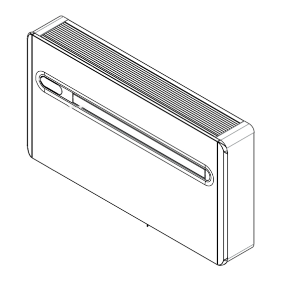
Page 7: Unit Parts
GENERAL Unit parts Air outlet flaps Air filters Touch-screen display Outdoor air outlet fan Outdoor air heat exchanger Front panel Compressor Outdoor air suction Indoor air heat exchanger Outdoor air outlet Air suction grid Electronic board... -
Page 8: Installation
INSTALLATION INSTALLATION Installation mode Before installing the conditioner, it is essential to calculate Cover large windows exposed to sunlight with curtains the summer thermal loads (and winter ones for the models or with external maskings (blinds, porches, reflecting with a heat pump) of the room. The more calculations are films, etc.). exact, the better the product will work. Please refer to current The room must remain closed for as long as possible. regulations to carry out calculations. For big installations Avoid using halogen lamps or other high energy please call a study specialised in thermotechnics. Try to consumption appliances such as small ovens, steam reduce the thermal refrigeration load of the room following irons, cooking plates etc. instructions below: Choosing the position of the unit For a better performance of the appliance and to avoid Check that there are no structures or systems (beams, malfunctions or dangerous situations, the location of the... -
Page 9: Assembling The Unit
INSTALLATION Assembling the unit The maximum length of the holes is of 1 m and there The holes must be drilled slightly downwards to avoid must be no bends. Use the supplied grids or grids water from entering. with the same characteristics. The majority of the removed material is expelled outwards, For the unit to work, two holes must be placed as indicated so please be careful that it doesn't hit people or objects. In on the template; order to avoid breaking the outer plaster, be careful while drilling the final part of the hole and ease the pressure on The holes on the wall must be drilled using suitable the core drill. equipment that facilitates your work and that does not Drill the 6 holes for the bracket as indicated on the cause damage or excessive inconvenience to Your client. - Page 10 INSTALLATION Condensation drain predisposition For heat pump appliances, a condensation drain pipe The exact position in which to place the pipe mouth is (Ø10 mm, internal, not supplied) must connect the unit to indicated on the template. the pipe on the top part of the appliance. A solenoid valve will start the flow of the condensation Check that the expelled water does not cause any from the internal collection tray when the maximum level damage or problems to people or objects. During has been reached. For cooling only appliances, said pipe winter, this water may create sheets of ice outside.
-
Page 11: Assembling Air Ducts And External Shutters
INSTALLATION Assembling air ducts and external shutters Once the holes have been made, place the supplied use a bolt cutter to remove any excess chain. plastic sheets inside them. anchor the hook of the chain to wall B. Roll up the sheet and insert it in the hole, checking that the A junction line is aiming upwards. Use only the supplied grids or grids with the same Use a cutter to remove any excess pipe. characteristics. To place the external grids, proceed as follows: connect the chains to the ends of the springs; fold the external shutters; insert your arm in the hole to push the shutter outside while holding the ends of the chains with the other hand to prevent them from falling down;... -
Page 12: Electrical Connection
INSTALLATION Electrical connection The appliance is equipped with a power cord and plug This operation must be performed only by the installer (Y-type connection, the cord can only be replaced by the or by authorised personnel in compliance with current manufacturer, the assistance centre or a qualified installer). national regulations If using a socket near the appliance, insert the plug. It is essential to disconnect the main switch before making Before connecting the conditioner check that: any connection or maintenance operation in order to avoid The power supply voltage and frequency values any risk of electrocution. comply with the data plate of the appliance. To carry out direct connections and substitute the power The power supply line is provided with a suitable earth cord using the cable in the wall, proceed as follows: connection and that it is dimensioned for the maximum Space the appliance from the wall using a wooden absorption of the conditioner (minimum cable section wedge or a similar object. -
Page 13: High/Low Installation Configuration
INSTALLATION High/low installation configuration The unit can be installed either in the lower part (near the in cooling mode, which increases the air flow in the room floor) or in the upper part (near the ceiling) of the wall. In (coanda effect). order to optimise air distribution and comfort, the direction of the air flow can be modified by adjusting the position of This operation must be performed while the appliance the air flap. is switched off and disconnected. The appliance is supplied ready to be installed in the lower part of the wall, so air is dispensed upwards. The same configuration can also be used in the upper part of the wall Adjust the air outlet flap configuration from the lower wall position to the upper wall position. Open the air outlet flap gently High installation Remove the flap opening block insert located internally on the right of the air outlet mouth and place it in the Low installation (factory settings) lower hole. Block insert After adjusting the air outlet flap position, it is necessary to If no other operations are performed in the following 2 set up the electronic control of the appliance:... -
Page 14: Touch-Screen Display Key Lock
INSTALLATION Touch-screen display key lock The stand-by symbol flashes at 1 second intervals. The key lock is activated by keeping the Timer symbol To deactivate the lock, keep the Timer symbol pressed for on the touch-screen display pressed for t h r e e three seconds once again. seconds. Any key on the remote control deactivates the lock! Any action is prevented by the user. 2.10 Operations tests and anomaly diagnosis The conditioner can perform a short self-diagnosis cycle After 5 cycles, or when any key is pressed either in the to check the temperatures detected by the 4 probes and display or on the remote, the self-diagnosis mode will the status of the 3 inlets. -
Page 15: Periodic Maintenance
MAINTENANCE MAINTENANCE Periodic Maintenance The air conditioner you have bought has been designed concern the following cleaning operations. to keep maintenance operations to a minimum, which only External cleaning Before any cleaning and maintenance operation, Do not use abrasive sponges or abrasive or corrosive disconnect the unit from the mains by switching off detergents to avoid damaging varnished surfaces. the main switch. When necessary, clean the external surfaces with a soft Wait until the parts have cooled down to avoid getting damp cloth. burned. Cleaning filtering seats The air conditioner you have bought has been designed To extract the filters: to keep maintenance operations to a minimum, which only open the grid and remove it; concern the following cleaning operations: extract the filters by lifting them; Clean the air filter after a period of continuous use and remove the dust from the filter with a vacuum cleaner in accordance with the concentration of impurities in... -
Page 16: Troubleshooting
MAINTENANCE Troubleshooting In case of malfunctioning, please refer to the following table. If, please contact the authorised technical assistance. after performing the suggested checks, the problem is not solved, Anomaly Possible cause Solution Check the voltage (by turning the light on, for example). Check that the exclusive magneto-thermic switch that protects The appliance No power supply the appliance hasn't intervened (if it has, reset it). If the problem doesn't switch repeats immediately, please call the Service Centre and avoid trying to make the appliance work. Check that the appliance turns on using the touch-screen display Batteries ran out and substitute the batteries. -
Page 17: Technical Data
MAINTENANCE Technical data Please read the data plates to obtain the technical data listed below. Power supply voltage Maximum absorbed power Maximum absorbed current Amount of refrigerant gas Casing protection level Max. working pressure U.M. “2.0” 8 HP "2.0" 10 HP Technical data Cooling power (1) 1.65 2.30 Heating power (2) 1.70 2.25 Power absorbed when cooling (1) Power absorbed when heating (2) Annual energy consumption for cooling (1) Dehumidification capacity Power supply voltage... - Page 18 NOTES...
- Page 19 NOTES...
- Page 20 INNOVA s.r. l . INNOVA s.r. l . Fraz . St rada, 16 - 38085 PIEVE DI BONO (TN) - ITALY Fraz . Strada, 16 - 38085 PIEVE DI BONO (TN) - ITALY tel. +39.0465.670104 fax +39.0465.674965 tel. +39.0465.670104 fax +39.0465.674965 info@innovaenergie.com...
Need help?
Do you have a question about the 2.0 and is the answer not in the manual?
Questions and answers