Table of Contents
Advertisement
Advertisement
Table of Contents

Related Manuals for Innova Filomuro SLW Series


Summary of Contents for Innova Filomuro SLW Series
- Page 1 Installation and user manual...
- Page 2 By following the suggestions contained in this manual, the product that you have purchased will operate without problems giving you optimum room temperatures with minimum energy costs. INNOVA S.r.l. Conformity This unit complies with the European directives: •...
-
Page 3: Table Of Contents
General � � � � � � � � � � � � � � � � � � � � � � � � � � � � � � � � � � � � � � � � � � � � � � � � � � � � � � � � � � � � � � � � � � � � � � � � � � � 4 1.1 General warnings . -
Page 4: General
GENERAL GENERAL 1�1 General warnings After unpacking, make sure that all the components are – close the water taps present. If not, contact your vendor who sold the device – if there is a danger of frost, make sure that you have added to you. -
Page 5: Product Line
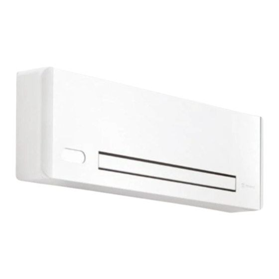
GENERAL 1�3 Product line Filomuro fancoils range are designed for wall installation. • with touchpad and remote control The device are are made in three different performance lev- • for connection with remote control at modulating speed els and size, all for two-pipe configuration. Filomuro fancoils range are available into three configura- •... -
Page 6: Dimensions And Weight During Transportation
GENERAL 1�6 Dimensions and weight during transportation Filomuro Filomuro Filomuro Models m.u. Dimensions and weight during transportation Total length 1020 1220 1302 Total height Total depth Weight 15,00 17,00 20,00... -
Page 7: Installation
INSTALLATION INSTALLATION 2�1 Unit placement The siting of the device must be established by the system • in environments subject to high frequencies designer or other qualified professional and must take into Make sure that: account both technical requirements and any local laws in force. -
Page 8: Device Preparation
INSTALLATION 2�4 Device preparation Before proceeding with the installation, it is necessary to remove some elements from the appliance. Remove the filter Filter Filter Extraction direction – lift the filter slightly – remove the filter – rotate until the complete exit from the housing Removal of the aesthetic front panel side panels fixing screws... -
Page 9: Predisposition To Installation
INSTALLATION Remove the side panels Side panels – unscrew the fixing screw Upper screws – remove the side panels Left side screws 2�5 Predisposition to installation built-in cistern To install the appliance, use a recessed box to contain the connecting water pipelines connections. - Page 10 INSTALLATION dowels bracket – assemble the unit – check correct attachment to the bracket – insert the expansion plugs – position the support brackets – partially screw the screws Do not fully fix the screws so that you can adjust the posi- tion of the appliance.
-
Page 11: Hydraulic Connections
INSTALLATION 2�7 Hydraulic connections The engineer is responsible for choosing the right water lines Keep in mind that undersized pipelines lead to poor sys- and their size, in accordance with good installation practices tem operation. and the applicable law. Position and dimensions Models m.u. - Page 12 INSTALLATION Connection to the system To make the connections: The hydraulic lines and fittings must be thermally insulat- – hydraulic lines positioning Avoid partial insulation of the pipes. – use the "wrench against wrench" method Avoid over-tightening the pipes to avoid damage to the –...
- Page 13 INSTALLATION Connection with 2-way valve and thermoelectric actuator (V20687) In case of choice for the 2-way valve and thermoelectric ac- • connect the pipe with the delivery line at the top tuator: Filomuro thermoelectric motor fitting for water inlet pipe water outlet pipe fitting electrical cable entry hole Connection with 3-way diverting valve unit with thermoelectric actuator (V30688)
-
Page 14: Condensate Drain
INSTALLATION 2�8 Condensate drain The unit is complete of a drain pan that collects the con- densate fluid that is produced during cooling operation and must be conveyed to a suitable place for unloading. 1� drain connection, Ø 14 mm Connection to the condensate drain drain connection Filomuro... -
Page 15: Filling The System
INSTALLATION 2�9 Filling the system To fill the system: Regularly check the system's pressure. – open the vent valves Coil vent – open all the system's shut-off devices – slowly open the water tap When water begins to leak out of the breather valves: –... - Page 16 INSTALLATION terminal block for connection – bring the power cord to the terminal block – making the connections – refer to the information in the wiring diagram of the unit you are installing You can use a cable embedded in the wall in the position traced with the installation template to make the electrical connection (recommended connection for devices installed in the upper part of the wall).
-
Page 17: Diagrams And Configurations Electrical Controls
INSTALLATION 2�11 Diagrams and configurations electrical controls Touchpad and remote control (code suffix-0Q00) Printed circuit board EB0689 The PCB is included in the supply. Water temperature probe Fan motor DC Inverter Hot water solenoid valve (230 V/50 Hz 1 A power output) L-N 230 V/50 Hz electrical power supply connection Protective conductor Presence sensor input (if closed, the fancoil goes into stand-by) - Page 18 INSTALLATION Remote control EDA649 - EDB649 / EWG649 - EWW649 (code suffix-0P00) Printed circuit board ER0690 The PCB is included in the supply. -AB+ Serial connection for wall-mounted remote control (respect the AB polarization) Hot water temperature probe 10 kΩ Fan motor DC Inverter Water solenoid valve (230 V/50 Hz 1 A power output) L-N 230 V/50 Hz electrical power supply connection...
- Page 19 INSTALLATION Wall mounted remote control EDA649 - EDB647 / EWG649 - EWW649 The control panel is to be ordered separately. – if the wire is rigid, you can insert it easily whereas Terminal blocks – if it is flexible, it is advisable to use long nose pliers –...
- Page 20 INSTALLATION Remote control with fixed speed (code suffix-0T00) Printed circuit board BB0698 The PCB is included in the supply. N-L 230 V/50 Hz electrical power supply Solenoid valve permission input Maximum fan speed 1.400 rpm Medium fan speed 1.100 rpm Minimum fan speed 680 rpm Super-silent speed 400 rpm Heating, cooling selection input...
- Page 21 INSTALLATION Connection with 3 speed thermostats The CV input is the ON/OFF of the board: • V4 - supersilent speed (equal to 400 rpm) Connect the 3 speeds of the thermostat to three of the four • in case of opened input the PCB is placed in stand-by available inputs based on the characteristics and use of the •...
- Page 22 INSTALLATION Remote control with modulating speed (code suffix-0V00) Printed circuit board BB0699 The PCB is included in the supply. L-N 230 V/50 Hz electrical power supply 10V Device pilot input 0÷10 V. Input impedance 25 kΩ Water solenoid valve (230 V/50 Hz 1 A power output) Fan motor DC Inverter N276659C...
- Page 23 INSTALLATION Connection with 0-10 V thermostats The 10 V input activates solenoid valve Y1 and adjusts the The solenoid valve Y1: number of rotations of the fan. The speed range provides a • is enabled by voltage values > 1 V DC linear adjustment from the minimum value (400 rmp) to the maximum value (1400 rmp) for voltage values ≥...
-
Page 24: Touchpad And Remote Control
TOUCHPAD AND REMOTE CONTROL TOUCHPAD AND REMOTE CONTROL 3�1 Interface Description The solution with touch pad and remote control is recom- • Do not expose the remote control to direct sunlight. mended for the prevalent use in cooling. •... -
Page 25: Main Functions
TOUCHPAD AND REMOTE CONTROL Remote control Keys and functions related. Up key Down key On/off key Not used Key to enable cooling only mode Not used Key to enable ventilation only mode Key to enable heating only mode Night comfort key Airflow direction control key Fan speed control key Key to set the Timer function... - Page 26 TOUCHPAD AND REMOTE CONTROL Cooling only mode To select the Cooling operation press the key for about 2 seconds – The symbol on indicate the Cooling function enable When this operating mode is enabled, the device dehumid- temperature, the fancoil starts and starts supplying cold air, ifies and cools the room.
- Page 27 TOUCHPAD AND REMOTE CONTROL Set the direction of the air flow To control the air flow direction press the key for about 2 seconds – The symbol lit on indicates the constant oscillation of the air flow deflector To lock the airflow direction again press again the –...
-
Page 28: Warnings
TOUCHPAD AND REMOTE CONTROL 3�3 Warnings Visualization of alarms on display In the event of a malfunction, the display shows an alarm Room temperature probe (RT) failure code. It is possible to normally activate the Cooling, Dehu- midification and Heating modes. In the event of an alarm, the device still maintains active functions. -
Page 29: Wall Mounted Remote Control Eda649 - Edb647 / Ewg649 - Eww649
TOUCHPAD AND REMOTE CONTROL WALL MOUNTED REMOTE CONTROL EDA649 - EDB647 / EWG649 - EWW649 4�1 Installation Description The wall-mounted control panel is a thermostat with possi- The temperature probe can be remoted in one of the fan- bility of control on several device equipped with electronic coils connected to it. -
Page 30: Electric Connections
TOUCHPAD AND REMOTE CONTROL For the remote control wall mounting: Base of the control Holes for the wall mounting – drill holes in the wall Screws – pull the electric wires through the hole provided Hole for the passage of the electrical connections –... - Page 31 TOUCHPAD AND REMOTE CONTROL Terminal block position Terminal block The spring terminals allow the connection of rigid or flexible cables with sections from 0.2 to 1 mm². For cables provided with lugs with plastic collar the maximum section is reduced to 0,75 mm².
-
Page 32: Interface
TOUCHPAD AND REMOTE CONTROL 4�3 Interface Description The wall-mounted control panel EDA649-EDB649 / EWG649- The control can control up to a maximum of 30 units. EWW649 is a thermostat with possibility of control on several The room temperature probe ensures an antifreeze safety device equipped with electronic control for remotization. -
Page 33: Main Functions
TOUCHPAD AND REMOTE CONTROL To activate the device press the – he symbol lights up 4�4 Main functions Operating mode set-up to switch the operating mode press the key for about 2 seconds – The symbol on indicates the Heating function enable The symbol on indicate the Cooling function enable In heating function the symbols is alight with setpoint... -
Page 34: Warnings
TOUCHPAD AND REMOTE CONTROL Maximum ventilation speed To select the operation at the maximum ventilation speed press the key for about 2 seconds – The symbol on indicates the maximum speed function enable Maximum power output is immediately obtained both in After reaching the desired room temperature, select a dif- heating and cooling. -
Page 35: Wall-Mounted Control B3V151 - B3V152
TOUCHPAD AND REMOTE CONTROL WALL-MOUNTED CONTROL B3V151 - B3V152 5�1 Electric connections Connection diagram B3V151 1� 2� Wall control H4 H2 S1 DATA I/O N276660C B3V152 1� 2� Built-in wall control H4 H2 S1 DATA I/O N276660C... -
Page 36: Maintenance
MAINTENANCE MAINTENANCE 6�1 Routine maintenance Routine maintenance is essential to keep the device always Warnings: efficient, safe and reliable over time. • Do not lean or sit on the fancoil to avoid damaging the It can be done: appliance. - Page 37 MAINTENANCE Filter extraction Filter Filter Extraction direction To extract the filter: – remove the filter – lift it slightly – rotate until the complete exit from the housing Cleaning Vacuum cleaner Running water Long nozzle Filter Filter – wash the filter with running water To clean the filters: –...
-
Page 38: Suggestions For Energy Saving
MAINTENANCE 6�2 Suggestions for energy saving For a correct operation of the device and a great energy sav- ing: • keep the filters clean • keep the doors and windows of the locations fitted with air conditioning systems closed as much as possible •... -
Page 39: Troubleshooting
TROUBLESHOOTING TROUBLESHOOTING 7�1 Preliminary warnings Should you encounter any of the anomalies below: – disconnect the device from power supply immediately • the ventilation does not start even if the water circuit is – close the water taps filled with hot or cold water –... - Page 40 TROUBLESHOOTING NOTE...
- Page 41 TROUBLESHOOTING NOTE...
- Page 42 TROUBLESHOOTING NOTE...
- Page 43 TROUBLESHOOTING NOTE...
- Page 44 INNOVA S.r.l. Via I Maggio 8 - 38089 Storo ( TN) - ITALY tel. +39.0465.670104 – fax +39.0465.674965 info@innovaenergie.com N273110A - Rev. 06...
Need help?
Do you have a question about the Filomuro SLW Series and is the answer not in the manual?
Questions and answers