
Related Manuals for Innova 2.0 10 HP


Summary of Contents for Innova 2.0 10 HP
- Page 1 Installation manual something new in the air something new in the air 8 - 10 - 12...
- Page 2 We are sure you will be happy with it because it represents the state of the art in the technology of home air conditioning. By following the suggestions contained in this manual, the product you have purchased will operate without problems, giving you optimum room temperatures with minimum energy costs. Innova S.r.l Compliance This unit complies with European directives: •...
-
Page 3: Table Of Contents
General General warnings ............. . . Fundamental safety rules . -
Page 4: General
If it gets damaged or destined solely for this purpose compatibly with their lost, please request another copy to the local INNOVA performance characteristics. Technical Assistance Service. The manufacturer refuses any contractual or extra-... -
Page 5: Description
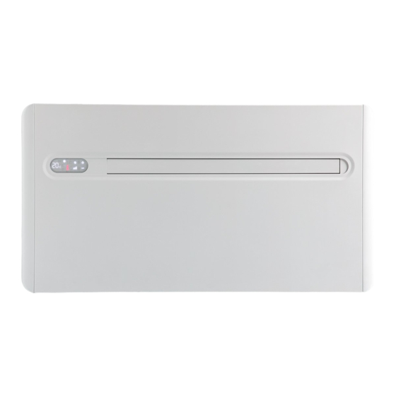
GENERAL Description "2.0" is the new solution by INNOVA, a significant step Energy consumption is extremely reduced thanks to towards reducing the aesthetic impact of air conditioners. absorption values falling down under 300 W in the case Being only 16 centimetres deep, "2.0" is the thinnest and of partial load. -
Page 6: Handling
Handling The unit is packed singularly in a cardboard box. Boxes During transportation, the appliance must be kept in can either be carried singularly by hand by two operators vertical position. or loaded on a cart, for a maximum of three units. Handling must be performed by qualified personnel, with specific tools and with equipment suitable for the weight of the appliance. -
Page 7: Unit Parts
GENERAL Unit parts Air outlet flaps Air filters Touch-screen display Condensation drain pipe Front panel Room air probe Outdoor air suction Power supply terminal board Aesthetic side panel Outdoor air outlet Anti-lifting bracket Internal air intake grille... -
Page 8: Installation
INSTALLATION Installation mode Before installing the conditioner, it is essential to calculate Cover large windows exposed to sunlight with curtains the summer thermal loads (and winter ones for the models or with external maskings (blinds, porches, reflecting with a heat pump) of the room. The more calculations are films, etc.). -
Page 9: Assembling The Unit
INSTALLATION Assembling the unit For the unit to work, two holes Ø162 must be placed as The majority of the removed material is expelled outwards, indicated on the template; so please be careful that it doesn't hit people or objects. In order to avoid breaking the outer plaster, be careful while The maximum length of the holes is of 1 m and there drilling the final part of the hole and ease the pressure on... -
Page 10: Condensation Drain Predisposition
Condensation drain predisposition For heat pump appliances, a condensation drain pipe The exact position in which to place the pipe mouth is (Ø10 mm, internal, not supplied) must connect the unit to indicated on the template. the pipe on the top part of the appliance. A solenoid valve will start the flow of the condensation Check that the expelled water does not cause any from the internal collection tray when the maximum level... -
Page 11: Mounting The Appliance On The Bracket
INSTALLATION Once installation of the grilles is complete check their the external air flow is activated, to allow the cooling and opening (towards the inside of the duct for the air inlet heating functions to be operated. The conditioner must be grid "IN"... -
Page 12: Electrical Connection
Electrical connection The appliance is equipped with a power cord and plug It is possible to carry out the electrical connection using (Y-type connection, the cord can only be replaced by the a cable inside of the wall as indicated in the installation manufacturer, the assistance centre or a qualified installer). -
Page 13: High/Low Installation Configuration
INSTALLATION High/low installation configuration The unit can be installed either in the lower part (near the in cooling mode, which increases the air flow in the room floor) or in the upper part (near the ceiling) of the wall. In (coanda effect). -
Page 14: Setting Cool Only Or Heat Only Modes
Setting cool only or heat only modes It is possible to deactivate the heating or the cooling mode. modes following a simple procedure. Press the A key again for Ho (heating only) mode. Keep the A key on the touch-screen display pressed for Wait for 3 seconds without touching anything to memorise 5 seconds until HC (heating and cooling) appears on the the setting. - Page 15 MAINTENANCE Use of the appliance removes ice that may have formed on the external No structural obstacles or objects (furniture, curtains, battery. In this condition the machine is active but does plants, leafage, shutters, etc.) must ever obstruct the not send hot air to the room. This stage may last from 3 normal air flow both from the internal and from the to 10 minutes.
-
Page 16: Periodic Maintenance
MAINTENANCE Periodic Maintenance The air conditioner you have bought has been designed concern the following cleaning operations. to keep maintenance operations to a minimum, which only External cleaning Before any cleaning and maintenance operation, Do not use abrasive sponges or abrasive or corrosive disconnect the unit from the mains by switching off detergents to avoid damaging varnished surfaces. -
Page 17: Troubleshooting
MAINTENANCE Troubleshooting In case of malfunctioning, please refer to the following table. If, please contact the authorised technical assistance. after performing the suggested checks, the problem is not solved, Anomaly Possible cause Solution Check the voltage (by turning the light on, for example). Check that the exclusive magneto-thermic switch that protects The appliance No power supply... -
Page 18: Technical Data
Technical data Please read the data plates to obtain the technical data listed below. Power supply voltage Maximum absorbed power Maximum absorbed current Amount of refrigerant gas Casing protection level Max. working pressure U.M. “2.0” 8 HP "2.0" 10 HP "2.0"... - Page 19 NOTES...
- Page 20 INNOVA s.r. l . INNOVA s.r. l . Fraz . St rada, 16 - 38085 PIEVE DI BONO (TN) - ITALY Fraz . Strada, 16 - 38085 PIEVE DI BONO (TN) - ITALY tel. +39.0465.670104 fax +39.0465.674965 tel.
Need help?
Do you have a question about the 2.0 10 HP and is the answer not in the manual?
Questions and answers