
Related Manuals for Lindy P16-IP


Summary of Contents for Lindy P16-IP
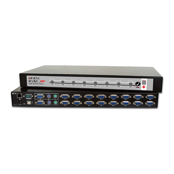
- Page 1 P16-IP KVM Switch User Manual For Commercial Use Only Tested to comply with FCC Standards © LINDY ELECTRONICS LIMITED & LINDY-ELEKTRONIK GMBH - FIRST EDITION (Nov 2006) LINDY No. 32532 www.lindy.com English...
-
Page 2: About This Manual
About this manual This manual is divided into four sections. The first section is an introduction to the P16-IP; the second section deals with installing and connecting the switch; the third section describes the basic operation of the KVM switch from the locally connected console; the fourth section... -
Page 3: Table Of Contents
Contents SECTION 1 ... 3 About the P16-IP ... 4 Product Features ... 5 Package Contents... 6 Optional Cables and Accessories (not included) ... 6 SECTION 2 ... 7 Product Information & Connections ... 8 Rackmount Installation ... 9 Connecting an External Power Switch option... 9 Cascading / Daisy Chaining of multiple KVM Switches ... -
Page 4: Section 1
Section 1 Introducing the P16-IP... -
Page 5: About The P16-Ip
USB to PS/2 adapter cable (LINDY No. 42866.) The switch can be easily daisy chained with other LINDY P-series KVM switches (P4, P8 or P16, it cannot be used with PXT switches) to support up to 128 computer connections in total, all controlled from a single local console or via IP access. -
Page 6: Product Features
16 port KVM switch in a 1U, 19” rackmount size design Local console operation and KVM over IP control Support for LINDY mice and for all mice up to 5 buttons and 2 wheels with fully Microsoft compatible drivers. Some advanced features and proprietary functions of wireless/RF mice and keyboards with non-standard Microsoft®... -
Page 7: Package Contents
Standard 3-in-1 KVM cables can be used to daisy chain the switch. P16-IP KVM Cable (15 Way HD Male to 15 Way HD Male + 2 x PS/2 Male) P16-IP KVM Cable LINDY No. 32506 LINDY No. -
Page 8: Hardware Installation
Section 2 Hardware Installation... -
Page 9: Product Information & Connection Guide
Daisy Chain Ports These ports allow a slave P-Series KVM switch to be connected to the P16-IP using standard 3- in-1 PS/2 & VGA KVM cable. USB Port Use the supplied cable to connect to a computer for remote mass storage support. -
Page 10: Rackmount Installation
2.3 Connecting an External Power Switch option At the time of writing (November 2006) the P16-IP supports the following external power switch options. Please refer to the individual manufacturers manuals for advice on connecting to the P16-IP. -
Page 11: Cascading / Daisy Chaining Of Multiple Kvm Switches
Section 2 2.4 Cascading / Daisy Chaining of multiple KVM Switches The P16-IP can be cascaded with LINDY P-Series CPU switches only. It should not be used with LINDY PXT-Series CPU Switches. For all cascaded installations, the P16-IP should always be used as the MASTER switch. -
Page 12: Kvm Switch Operation
Section 3 KVM Switch Operation... -
Page 13: Password Security
Password Security When you power on the P16-IP it will ask you for a password. The default password is eight zeros –“00000000”. Please key in eight zeros in the password field. - Page 14 “↵” and the required port button simultaneously. For cascaded KVM Switches you can ONLY use the port selection push buttons on the MASTER P16-IP Switch to switch the SLAVES (you can also switch via OSD or keyboard hotkey).
-
Page 15: Keyboard Hotkey Selection
Within 2 seconds Scroll Scroll Lock Lock KVM Switch/Bank Selection: The P16-IP supports cascading of up to 8 KVM Switches (Banks). Therefore, when using direct hotkey port selection you must include the key sequence for the KVM Switch/Bank: Scroll Scroll Lock Lock... - Page 16 Section 3 Auto Scan mode: Scroll Scroll Lock Lock Beeper Function (Enables and Disables beep during Auto Scan): Scroll Scroll Lock Lock Auto Scan (Press any key to exit Auto Scan Mode) Beeper KVM Switch Operation...
-
Page 17: On Screen Display Menu (Osd) Port Selection
OSD settings menu. The time selected can be between 5 and 99 seconds The OSD menu can be invoked even when the P16-IP is currently switched to a port with no connected or a non-powered on PC. In this case the resolution of OSD menu is fixed to a 1024 X 768 virtual frame. - Page 18 TAB : NEXT / : SELECT PORT PgDn/PgUp: BANK SELECT f. Use the “PgUp” or “PgDn” key to switch to another daisy chained KVM Switch / Bank. This function only works when another KVM Switch/Bank is connected. SYSTEM 01 OSD : SEC.
- Page 19 ESC : QUIT NEW PASSWORD COMPLETE ESC : QUIT When you have switched to a certain port on the KVM Switch the keyboard and mouse commands are directed to the attached computer and its monitor signal is displayed on the screen.
-
Page 20: Section 4
Section 4 IP Access Configuration & Operation... -
Page 21: Configuration
Initial Configuration via a DHCP Server By default, the P16-IP will try to contact a DHCP server in the subnet to which it is physically connected. If a DHCP server is found, it will provide a valid IP address, gateway address and net mask. -
Page 22: P16-Ip Setup Tool
4.2 P16-IP Setup Tool MAC Address Detection Connect the P16-IP to your computer either via a local network, or via USB. If you use a USB connection Windows will detect the P16-IP as a ‘Removable Disk’ and an appropriate drive letter will be assigned. -
Page 23: Ip Auto Configuration
IP Auto Configuration With this option, you can specify whether the P16-IP should obtain its network settings from a DHCP or BOOTP server. From the drop down list select either DHCP or BOOTP. If you select NONE, the IP auto configuration is disabled and you should manually input the following... -
Page 24: Keyboard, Mouse And Video Configuration
P16-IP Keyboard Settings The P16-IP settings for the host' s keyboard type have to be correct in order to make the remote keyboard work properly. The settings can be checked using the P16-IP front-end (see page 33) -
Page 25: Single And Double Mouse Mode
The information above applies to Double Mouse Mode, where both remote and local mouse pointers are visible and need to be synchronized. The P16-IP also features another mode - Single Mouse Mode, where only the remote mouse pointer is visible. Activate this mode in the open Remote Console and click into the window area. -
Page 26: Recommended Mouse Settings
The P16-IP switch recognizes a limited number of common video modes. When running X11 on the host system, please do not use any custom mode lines with special video modes. If you do, the P16-IP switch may not be able to detect them. We recommend using any of the standard VESA video modes instead. -
Page 27: Usage
The interfaces are accessed using the TCP/IP protocol family. The following interfaces are supported: Telnet A standard Telnet client can be used to access an arbitrary device connected to the P16-IP’s serial port via a terminal. HTTP/HTTPS Full access is provided by the embedded web server. The P16-IP switch environment can be entirely managed using a standard web browser. -
Page 28: Logging In
Please make sure you change the super user password immediately after you have installed and accessed your P16-IP for the first time. Not changing the password for the super user is a severe security risk and could result in unauthorized access to the switch and to the host system(s) to which it is connected. -
Page 29: Navigation
Section 4 4.6 Navigation Once logged into the P16-IP successfully, the main page appears. This page consists of three parts; each of them contains specific information. The buttons in the upper area allow you to navigate within the front end. The lower left area contains a navigation bar and allows you to switch between the different sections of the P16-IP. -
Page 30: Remote Console Main Window
P16-IP. The Remote Console will behave in exactly the same way as if you were using the local console. You can use the P16-IP keyboard hotkeys to switch between computers, activate the OSD etc., as well as control the currently selected computer. -
Page 31: Remote Console Control Bar
Auto Adjust button If the video display is poor quality or distorted in some way, click this button and wait a few seconds while the P16-IP tries to adjust itself for the best possible video quality. Sync mouse Activates the mouse synchronization process. Choose this option in order to synchronize the local AND remote mouse cursors. - Page 32 Video Settings in the KVM section in the front end menu: The Noise Filter option defines how the P16-IP reacts to small changes in the video input signal. A large filter setting needs less network traffic and leads to a faster video display, but small changes in some display regions may not be recognized immediately.
- Page 33 Section 4 IP Access Configuration & Operation Video Settings through the remote console: Brightness Controls the brightness of the picture Contrast Controls the contrast of the picture Clock Defines the horizontal frequency for a video line and depends on the video mode. Different video card types may require different values here.
- Page 34 Section 4 IP Access Configuration & Operation Undo Changes Restore last settings Soft Keyboard Opens up the sub-menu for the Soft-Keyboard: Show Pops up the Soft-Keyboard. The Soft-Keyboard is necessary in case your host system runs a completely different language and country mapping than your administration machine. Mapping Used for choosing the language and country mapping of the Soft-Keyboard.
-
Page 35: Remote Console Status Line
Section 4 IP Access Configuration & Operation Remote Console Status Line Status line Shows both console and the connection state. The size of the remote screen is displayed. The example below was taken from a Remote Console with a resolution of 1024 x 768 pixels. The value in brackets describes the connection to the Remote Console. -
Page 36: Menu Options
Section 4 IP Access Configuration & Operation 4.7 Menu Options 4.7.1 Remote Control KVM Console To open the KVM console, click either the menu entry on the left or on the console picture on the right. To refresh the picture, click on the Refresh button. For the Remote Power settings see Section 2.3 on page 9. -
Page 37: Telnet Console
P16-IP host is using a text mode screen resolution. Connecting to the P16-IP is done as usual and as required by the Telnet client, for instance in a UNIX shell: telnet 192.168.1.22... - Page 38 Section 4 IP Access Configuration & Operation The following list shows the command mode syntax and usage. Help Displays the list of possible commands Clears the screen Quit Exits the current session and disconnects from the client Version Displays the release information Terminal Starts the terminal pass-through mode for the serial port.
-
Page 39: Virtual Media
IP Access Configuration & Operation 4.7.2 Virtual Media One of the computers connected to the P16-IP can also be set up for remote mass storage via a USB connection. Files can be uploaded to the switch, which the host computer ‘sees’ as virtual drives. - Page 40 A virtual floppy drive will be installed on the host system and the image will be downloaded to the virtual floppy drive from the P16-IP. You can access the virtual floppy drive in the same way you would a regular drive.
-
Page 41: Create A Cd-Rom/Iso Image
Follow the procedure below to create a CD-ROM image which can be accessed by the host system via the P16-IP. The image file must be an ISO file format! First, on your client PC you must create an image of your CD which can be accessed by the host system. - Page 42 Click Apply complete. 4. Next you need to mount the image via a Windows Share. In the P16-IP menu on the left hand side of the browser select Virtual Media and from the sub menu select CD- ROM Image. 5. Input the following parameters: Enter the IP address of your Console PC here (e.g.
- Page 43 Section 4 7. You will see the dialog below detailing the active image: 8. Click Reactivate. Access the console window and you will see that another CD drive has been installed on the host computer. This is the virtual drive you have just set up. You can access the uploaded CD image as though it were a regular CD.
-
Page 44: Drive Redirection
Section 4 IP Access Configuration & Operation Drive Redirection The Drive Redirection feature allows the host system to access the CD-Rom drives, hard drives, floppy drives etc. on your client PC. To use this feature you need the Drive Redirection Tool which is part of the KVM Vision Viewer application included on the supplied CD. - Page 45 (default is pass). 4. Continue with the Wizard until the device is correctly configured. Once the configuration is complete, select Redirect Local Drive from the Device menu: IP Access Configuration & Operation The P16-IP will be detected as an...
- Page 46 Section 4 1. Choose the drive you wish to redirect from the drop-down list. Enter your user name and password and click OK. Warning: Please be aware that if Allow Write Support is selected, data on the shared media may be lost! 2.
-
Page 47: User Management
Section 4 IP Access Configuration & Operation 4.7.3 User Management Change Password To change your password, enter the new password in the upper entry field. Retype the password in the lower field. Click Apply to submit your changes. -
Page 48: Users And Groups
IP Access Configuration & Operation Users And Groups The P16-IP comes with 2 pre-configured user accounts that have fixed permissions. The super account has all possible rights to configure the device and to use all functions. The user account has only the permission to open and use the Remote Console. The default password for both accounts is pass. -
Page 49: Kvm Settings
Section 4 IP Access Configuration & Operation 4.7.4 KVM Settings User Console The following settings are user specific. This means the super user can customize these settings for individual users separately. Changing the settings for one user does not affect the settings for the other users. - Page 50 Allows adjustment of both compression rate and colour depth individually. Depending on the selected compression rate the data stream between the P16-IP and the Remote Console will be compressed in order to save bandwidth. Since high compression rates are very time consuming, they should not be used when several users are accessing the P16-IP simultaneously.
- Page 51 Miscellaneous Remote Console Settings Start in Monitor Mode Sets the initial value for the monitor mode. By default the monitor mode is off. In case you switch it on, the Remote Console window will be started in a read only mode.
- Page 52 Section 4 Keyboard/Mouse Host Interface Enables the interface the mouse is connected to. You can choose between Auto for automatic detection, USB for a USB mouse, or PS/2 for a PS/2 mouse. Note: To use the USB and/or PS/2 interface you need the correct cabling between the managed host and the managing device.
- Page 53 Miscellaneous Video Settings Noise filter This option defines how the P16-IP reacts to small changes in the video input signal. A large filter setting needs less network traffic and leads to a faster video display, but small changes in some display regions may not be recognized immediately. A small filter displays all changes instantly but may lead to a constant amount of network traffic even if the display content is not IP Access Configuration &...
-
Page 54: Device Settings
Note: The initial IP configuration is usually done directly at the host system using the special procedure described on Page 20. Changing the network settings of the P16-IP might result in losing connection to it. In case you change the settings remotely make sure that all the values are correct and you still have an option to access the P16-IP. - Page 55 IP Access Configuration & Operation IP auto configuration With this option you can control if the P16-IP should obtain its network settings from a DHCP or BOOTP server. For DHCP, select dhcp, and for BOOTP select bootp. If you choose none then IP auto configuration is disabled.
-
Page 56: Dynamic Dns
The administrator has to register a P16-IP that is supposed to take part in the service with the Dynamic DNS Server and assign a certain hostname to it. He will get a nickname and a password in return. - Page 57 Hostname This is the hostname of the P16-IP that is provided by the Dynamic DNS Server. (Use the whole name including the domain, e.g. testserver.dyndns.org not just the actual hostname).
- Page 58 If this option is enabled, access to the web front-end is only possible using an HTTPS connection. The P16-IP will not listen on the HTTP port for incoming connections. If you want to create your own SSL certificate that is used to identify the P16-IP please refer to the section called Certificate on page 58.
- Page 59 However, it is possible to generate and install a new certificate that is unique for a particular P16-IP. In order to do this, the P16-IP is able to generate a new cryptographic key and the associated Certificate Signing Request (CSR) that needs to be certified by a certification authority (CA).
- Page 60 Common name This is the network name of the P16-IP once it is installed in the user' s network It is identical to the name that is used to access the P16-IP with a web browser (without the “ http:// ” prefix). In case the name given here and the actual network name differ, the browser will pop up a security warning when the P16-IP is accessed using HTTPS.
- Page 61 Confirmation of the Challenge Password Email The email address of a contact person that is responsible for the P16-IP and its security. Key length This is the length of the generated key in bits. 1024 bits are sufficient for most cases. Longer...
-
Page 62: Serial Port
Section 4 Serial Port The P16-IP Serial Settings allow you to specify what device is connected to the serial port and how to use it. Configuration or console login Do not use the serial port for any special function; use it only for the initial configuration... - Page 63 AT command syntax. Modem server IP address This IP address will be assigned to the P16-IP during the PPP handshake. Since it is a point-to-point IP connection virtually every IP address is possible but you must make sure, it is not interfering with the IP settings of the P16-IP and your console computer.
-
Page 64: Date And Time
Section 4 Date And Time Here you can set the internal real-time clock of the P16-IP. You can adjust the clock manually or use an NTP timeserver. Without a timeserver your time setting will be lost if the P16-IP is powered down for more than a few minutes. -
Page 65: Event Log
Furthermore, you can clear the log file here. List logging enabled The common way to log events is to use the internal log list of the P16-IP. To show the log list, click on Event Log on the Maintenance page. - Page 66 SNMP traps, any SNMP trap listener may be used. Warning In contrast to the internal log file on the P16-IP, the size of the NFS log file is not limited. Every log event will be appended to the end of the file so it grows continuously, so you...
-
Page 67: Maintenance
It also allows you to reset the unit. View the data file for support Allows you to download the P16-IP data file with specific support information. This is an XML file with certain customized support information like the serial number etc. You can send this information if you contact LINDY technical support. -
Page 68: Update Firmware
Displays the log list including the events that are logged by the P16-IP. Update Firmware The P16-IP is a complete standalone computer. The software it runs is called the firmware. The firmware of the P16-IP can be updated remotely in order to install new functionality or special... - Page 69 Updating the firmware is a four stage process: 1. The new firmware file is uploaded to the P16-IP. In order to do this you need to select the file on your local system using the Browse button on the Upload Firmware panel. Once the firmware file has been uploaded it is checked whether it is a valid firmware file and whether there were any transmission errors.
-
Page 70: Unit Reset
The whole process will take about half a minute. Resetting sub devices (e.g. the video engine) will take a few seconds only and does not result in connections closing. To reset individual P16- IP functionality, click on the Reset button. Note: Only the super user is allowed to reset the P16-IP. -
Page 71: Troubleshooting
CPU Switch no longer beeps, and then pressing spacebar or RETURN key to wake up the computer. The P16-IP supports VGA power save modes and suspends the monitor signal if the currently selected computer has switched off the VGA signal. - Page 72 If not, check the network hardware. Is the P16-IP powered on? Check whether the IP address of P16-IP switch and all other IP related settings are correct! Also verify that all the IP infrastructure of your LAN, including routers etc., is correctly configured.
-
Page 73: Key Codes
Key Codes This table shows the key codes used to defines keystrokes several functions. Please note that these key codes do not necessarily represent characters that international keyboards. They name a key on a standard 104 key PC keyboard with US English language mapping. 0 - 9 A - Z , TILDE... - Page 74 Technical Information The layout for this keyboard is also shown. However, most modifier keys and other alphanumeric keys used for hotkey purposes in application programs are in an identical position, no matter what language mapping you are using. Some of the keys have aliases also; they can be named by 2 key codes (separated by a comma in the previous table).
-
Page 75: Video Modes
Video Modes The table below lists the video modes that the P16-IP remote console supports. Please do not use any other custom video settings; the P16-IP may not be able to detect them. Resolution (x, y) 640 x 350 640 x 400... - Page 76 Certifications, Recycling Information WEEE (Waste of Electrical and Electronic Equipment), Recycling of Electronic Products United Kingdom In 2006 the European Union introduced regulations (WEEE) for the collection and recycling of all waste electrical and electronic equipment. It is no longer allowable to simply throw away electrical and electronic equipment. Instead, these products must enter the recycling process. Each individual EU member state has implemented the WEEE regulations into national law in slightly different ways.
-
Page 77: Fcc Statement
(2) this device must accept any interference received; including interference that may cause undesired operation. For Commercial Use Only Tested to comply with FCC Standards © LINDY ELECTRONICS LIMITED & LINDY-ELEKTRONIK GMBH - FIRST EDITION (Nov 2006) Certifications, Recycling Information...
Need help?
Do you have a question about the P16-IP and is the answer not in the manual?
Questions and answers