
Subscribe to Our Youtube Channel
Related Manuals for Lindy CPU IP Access Switch Plus


Summary of Contents for Lindy CPU IP Access Switch Plus
-
Page 1: User Guide
CPU IP Access Switch Plus User Guide Access Switch Plus LOC REM VNC 100 LNK PWR ... -
Page 2: Table Of Contents
Contents Introduction CPU IP Access Switch Plus features - front and rear ...4 What’s in the box ...5 What you may additionally need ...5 Installation Mounting ...6 Connections ...7 Host computer or KVM switch ...7 Local keyboard, video monitor and mouse...8 IP network port...8... - Page 3 Appendix 7 – Cable and connector specifications ...57 RS232 serial mouse to PS/2 converter cable ...57 CPU IP to power switch cable ...57 Power switch to power switch daisy chain cable ...57 Appendix 8 – Hotkey sequence codes ...58 Other products in the CPU Switch range ...59 Warranty ...59...
-
Page 4: Kvm Switch
Note: Throughout this manual the LINDY CPU IP Access Switch Plus is referred to simply as the CPU IP. Four simultaneous remote users CPU IP can support four remote users at any one time. -
Page 5: Cpu Ip Access Switch Plus Features - Front And Rear
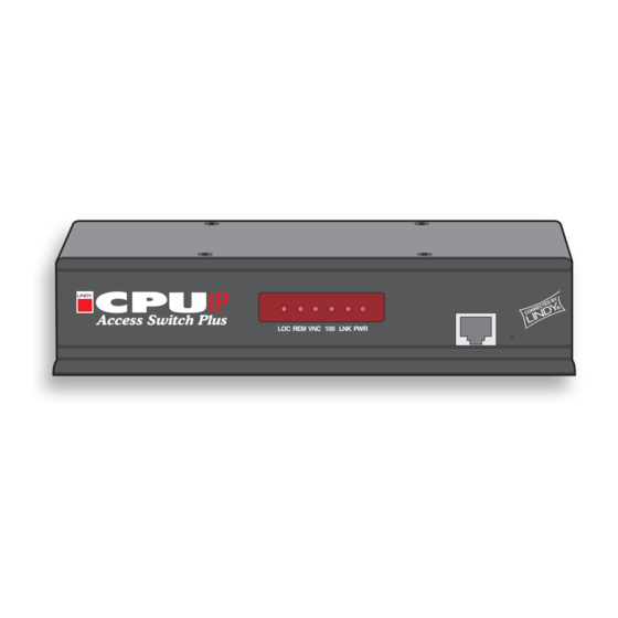
CPU IP Access Switch Plus features - front and rear Considering its capabilities, the CPU IP is supplied within a remarkably compact casing. Measuring just 198mm x 120mm x 43mm, it occupies just half of a single (1U) rack space and provides most of its connectors at the rear face. The smart front face features the IP network port and the operation indicators. -
Page 6: What's In The Box
What’s in the box CPU IP Access Switch Plus 1 0 0 CD-ROM Power supply and country- specific power lead Four Self-adhesive rubber feet KVM cable set What you may additionally need Single unit rack brackets Includes four screws Part number: 39403... -
Page 7: Installation
Installation Mounting The CPU IP offers three main mounting methods: • Supplied four self-adhesive rubber feet • Optional single unit rack brackets • Optional double unit rack brackets Connections 2 . 5 IN D 2 . 5 IN D 2 . 5 IT C 2 . -
Page 8: Connections
1 Ensure that power is disconnected from the CPU IP and the computer or KVM switch to be connected. (Note: If it is not possible to switch off devices prior to connection, then a ‘Hot plug’ procedure is available – see the restoration section for more details). -
Page 9: Local Keyboard, Video Monitor And Mouse
Local keyboard, video monitor and mouse A locally connected keyboard, video monitor and mouse are required during the initial configuration. These are also useful during normal use to allow quick local control of any connected host computers. To connect a local keyboard, video monitor and mouse 1 Position a suitable keyboard, video monitor and mouse in the vicinity of the CPU IP such that their cables will easily reach. -
Page 10: Modem/Isdn Port
Power supply connection The CPU IP is supplied with a single power supply and an appropriate country- specific IEC power lead. There is no on/off switch so operation begins as soon as the power supply is connected. To connect the power supply are employed. -
Page 11: Power Control Port
Power to computer Box 2, port 6 - address: 26 3 For each of the remaining switch boxes (if used), use a serial cable with RJ10 connectors at both ends (see end to the socket marked ‘OUT’ of the previous box and the other end to the socket marked ‘IN’... -
Page 12: Configuration
Part 1 – Local configuration When you switch on the CPU IP unit for the first time it will take you (using the locally connected keyboard and video monitor) through a set up sequence consisting of four main screens: IP Access Switch + Unit Config >... - Page 13 To perform the initial local configuration 1 Edit the Unit config screen. The key elements here are: IP Access Switch + Unit Config Hardware Rev 1 Firmware Version 1.4 Keybd Layout Admin Passwd Unit Name Hot Keys Ctrl+Alt Screensaver 10 mins...
-
Page 14: Encryption Settings
5 Once the secure keys have been calculated the CPU IP will restart and present a standard logon screen. IP Access Switch Plus Logon Username: Password: Once the username and password have been accepted, the screen should now show the host computer screen (or, if none is connected, a blank image). -
Page 15: Hot Plugging And Mouse Restoration
Hot plugging and mouse restoration It is strongly recommended that you switch off a host computer before attempting to connect it to the CPU IP. However, if this is not possible then you need to ‘hot plug’ the computer while it is still running. There is not normally a danger of damage to the computer, however, when mouse communications are interrupted, often they fail to re-initialise when reconnected. -
Page 16: Resetting The Configuration
DO YOU WISH TO CONTINUE? RESET Cancel 5 Remove power, return the mini switch 1 to its OFF position and then re- apply power. The locally connected monitor should display the first screen of initial configuration sequence. -
Page 17: Part 2 - Remote Configuration
Allows you to configure user access, hot key switching and power control codes for up to 32 host systems that may be connected to the CPU IP via KVM switch units. Shaded items signify options that are not available at the local configuration stage. -
Page 18: Networking Issues
IMPORTANT: The correct configuration of routers and firewalls requires advanced networking skills and intimate knowledge of the particular network. LINDY cannot provide specific advice on how to configure your network devices and strongly recommend that such tasks are carried out by a qualified professional. - Page 19 CPU IP at local address and net mask, i.e. 192.168.0.3 IP address: 192.168.0.3 Access Switch Plus LOC REM VNC 100 LNK PWR Net mask: 255.255.255.0 To discover a DHCP-allocated IP address Once a DHCP server has allocated an IP address, you will need to know it in order to access the CPU IP via a network connection.
-
Page 20: Placing Cpu Ip Alongside The Firewall
• Avoid accessing the CPU IP from public computers. Security can be further improved by using the following suggestions: • Use a KVM switch with On-Screen-Display driven security access and an auto- logout (after inactivity) feature to provide a second level of security. -
Page 21: Power Switching Configuration
Configuration window to store the details. Power control sequences Note: The settings given below are for the LINDY power switch - other power switches may require different settings. Please refer to your power switch documentation for details about codes required by other power switches. -
Page 22: Performing A Flash Upgrade
7 When the upload is complete and confirmed on screen, log off the remote system and then power down the CPU IP. 8 At the rear of the unit, return the mini switch 1 to its OFF position and then re-apply power. -
Page 23: Operation
The admin user has the ability to overrule the private setting. • Host - Where more than one host computer is available via the CPU IP, this option allows you to easily switch between them. Use between host computers. • Return to host - Quits the control menu and displays the host computer screen. -
Page 24: Remote Connections
From a remote system, you connect to the CPU IP using a viewer and a link. There are two types of viewer and two types of link, which can be used in any combination. Network viewer link Dial up browser link Access Switch Plus LOC REM VNC 100 LNK PWR... -
Page 25: Remote Connection By Vnc Viewer
CPU IP and its host computer(s). VNC viewer is readily available from a number of different sources: • from the CPU IP installation CD • from the CPU IP itself LINDY website • from the • from the RealVNC website To connect using the VNC viewer 1 Locate and select the VNC viewer icon ð... -
Page 26: Using The Viewer Window
Using the viewer window The viewer window gives you the ability to view and control the CPU IP and its host computer(s). Its operation is almost identical regardless of whether you used the VNC viewer or your Web browser to display it. The menu bar The viewer window presents a menu bar similar to that shown below. -
Page 27: Mouse Pointers
The Hosts button on the menu bar provides the quickest and most efficient way to switch between host computers. This is because the button is close at hand, but also because the screen calibration details for each host are reused when this method of switching is used. -
Page 28: Auto Calibrate
Once this has been done, providing you use the ‘Hosts’ button to switch between host computers, the video settings for each machine will be re-used. Note: When performing an auto calibration, ensure that the screen image is static (no moving images) and also that there are no on-screen displays generated by KVM switches (such as host names or menus). -
Page 29: Controls
Controls When clicked, this button reveals a menu of options concerned with keyboard, video and mouse operation. Resync mouse This option has the same effect as the button on the menu bar and resynchronises the local and remote mouse pointers. Refresh screen This option refreshes the whole screen image to remove any artifacts from moved screen items. - Page 30 Threshold rate than is necessary, thus worsening the screen artefacts. Setting the Threshold manually Occasionally it can be useful to manually adjust the Threshold setting, such as when there is a KVM switch OSD banner that cannot be easily removed from the display. Threshold The threshold 1 Use the ‘Calibrate all’...
-
Page 31: Connecting Via Dial Up (Modem Or Isdn) Link
Connecting via dial up (modem or ISDN) link When you use a modem or ISDN link to make the connection, the CPU IP uses standard network protocols to create a private two-device network. This approach ensures consistency and allows you to use exactly the same VNC viewer or browser to view the hosts systems. -
Page 32: Viewer Encryption Settings
Viewer encryption settings The web browser viewers and VNC viewers (of level 4.0b5S or higher) offer four encryption options. The resulting actions of certain options depend upon how the CPU IP to which you are connecting is configured: • Always on - This setting will ensure that the link is encrypted, regardless of the CPU IP encryption setting. -
Page 33: Further Information
If you are still experiencing problems after checking the list of solutions in the Troubleshooting section then we provide a number of other solutions: • LINDY website – www.lindy.com Check the Support section of our website for the latest solutions and driver files. -
Page 34: Appendix 1 - Local Configuration Menus
Back If you are not logged on as the ‘admin’ user then the Configuration menu will not be available. Use the Host entry to switch to the required host computer (when a KVM switch is used). Select the required option: •... -
Page 35: Unit Configuration
Unit configuration This page provides access IP Access Switch + Unit Config to a selection of both basic and fundamental settings Hardware for the CPU IP. Firmware Keybd Layout Admin Passwd Unit Name Hot Keys Screensaver Time Date Encryption Save... -
Page 36: Network Configuration
This is the address of the device that links the local network (to which the CPU IP is connected) to another network such as the Internet. Usually this is a network switch or router and it will be used whenever a device to be contacted lies outside the local network. -
Page 37: Modem Configuration
Modem configuration This page allows you to configure the COM1 serial port located at the rear of the CPU IP. Server IP Client IP Baud Rate Init String Save Server IP / Client IP When a user dials into the CPU IP via a modem or ISDN adapter, the CPU IP sets up a temporary two-device network using PPP (Point to Point Protocol). -
Page 38: Reset Configuration
Reset configuration This option allows you to completely reset the CPU IP. WARNING: Continuing will cause your existing configuration to be erased. The unit will then reset and require re-configuring before it can be used. DO YOU WISH TO CONTINUE? RESET WARNING: This process will remove all settings and return the unit to use its original state. -
Page 39: Clear Ip Access Control
Clear IP access control This option removes all entries from the IP access control feature within the CPU What is IP access control? The IP access control feature (configurable by a remote admin user) allows certain network address ranges to be denied access to the CPU IP. If set incorrectly, it is possible to exclude all network users and so this option provides an emergency recovery point. -
Page 40: Appendix 2 - Vnc Viewer Connection Options
Appendix 2 - VNC viewer connection options When you are connecting to the CPU IP using the VNC viewer, a number of options are available. Click here to access the options There are five tabbed pages of options: Colour/Encoding Auto select When ticked, this option will examine the speed of your connection to the CPU IP and apply... -
Page 41: Inputs
Inputs Send pointer events to server When un-ticked, the VNC viewer will not send mouse movement or click data to the CPU IP or host system. Send keyboard events to server When un-ticked, the VNC viewer will not send keyboard information to the CPU IP or host system. -
Page 42: Identities
Identities This feature helps your VNC viewer to confirm that a revisited CPU IP is genuine and not another device masquerading as a CPU IP. The list given will retain the identities of all visited CPU IP units (that have full security enabled). -
Page 43: Appendix 3 - Vnc Viewer Window Options
Appendix 3 - VNC viewer window options Click the VNC icon in the top left corner of the viewer window (or press F8) to display the window options: Standard window control items Full screen Expands the VNC viewer window to fill the whole screen with no visible window edges or toolbar. -
Page 44: Appendix 4 - Browser Viewer Options
Appendix 4 - Browser viewer options When you are connecting to the CPU IP using a Web browser, a number of options are available. Click here to access the options There is a single page of options: Encoding and colour level Auto select When ticked, this option will examine the speed of your connection to the CPU... -
Page 45: Appendix 5 - Remote Configuration Menus
Appendix 5 - Remote configuration menus This section covers the configuration menus that are available to remote admin users using either the VNC viewer or the browser methods of access. To access the remote configuration menus • Click the Configure button in the top right corner of the window when logged on as the admin user. -
Page 46: User Accounts
Internet (depending on how the CPU IP is connected). Power When ticked, the selected user will be permitted to control the power input to host systems (requires optional power control switch unit(s) to be fitted). -
Page 47: Unit Configuration
Unit configuration This page provides access to a selection of both basic and fundamental settings for the CPU IP. Many of the settings displayed here are also accessible through the on-screen menu on the locally attached keyboard, mouse and monitor. Hardware Version Indicates the version of the electronic circuitry within the CPU IP unit. -
Page 48: Advanced Unit Configuration
Advanced unit configuration Click this button to display several advanced options that do not normally require alteration. To get here 1 Using VNC viewer or a browser, log on as the ‘admin’ user. 2 Click the ‘Configure’ button in the top right corner. 3 Click the ‘Unit configuration’... -
Page 49: Network Configuration
This is the address of the device that links the local network (to which the CPU IP is connected) to another network such as the wider Internet. Usually the actual gateway is a network switch or router and it will be used whenever a required address lies outside the current network. -
Page 50: Setting Ip Access Control
Setting IP access control The golden rule with this feature is ‘Include before you exclude’ or to put it another way ‘Arrange allowed addresses in the list before the denied addresses’. This is because the positions of entries in the list are vitally important. Once a range of addresses is denied access, it is not possible to make exceptions for particular addresses within that range. -
Page 51: Serial Port Configuration
Serial port configuration This page provides all access to settings concerned with the two serial ports (modem and power control) that are situated at the rear of the CPU IP. To get here 1 Using VNC viewer or a browser, log on as the ‘admin’ user. 2 Click the ‘Configure’... -
Page 52: Host Configuration
(e.g. admin,nigel,andy,steve). Hot keys Declare the hot key sequence that will cause the KVM switch to link with the required host system. The following notations are used: ‘+‘ means press down the following key; ‘-‘ means release the following key;... -
Page 53: Logging And Status
Logging and status This screen provides various details about the user activity on the CPU IP. Date and User Access method time the name or remote IP event address occurred Click to clear Click to all log entries refresh the list To copy and paste the log You can copy the information listed within the log and paste it into another application. -
Page 54: Appendix 6 - Addresses, Masks And Ports
The important parts of the whole number depend on where you are. If you were based in the same local area as LINDY, there would be no point in dialling out of the UK, or even out of the area. The only part of the whole number that you are interested in is the final part: 754000. -
Page 55: Net Masks - The Binary Explanation
Net masks - the binary explanation To really understand the operation of a net mask it is necessary to delve deeper into the life blood of computers – binary; this is native digital, where everything is either a 1 (one) or 0 (zero), on or off, yes or no. The net mask operation described on the previous page AND function’. -
Page 56: Calculating The Mask For Ip Access Control
Calculating the mask for IP access control The IP access control function uses a standard IP address and a net mask notation to specify both single locations and ranges of addresses. In order to use this function correctly, you need to calculate the mask so that it accurately encompasses the required address(es). -
Page 57: Ports
– see IMPORTANT: The correct configuration of routers and firewalls requires advanced networking skills and intimate knowledge of the particular network. LINDY cannot provide specific advice on how to configure your network devices and strongly recommend that such tasks are carried out by a qualified professional. -
Page 58: Appendix 7 - Cable And Connector Specifications
RS232 serial mouse to PS/2 converter cable 6pin mini-DIN female -12V Female CPU IP to power switch cable 9pin D-type 9pin D-type female female Power switch to power switch daisy chain cable TXD (-12V) 4pin RJ10 4pin RJ10 4pin RJ10... -
Page 59: Appendix 8 - Hotkey Sequence Codes
Appendix 8 – Hotkey sequence codes These codes are used when defining hotkey switching sequences for host computers and allow you to include almost any of the special keys on the keyboard. Main control keys Backspace | Tab | Return | Enter | Ctrl | Alt | Win | Shift | LShift | RShift LCtrl | RCtrl | LAlt | AltGr | RAlt | LWin | RWin | Menu | Escape | Esc Math operand keys Add | Subtract | Multiply... -
Page 60: Other Products In The Cpu Switch Range
LINDY will replace or repair it free of charge. Any faulty items are to be returned to LINDY at the owner’s expense. No liability can be accepted for damage due to misuse or circumstances outside LINDY’s control. -
Page 61: Radio Frequency Energy
Radio Frequency Energy A Category 5 (or better) twisted pair cable must be used to connect the CPU IP units in order to maintain compliance with radio frequency energy emission regulations and ensure a suitably high level of immunity to electromagnetic disturbances. - Page 62 © 2004 LINDY Electronics Limited & LINDY Elektronik GmbH All trademarks are acknowledged. Release 1.0c October 2004 Great Britain & N. Ireland International & Eire LINDY Electronics Ltd LINDY International Ltd. Sadler Forster Way Sadler Forster Way Teesside Industrial Estate...
- Page 63 Advanced unit configuration connection 10 Configuration switches 4 Artifacts Connections host computer 7 on screen 25 ISDN 9 Assistance from LINDY 32 keyboard 8 Auto select 39,43 KVM switch 7 local 22 modem 9 monitor 8 Baud rate mouse 8...
- Page 64 Mouse restoration 13,14 Rack mounting 6 Mouse calibration 27 Raw 39,43 Mouse control 28 Remote configuration 16 Remote connection 23 Reset Networking issues 17 to factory defaults 15 Network configuration 35,48 Reset configuration 37 Network port Restore Defaults connecting 8 local setting 36 Net mask 21,35 RJ10 connector 10...
Need help?
Do you have a question about the CPU IP Access Switch Plus and is the answer not in the manual?
Questions and answers