Table of Contents
Advertisement
Advertisement
Table of Contents
Troubleshooting

Related Manuals for Matrix C7xi-03


Summary of Contents for Matrix C7xi-03
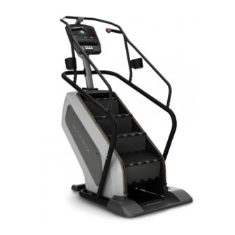
- Page 1 C 7 x i - 0 3 C l i m b m i l l S E R V i C E m A N U A l...
-
Page 2: Table Of Contents
Troubleshooting - The Time is Incorrect ..............102 Manager Mode - Weather ..................20 8.28 Troubleshooting - Unable to Boot into Matrix Home Screen ........102 Manager Mode - TV ....................21 Manager Mode - Applications ..................22 5.10 Manager Mode - Hardware .................. -
Page 3: Chapter 1: Serial Number Location
CHAPTER 1: SERiAl NUmbER loCATioN 1.1 SERiAl NUmbER loCATioN SERiAl NUmbER loCATioN... -
Page 4: Chapter 2: Important Safety Instructions
This Climb Mill is intended for commercial use. To ensure your safety * If you feel faint, stop exercising immediately. console serial number location and protect the equipment, read all instructions before operating the MATRIX Climb Mill. CAUTioN! If you experience chest pains, nausea, dizziness, or When using an electrical product, basic precautions should always be shortness of breath, stop exercising immediately and consult followed including the following: your physician before continuing. -
Page 5: Electrical Requirements
The unit is equipped with a cord having an equipment-grounding conductor and a grounding plug. The plug must be plugged into an appropriate outlet that is properly installed and grounded in accordance with all local codes and ordinances. If the user does not follow these grounding instructions, the user could void the Matrix limited warranty. AddiTioNAl ElECTRiCAl iNfo In addition to the dedicated circuit requirement, the proper gauge wire must be used from the circuit breaker box, to each outlet that will have the maximum number of units running off of it. -
Page 6: Chapter 3: Preventative Maintenance
3.2 CARE ANd mAiNTENANCE iNSTRUCTioN In order to maximize life span, and minimize down time, all MATRIX equipment requires regular cleaning, and maintenance items performed on in order to maximize life span, and minimize down time, all matrix fitness Equipment requires regularly a scheduled basis. -
Page 7: Touchscreen Care & Cleaning
CHAPTER 3: PREVENTATiVE mAiNTENANCE CHAPTER 4: CoNSolE oVERlAy ANd woRkoUT dESCRiPTioN 3.3 ToUCH SCREEN CARE & ClEANiNg 4.1 CoNSolE dESCRiPTioN ToUCH SCREEN CARE ANd ClEANiNg * The touch screen requires very little maintenance. We recommend that you periodically clean the touch screen surface with a clean dry 100% lint free cloth and water / soap mixture or a computer or LCD / LED screen cleaner. -
Page 8: Workout Setup Steps
4) Each of the tabs has options that will appear once you have chosen that particular tab. tarGet Heart rate - The Matrix Climb Mill comes with HIGH 44.2+ 41.0+ 39.5+... -
Page 9: Manager Mode - General
CHAPTER 5: mANAgER modE CHAPTER 6: mANAgER modE 5.2 mANAgER modE – gENERAl – TAb 1 5.2 mANAgER modE - gENERAl – TAb 2 mANAgER modE fUNCTioN & dEfAUlTS dESCRiPTioNS modifiEd General Date & Time This option sets the current date and time of the machine. 5.2 mANAgER modE - gENERAl –... - Page 10 CHAPTER 5: mANAgER modE CHAPTER 6: mANAgER modE 5.2 mANAgER modE – gENERAl – TAb 4 5.2 mANAgER modE - gENERAl – TAb 6 mANAgER modE fUNCTioN & dEfAUlTS dESCRiPTioNS modifiEd mANAgER modE fUNCTioN & dEfAUlTS dESCRiPTioNS modifiEd General Social Network Post This option allows the exercise time and General Software Versions...
-
Page 11: Manager Mode - Workout
CHAPTER 5: mANAgER modE CHAPTER 5: mANAgER modE 5.3 mANAgER modE - woRkoUT – TAb 1 5.3 mANAgER modE - woRkoUT – TAb 2 mANAgER modE fUNCTioN & dEfAUlTS dESCRiPTioNS modifiEd mANAgER modE fUNCTioN & dEfAUlTS dESCRiPTioNS modifiEd Workout Maximum Workout Time This option allows the club to set the Maximum: 120 Minutes Workout... -
Page 12: Manager Mode - Setup Defaults
CHAPTER 5: mANAgER modE CHAPTER 5: mANAgER modE 5.4 mANAgER modE - SETUP dEfAUlTS – TAb 1 5.4 mANAgER modE - SETUP dEfAUlTS – TAb 2 mANAgER modE fUNCTioN & dEfAUlTS dESCRiPTioNS modifiEd Setup Defaults Default Workout Floors This option controls the default program Maximum: 10000 Distance. -
Page 13: Manager Mode Asset Management
CHAPTER 5: mANAgER modE CHAPTER 5: mANAgER modE 5.6 mANAgER modE - ASSET mANAgEmENT 5.8 mANAgER modE - TV – TAb 1 mANAgER modE fUNCTioN & dEfAUlTS dESCRiPTioNS modifiEd mANAgER modE fUNCTioN & dEfAUlTS dESCRiPTioNS modifiEd Asset Management Club ID This option records the club ID of the fitness facility. -
Page 14: Manager Mode Applications
CHAPTER 5: mANAgER modE CHAPTER 5: mANAgER modE 5.8 mANAgER modE - TV – TAb 3 5.10 mANAgER modE - HARdwARE – TAb 1 mANAgER modE fUNCTioN & dEfAUlTS dESCRiPTioNS modifiEd Channel Button Setup This option is for setting the TV channel button. -
Page 15: Manager Mode Service
CHAPTER 5: mANAgER modE CHAPTER 6: ENgiNEERiNg modE 5.10 mANAgER modE - HARdwARE – TAb 2 6.1 USiNg ENgiNEERiNg modE mANAgER modE fUNCTioN & dEfAUlTS dESCRiPTioNS modifiEd Hardware Volume Basic This option controls the default volume on start Maximum: 30 Minimum: 0 1) To enter Engineering Mode, press "ENTER, 2, 0, 0, 1, ENTER"... -
Page 16: Engineering Mode General
CHAPTER 6: ENgiNEERiNg modE CHAPTER 6: ENgiNEERiNg modE 6.2 ENgiNEERiNg modE - gENERAl – TAb 1 6.2 ENgiNEERiNg modE - gENERAl – TAb 2 ENgiNEERiNg modE fUNCTioN & dEfAUlTS dESCRiPTioNS modifiEd General Date & Time This option sets the current date and time of the machine. N/A 6.2 ENgiNEERiNg modE - gENERAl –... - Page 17 CHAPTER 6: ENgiNEERiNg modE CHAPTER 6: ENgiNEERiNg modE 6.2 ENgiNEERiNg modE - gENERAl – TAb 4 6.2 ENgiNEERiNg modE- gENERAl – TAb 6 ENgiNEERiNg modE fUNCTioN & dEfAUlTS dESCRiPTioNS modifiEd ENgiNEERiNg modE fUNCTioN & dEfAUlTS dESCRiPTioNS modifiEd General Social Network Post This option allows the exercise time and General Software Versions...
-
Page 18: Engineering Mode Workout
CHAPTER 6: ENgiNEERiNg modE CHAPTER 6: ENgiNEERiNg modE 6.3 ENgiNEERiNg modE - woRkoUT – TAb 1 6.3 ENgiNEERiNg modE - woRkoUT – TAb 2 mANAgER modE fUNCTioN & dEfAUlTS dESCRiPTioNS modifiEd ENgiNEERiNg modE fUNCTioN & dEfAUlTS dESCRiPTioNS modifiEd Workout Maximum Workout Time This option allows the club to set the Maximum: 120 Minutes Workout... -
Page 19: Engineering Mode - Setup Defaults
CHAPTER 6: ENgiNEERiNg modE CHAPTER 6: ENgiNEERiNg modE 6.4 ENgiNEERiNg modE - SETUP dEfAUlTS – TAb 1 6.4 ENgiNEERiNg modE - SETUP dEfAUlTS – TAb 2 mANAgER modE fUNCTioN & dEfAUlTS dESCRiPTioNS modifiEd Default Workout Floors This option controls the default program Floors Maximum: 10000 Setup Defaults Minimum: 10... -
Page 20: Engineering Mode - Asset Management
CHAPTER 6: ENgiNEERiNg modE CHAPTER 6: ENgiNEERiNg modE 6.5 ENgiNEERiNg modE - NETwoRk – TAb 2 6.6 ENgiNEERiNg modE - ASSET mANAgEmENT ENgiNEERiNg modE fUNCTioN & dEfAUlTS dESCRiPTioNS modifiEd ENgiNEERiNg modE fUNCTioN & dEfAUlTS dESCRiPTioNS modifiEd Asset Management Club ID This option records the club ID of the Network Wired Network Setup... -
Page 21: Engineering Mode - Weather
CHAPTER 6: ENgiNEERiNg modE CHAPTER 5: ENgiNEERiNg modE 6.7 ENgiNEERiNg modE - wEATHER 6.8 ENgiNEERiNg modE - TV – TAb 2 ENgiNEERiNg modE fUNCTioN & dEfAUlTS dESCRiPTioNS modifiEd ENgiNEERiNg modE fUNCTioN & dEfAUlTS dESCRiPTioNS modifiEd Default TV Channel This option controls the default TV channel on start up. Maximum: 1000, Minimum: 2 Weather Default City... -
Page 22: Engineering Mode Applications
CHAPTER 6: ENgiNEERiNg modE CHAPTER 6: ENgiNEERiNg modE 6.9 ENgiNEERiNg modE - APPliCATioNS 6.10 ENgiNEERiNg modE - HARdwARE – TAb 1 ENgiNEERiNg modE fUNCTioN & dEfAUlTS dESCRiPTioNS modifiEd ENgiNEERiNg modE fUNCTioN & dEfAUlTS dESCRiPTioNS modifiEd Applications Application Setup This option is for setting the screen table Hardware This option controls the ErP function is Disabled Disabled or Enabled... -
Page 23: Engineering Mode Service
CHAPTER 6: ENgiNEERiNg modE CHAPTER 6: ENgiNEERiNg modE 6.10 ENgiNEERiNg modE - HARdwARE – TAb 2 6.12 ENgiNEERiNg modE - ERRoRS ENgiNEERiNg modE fUNCTioN & dEfAUlTS dESCRiPTioNS modifiEd ENgiNEERiNg modE fUNCTioN & dEfAUlTS dESCRiPTioNS modifiEd Hardware Volume Basic This option controls the default volume on start up. Maximum: 30 Errors Error Code History... - Page 24 CHAPTER 7: SERViCE modE CHAPTER 7: SERViCE modE 7.1 USiNg SERViCE modE 7.2 SERViCE modE - gENERAl - TAb 1 SERViCE modE fUNCTioN & dEfAUlTS dESCRiPTioNS modifiEd General Accumulated Time Total time on the unit since production. Cannot be modified. 1) To enter Service Mode, press "ENTER 3, 0, 0, 1, ENTER"...
-
Page 25: Chapter 7: Service Mode
CHAPTER 7: SERViCE modE CHAPTER 7: SERViCE modE 7.2 SERViCE modE - gENERAl – TAb 2 7.2 SERViCE modE - gENERAl - TAb 4 SERViCE modE fUNCTioN & dEfAUlTS dESCRiPTioNS modifiEd SERViCE modE fUNCTioN & dEfAUlTS dESCRiPTioNS modifiEd General Date & Time This option sets the current date and time of the machine. - Page 26 CHAPTER 7: SERViCE modE CHAPTER 6: SERViCE modE 7.2 SERViCE modE- gENERAl – TAb 6 7.3 SERViCE modE - woRkoUT – TAb 1 SERViCE modE fUNCTioN & dEfAUlTS dESCRiPTioNS modifiEd General Social Network Post This option allows the exercise time and distance is post to social network.
-
Page 27: Service Mode Workout
CHAPTER 7: SERViCE modE CHAPTER 7: SERViCE modE 7.3 SERViCE modE - woRkoUT – TAb 2 7.4 SERViCE modE - SETUP dEfAUlTS – TAb 1 SERViCE modE fUNCTioN & dEfAUlTS dESCRiPTioNS modifiEd SERViCE modE fUNCTioN & dEfAUlTS dESCRiPTioNS modifiEd Workout Max Cooldown Adjustment Time This option allows the club to set the Maximum: 20 Minutes... -
Page 28: Service Mode Update
CHAPTER 7: SERViCE modE CHAPTER 7: SERViCE modE 7.4 SERViCE modE - SETUP dEfAUlTS – TAb 2 7.6 SERViCE modE - NETwoRk – TAb 1 fUNCTioN & dEfAUlTS dESCRiPTioNS modifiEd SERViCE modE Default Workout Floors This option controls the default program Maximum: 10000 Setup Defaults SERViCE modE... -
Page 29: Service Mode Asset Management
CHAPTER 6: SERViCE modE CHAPTER 7: SERViCE modE 7.6 SERViCE modE - NETwoRk – TAb 3 7.7 SERViCE modE - ASSET mANAgEmENT SERViCE modE fUNCTioN & dEfAUlTS dESCRiPTioNS modifiEd SERViCE modE fUNCTioN & dEfAUlTS dESCRiPTioNS modifiEd Asset Management Club ID This option records the club ID of the fitness facility. -
Page 30: Service Mode Tv
CHAPTER 7: SERViCE modE CHAPTER 7: SERViCE modE 7.9 SERViCE modE - TV – TAb 3 7.9 SERViCE modE - TV – TAb 1 fUNCTioN & dEfAUlTS dESCRiPTioNS modifiEd SERViCE modE SERViCE modE fUNCTioN & dEfAUlTS dESCRiPTioNS modifiEd Channel Button Setup This option is for setting the TV channel button. -
Page 31: Service Mode Hardware
CHAPTER 7: SERViCE modE CHAPTER 7: SERViCE modE 7.11 SERViCE modE - HARdwARE – TAb 1 7.11 SERViCE modE - HARdwARE – TAb 2 SERViCE modE fUNCTioN & dEfAUlTS dESCRiPTioNS modifiEd SERViCE modE fUNCTioN & dEfAUlTS dESCRiPTioNS modifiEd Hardware This option controls the ErP function is Disabled or Enabled Hardware Small LCD Reversed... -
Page 32: Service Mode Virtual Active
CHAPTER 7: SERViCE modE CHAPTER 7: SERViCE modE 7.11 SERViCE modE - HARdwARE – TAb 3 7.12 SERViCE modE - ViRTUAl ACTiVE SERViCE modE fUNCTioN & dEfAUlTS dESCRiPTioNS modifiEd SERViCE modE fUNCTioN & dEfAUlTS dESCRiPTioNS modifiEd Volume Advanced This option controls the default volume on Virtual Active Root Path This option can set the Virtual Active root path. -
Page 33: Service Mode Service
CHAPTER 7: SERViCE modE CHAPTER 7: SERViCE modE 7.14 SERViCE modE - SERViCE 7.16 SERViCE modE - NETPUlSE SERViCE modE fUNCTioN & dEfAUlTS dESCRiPTioNS modifiEd SERViCE modE fUNCTioN & dEfAUlTS dESCRiPTioNS modifiEd Service Service History This option allows the club to record key Netpulse Test network and netpulse install. -
Page 34: Matrix Fitness 7Xi Series Feature Access Codes
CHAPTER 8: TRoUblESHooTiNg 7.17 mATRix fiTNESS 7xi SERiES fEATURE ACCESS CodES 8.1 ElECTRiCAl diAgRAmS This document defines the supported feature access codes for the Matrix Fitness 7xi series fitness equipment. Instruction All codes are entered in by: Press the “Enter” key. - Page 35 CHAPTER 8: TRoUblESHooTiNg CHAPTER 8: TRoUblESHooTiNg 8.1 ElECTRiCAl diAgRAmS - CoNTiNUEd 8.1 ElECTRiCAl diAgRAmS - CoNTiNUEd P01 - digiTAl CommUNiCATioN wiRE P13- SPEEd SENSoR ExTENSioN wiRE...
- Page 36 CHAPTER 8: TRoUblESHooTiNg CHAPTER 8: TRoUblESHooTiNg 8.1 ElECTRiCAl diAgRAmS - CoNTiNUEd 8.1 ElECTRiCAl diAgRAmS - CoNTiNUEd P27 - HANd PUlSE wiRES P31 - PRoximiTy SENSoR wiRE P04 - ECb loAd wiRE...
- Page 37 CHAPTER 8: TRoUblESHooTiNg CHAPTER 8: TRoUblESHooTiNg 8.1 ElECTRiCAl diAgRAmS - CoNTiNUEd 8.1 ElECTRiCAl diAgRAmS - CoNTiNUEd P19 - PowER SENSoR wiRE g18 - H/P CoNNECT wiRE P18 - CoNTRol ZoNE SENSoR wiRE P51 - iR SENSoR wiRE...
-
Page 38: Chapter 8: Troubleshooting
CHAPTER 8: TRoUblESHooTiNg CHAPTER 8: TRoUblESHooTiNg 8.2 lCb ERRoR iNdiCAToRS 8.2 lCb ERRoR iNdiCAToRS - CoNTiNUEd Status lEd Firmware definition --------------------------------------------------------------------------------- ---------------------------------------------------------------------------------- lEd STATUS dESCRiPTioN LED1 LCB status (blinking: OK). LED2 Start or Stop( bright: start ) LED3 Safety stop ( bright: action ) LED4 Safety Key action status ( bright: trigger ) LED5... -
Page 39: Ucb Wiring Connections
CHAPTER 8: TRoUblESHooTiNg CHAPTER 8: TRoUblESHooTiNg 8.3 UCb wiRiNg CoNNECTioNS 8.4 ERRoR CodE TRoUblESHooTiNg - 01AC ERRoR CodE 01AC 1) SymPTom: a. 01AC - Electro magnet (ECB) over current. 2) SolUTioN: a. On standby mode, measure the resistance on ECB1 and ECB2. Please check the ECB extension cable connection at the LCB (pins 1 & 3 for ECB1, pins 2 &... -
Page 40: Error Code Troubleshooting - 01Af
CHAPTER 8: TRoUblESHooTiNg CHAPTER 8: TRoUblESHooTiNg 8.5 ERRoR CodE TRoUblESHooTiNg - 01Af 8.6 ERRoR CodE TRoUblESHooTiNg - 02A0 ERRoR CodE 02A0 ERRoR CodE 01Af 1) SymPTom: 1) SymPTom: a. 01AF - Electro magnet (ECB) disconnected. a. 02A0 - Encoder error. b. -
Page 41: Error Code Troubleshooting - 02Be / 02Bf
CHAPTER 8: TRoUblESHooTiNg CHAPTER 8: TRoUblESHooTiNg 8.7 ERRoR CodE TRoUblESHooTiNg - 02bE / 02bf 8.8 ERRoR CodE TRoUblESHooTiNg - 02Co ERRoR CodE 02bE / 02bf ERRoR CodE 02C0 1) SymPTom: 1) SymPTom: a. 02BE - DC brake error (If movement is detected when the brake is in stop mode). a. -
Page 42: Error Code Troubleshooting - 02C1
CHAPTER 8: TRoUblESHooTiNg CHAPTER 8: TRoUblESHooTiNg 8.9 ERRoR CodE TRoUblESHooTiNg - 02C1 8.10 ERRoR CodE TRoUblESHooTiNg - 02C2 ERRoR CodE 02C1 ERRoR CodE 02C2 (Control Zone 3 iR sensors error) 1) SymPTom: 1) SymPTom: a. 02C1 -Speed tracking error (the speed tracking is off by at least 10 rpms for a continuous 20 sec). a. -
Page 43: Error Code Troubleshooting - 02C3
CHAPTER 8: TRoUblESHooTiNg CHAPTER 8: TRoUblESHooTiNg 8.11 ERRoR CodE TRoUblESHooTiNg - 02C3 8.12 ERRoR CodE TRoUblESHooTiNg - 04A0 ERRoR CodE 02C3 (frame iR sensors error) ERRoR CodE 04A0 1) SymPTom: 1) SymPTom: a. 04A0 - UCB has no communication or is disconnected. a. -
Page 44: Error Code Troubleshooting - 04B0
CHAPTER 8: TRoUblESHooTiNg CHAPTER 8: TRoUblESHooTiNg 8.13 ERRoR CodE TRoUblESHooTiNg - 04b0 8.14 TRoUblESHooTiNg - HEART RATE iSSUES ERRoR CodES 04b0 HEART RATE iSSUES 1) SymPTom: 1) SymPTom: a. No heart rate. a. 04B0 - LCB no communication response for over 3 seconds. . b. - Page 45 If your problem is not with the HR grips, a continuity check should be performed on the unit to verify that the console is properly grounded (see Service Bulletin – Continuity Test on Matrix Climb Mills). - Once the console grounding has been verified, the heart rate board ground wire should be verified.
-
Page 46: Troubleshooting - Toggle Issues
CHAPTER 8: TRoUblESHooTiNg CHAPTER 8: TRoUblESHooTiNg 8.15 TRoUblESHooTiNg - TogglE iSSUES 8.15 TRoUblESHooTiNg - TogglE iSSUES - CoNTiNUEd TogglE iSSUES - Remove the 2 screws going into the handlebar connection frame from the bottom (Figure E). - Remove the 3 screws going into the handlebar connection frame from the top (Figure F). 1) SymPTom: a. -
Page 47: Tv Troubleshooting - Overview
If this reading is higher than 1 or if there is not a reading, replace this section of grip wiring. The Matrix 7xe console includes an integrated TV that shows in the large display window. The TV is capable of being shown as a 7" or 15"... -
Page 48: Tv Troubleshooting - Picture Fuzzy Or Unclear
CHAPTER 8: TRoUblESHooTiNg CHAPTER 8: TRoUblESHooTiNg 8.17 TV TRoUblESHooTiNg - PiCTURE fUZZy oR UNClEAR 8.18 TV TRoUblESHooTiNg - TV will NoT TURN oN 1) For a fuzzy or unclear picture, see the TV programming instructions in Section 10. If the TV is still fuzzy or unclear after programming: 1) Remove the console back and check the electrical connections for the TV (Figures A &... -
Page 49: Tv Troubleshooting - Entertainment Keypad Issues
5. Plug your router back in and try to view the On Demand program again. 6. If the Netpulse gateway still doesn’t connect, the Matrix Fitness 7xi needs to get sync up and running. 7. Open the 7xi Service Mode screen. Press the Enter key, 3-0-0-1, Enter key. -
Page 50: Troubleshooting - Unable To Access The Internet
(Wired Connection) Turn off the console. To connect any devices with a wire, simply plug the Ethernet cable from the output jack of the Ethernet hub or switch to the Matrix Fitness 7xi, no passwords will be required for wired connection. -
Page 51: Troubleshooting - Black Screen Or Initializing Tv In The Tv App
Black screen in the TV APP preview window (Figure A). The console does not detect a device or cable connected to it. Check that the coaxial cable from the wall outlet to the Matrix Fitness 7xi is connected properly and firm. -
Page 52: Troubleshooting - Virtual Active Content Not Found
If the user and register buttons are still unresponsive, go to section 8.18, No Netpulse Network Connectivity. Verify the USB Flash Drive is installed into the USB Drive Port inside of the Matrix 7xi console. If you have performed all procedures described in section 8.18, No Netpulse Network Connectivity and the buttons still not work, then replace Go to 7xi Service Mode screen. -
Page 53: Troubleshooting - Bootmgr Error
2) SolUTioN: The message “Loading…” appears when your Matrix 7xi device loads a new map or when your device is not connected to the network. The following may be reasons for this error if your system has encountered the “BOOTMGR is missing” error shortly after the console is If the message “Loading…”... -
Page 54: Troubleshooting - The Time Is Incorrect
UNAblE To booT iNTo mATRix HomE SCREEN 1) SymPTom: 4) Remove the 3 screws and remove the small Matrix logo cover at the top of the stairs (Figures C & D). Unable to Boot into Matrix Home screen. You are unable to boot normally due to file system errors (data corruption and loss). -
Page 55: Console Replacement
9.1 SidE CoVER REPlACEmENT - CoNTiNUEd 9.2 CoNSolE REPlACEmENT 5) Rotate the 2 plastic clips counter-clockwise to remove the Matrix logo cover (Figures E & F). 1) Turn off power and disconnect the cord from the machine. 2) Remove the 5 screws that hold the console to the console mast (Figure A). -
Page 56: Console Overlay / Keypad Replacement
CHAPTER 9: PART REPlACEmENT gUidE CHAPTER 9: PART REPlACEmENT gUidE 9.3 CoNSolE kEyPAd / oVERlAy REPlACEmENT 9.3 CoNSolE kEyPAd / oVERlAy REPlACEmENT - CoNTiNUEd 6) Push the overlay / keypad ribbon cable through the hole in the console and plug it in (Figure E). note: The instructions below are for console overlays / keypads replacement, but the procedure is the same regardless of where the overlay / 7) Match the overlay / keypad to the cutout in the console (Figure F). -
Page 57: Front Shroud Replacement
CHAPTER 9: PART REPlACEmENT gUidE CHAPTER 9: PART REPlACEmENT gUidE 9.4 fRoNT SHRoUd REPlACEmENT 9.4 fRoNT SHRoUd REPlACEmENT - CoNTiNUEd 1) Turn off power and disconnect the cord from the machine. 8) Disconnect the hand pulse and quick key cables on the inside of the console mast (Figure E). 2) Remove all of the cables from the front cover (Figure A). -
Page 58: Lower Control Board (Lcb) Replacement
CHAPTER 9: PART REPlACEmENT gUidE CHAPTER 9: PART REPlACEmENT gUidE 9.5 lowER CoNTRol boARd (lCb) REPlACEmENT 9.6 UPPER HANdlEbAR REPlACEmENT 1) Turn off power and disconnect the cord from the machine. 1) Turn off power and disconnect the cord from the machine. 2) Remove all wiring from the front cover and remove it from the machine as outlined in Section 9.4. - Page 59 CHAPTER 9: PART REPlACEmENT gUidE CHAPTER 9: PART REPlACEmENT gUidE 9.6 UPPER HANdlEbAR REPlACEmENT SET - CoNTiNUEd 9.7 lowER HANdlEbAR SET REPlACEmENT 6) Disconnect the wire that connects the left hand grip cable to the hand pulse extension wire (Figure E). 1) Turn off the power and disconnect the cord from the machine.
-
Page 60: Handlebar Service
CHAPTER 9: PART REPlACEmENT gUidE CHAPTER 9: PART REPlACEmENT gUidE 9.8 HANdlEbAR SERViCE 9.9 STAiR REPlACEmENT 1) Turn off the power and disconnect the cord from the machine. 1) Turn off power and disconnect the cord from the machine. 2) All items on the handlebar are removed using a Phillips screwdriver from the underside of the bar. 2) Remove the side covers as outlined in Section 9.1. -
Page 61: Drive Set Replacement
2) Turn the 2 plastic screws counter-clockwise and remove the Matrix logo covers on both sides of the machine. 3) Turn the brake lever to the right to lock the stairs (Figure A) to prevent movement that could cause injury. -
Page 62: Chain Replacement
CHAPTER 9: PART REPlACEmENT gUidE CHAPTER 9: PART REPlACEmENT gUidE 9.10 dRiVE SET REPlACEmENT - CoNTiNUEd 9.11 CHAiN REPlACEmENT 9) While a tech is pushing the drive set towards the front of the unit (the drive set will still be supported by the guide screw - Figure G), the other 1) Turn off the power and disconnect the cord from the machine. -
Page 63: Brake Replacement
1) Turn off the power and disconnect the cord from the machine. 9) The chain can now be removed. 2) Remove the Matrix logo covers from each side of the machine. 3) Turn the brake lever to the right to lock the stairs and prevent movement that could cause injury. -
Page 64: Fan Replacement
2) Remove the Matrix logo covers from each side of the machine. 2) Rotate the 2 plastic clips counter-clockwise to remove the Matrix logo cover (Figures A & B). 3) Turn the brake lever to the right to lock the stairs and prevent movement that could cause injury. -
Page 65: Drive Belt Replacement
CHAPTER 9: PART REPlACEmENT gUidE CHAPTER 9: PART REPlACEmENT gUidE 9.15 dRiVE bElT REPlACEmENT 9.16 ECb REPlACEmENT 1) Turn off power and disconnect the cord from the machine. 1) Turn off power and disconnect the cord from the machine. 2) Remove the drive set as outlined in Section 9.10. 2) Follow the steps outlined in Section 8.4 to test the new ECB before installing it. -
Page 66: Speed Sensor Replacement
9) There should be 4 screws & ferrules remaining to mount the new ECB (Figure F). 2) Rotate the 2 plastic clips counter-clockwise to remove the left side Matrix logo cover. 3) Disconnect the speed sensor wire (Figure A). note: Use 2 hands to disconnect the speed sensor wire. Do not pull the socket downwards to disconnect as it will damage the connector. -
Page 67: Proximity Sensor Replacement
2) Pull up on the Control Zone carefully (Figure A). 2) Rotate the 2 plastic clips counter-clockwise to remove the left side Matrix logo cover. 3) Unplug the wire from the Control Zone and remove the Control Zone from the unit (Figure B). -
Page 68: Ir Sensor Replacement
8) Remove the IR sensor with plate from frame (Figure E). 2) Remove the Matrix logo covers from each side of the machine. 9) Remove the 2 screws holding the IR sensor to the plate (Figure F) and remover the IR sensor. -
Page 69: Cf Card Replacement
If the CF card has been used in a different 7xi console, it cannot be reused in another console. To reuse a CF card, it needs to 1. Remove the back cover of the console (Figure A). go through a special process by the Matrix Service Team. 2. Remove all the cables and CF card (Figure B). 1) Turn on the power to the Climb Mill , wait until the welcome display picture has been come up (Figure A). -
Page 70: Testing The Climb Mill
CHAPTER 9: PART REPlACEmENT gUidE CHAPTER 9: PART REPlACEmENT gUidE 9.22 CoNSolE PARTS REPlACEmENT - CoNTiNUEd 9.23 TESTiNg THE Climb mill oNCE THE UNiT oR REPlACEmENT PART iS fUlly iNSTAllEd ANd ASSEmblEd ANd 7. Remove the TV tuner (Figure G). 8. -
Page 71: Chapter 10: Climb Mill Specifications And Assembly Guide
CHAPTER 10: Climb mill SPECifiCATioNS ANd ASSEmbly gUidE CHAPTER 10: Climb mill SPECifiCATioNS ANd ASSEmbly gUidE 10.1 Climb mill SPECifiCATioNS 10.2 ASSEmbly HARdwARE C7xi CLIMBMILL QUANTiTy SkETCH dESCRiPTioN PACkAgE ColoR Features SOCKET HEAD SCREW BLACK (M8 X 25L) STEP HEIGHT 10”... -
Page 72: Climb Mill Assembly Steps
CHAPTER 10: Climb mill SPECifiCATioNS ANd ASSEmbly gUidE CHAPTER 10: Climb mill SPECifiCATioNS ANd ASSEmbly gUidE 10.3 Climb mill ASSEmbly STEPS 10.3 Climb mill ASSEmbly STEPS - CoNTiNUEd STEP 1 - blACk HARdwARE bAg STEP 2 - blUE & gREEN HARdwARE bAgS 1) Open the Blue and Green hardware bags. - Page 73 CHAPTER 10: Climb mill SPECifiCATioNS ANd ASSEmbly gUidE CHAPTER 10: Climb mill SPECifiCATioNS ANd ASSEmbly gUidE 10.3 Climb mill ASSEmbly STEPS - CoNTiNUEd 10.3 Climb mill ASSEmbly STEPS - CoNTiNUEd STEP 3 - CoNSolE STEP 4 - bASE STEP 1) Connect the wires from the Base Frame to the Base Step. 1) Remove the five pre-attached console screws from the back of the console.
-
Page 74: Stabilizing The Climb Mill
Once the cardio equipment has been installed and proper power and cable wiring is provided, The Television must be programmed to the club's channels and settings. The Matrix Climb Mill should be level for optimum use. Locate a level, stable surface to position the equipment. The equipment has leveling Auto Tuning - An auto scan will search for channel signals from the coax cable. -
Page 75: Tv Programming Instructions
CHAPTER 10: Climb mill SPECifiCATioNS ANd ASSEmbly gUidE CHAPTER 10: Climb mill SPECifiCATioNS ANd ASSEmbly gUidE 10.5 TV PRogRAmmiNg iNSTRUCTioNS (US) - CoNTiNUEd 10.5 TV PRogRAmmiNg iNSTRUCTioNS (US) - CoNTiNUEd Auto Tuning (continued): Auto Tuning (continued): 7. The achieved scan will be displayed on the bottom left hand corner of the screen (Figure G). Once the channel scan is complete, the scanned channels will be displayed on the channel list on the screen (Figure H). - Page 76 CHAPTER 10: Climb mill SPECifiCATioNS ANd ASSEmbly gUidE CHAPTER 10: Climb mill SPECifiCATioNS ANd ASSEmbly gUidE 10.5 TV PRogRAmmiNg iNSTRUCTioNS (id mARkET) - wiTH THE THE HAUPPAUgE TV TUNER 10.5 TV PRogRAmmiNg iNSTRUCTioNS (id mARkET) - wiTH THE HAUPPAUgE TV TUNER - CoNTiNUEd Once the cardio equipment has been installed and propered power and cable wiring is provided, The Television must be programmed to the club's Auto Tuning (continued): channels and settings.
- Page 77 CHAPTER 10: Climb mill SPECifiCATioNS ANd ASSEmbly gUidE CHAPTER 10: Climb mill SPECifiCATioNS ANd ASSEmbly gUidE 10.5 TV PRogRAmmiNg iNSTRUCTioNS (id mARkET) - wiTH THE HAUPPAUgE TV TUNER - CoNTiNUEd 10.5 TV PRogRAmmiNg iNSTRUCTioNS (id mARkET) - wiTH THE AVERmEdiA TV TUNER Once the cardio equipment has been installed and proper powered and cable wiring is provided, The Television must be programmed to the club's channels and settings.
- Page 78 CHAPTER 10: Climb mill SPECifiCATioNS ANd ASSEmbly gUidE CHAPTER 10: Climb mill SPECifiCATioNS ANd ASSEmbly gUidE 10.5 TV PRogRAmmiNg iNSTRUCTioNS (id mARkET) - wiTH THE AVERmEdiA TV TUNER - CoNTiNUEd 10.5 TV PRogRAmmiNg iNSTRUCTioNS (id mARkET) - wiTH THE AVERmEdiA TV TUNER - CoNTiNUEd Auto Tuning (continued): Auto Tuning (continued): 7.
-
Page 79: Using Update Manager
CHAPTER 10: Climb mill SPECifiCATioNS ANd ASSEmbly gUidE CHAPTER 10: Climb mill SPECifiCATioNS ANd ASSEmbly gUidE 10.5 TV PRogRAmmiNg iNSTRUCTioNS (id mARkET) - wiTH THE AVERmEdiA TV TUNER - CoNTiNUEd 10.6 USiNg UPdATE mANAgER Auto Tuning (continued): 12. The scanning progress will be displayed on the bottom left hand corner of the screen (Figure P). Once the channel scan is complete, the scanned channels will be displayed on the channel list on the screen (Figure q). - Page 80 CHAPTER 10: Climb mill SPECifiCATioNS ANd ASSEmbly gUidE CHAPTER 10: Climb mill SPECifiCATioNS ANd ASSEmbly gUidE 10.6 UPdATE mANAgER - iNSTAllEd UPdATES – TAb 1 10.6 UPdATE mANAgER - UPdATE HiSToRy – TAb 3 mANAgER modE fUNCTioN & dEfAUlTS dESCRiPTioNS modifiEd mANAgER modE fUNCTioN &...
- Page 81 Please note that this guide is meant to provide an overview on the configuration and setup steps that are unique to the 7xi product. The equipment itself is assembled and installed almost identically to the Matrix Fitness 7xe product line. What sets the Matrix Fitness 7xi equipment apart is our new ‘app’...
- Page 82 5. Fill out all necessary information and select ‘Add.’ A new facility ID will be provided for the facility (Figure E). Every order for Matrix Fitness 7xi product includes access to the Matrix Fitness Asset Management Website. At the time the sales order is placed, a new facility ID is created and assigned to the facility.
- Page 83 2. Select ‘Facility list’ from the CTS dropdown menu at the top of the Screen. Search your facility and remember your club ID. Then enter upload logo (Figure A). 3. Upload club logo into Matrix Fitness Asset Management site (Figure B). figURE A...
- Page 84 10.7.2 Setting up wired and wireless Connections in a facility 2. install gateway server and switch introduction: Each facility has two options for the network setup on their Matrix Fitness 7xi product: a. Connect the modem to the Gateway with a patch cable.
- Page 85 CHAPTER 10: Climb mill SPECifiCATioNS ANd ASSEmbly gUidE CHAPTER 10: Climb mill SPECifiCATioNS ANd ASSEmbly gUidE 10.7 NETPUlSE & Am SETTiNg UP SoP 10.7 NETPUlSE & Am SETTiNg UP SoP 3. wire club with Ethernet A wireless connecting solution option 2: The media Gateway is connected to a local internet source.
- Page 86 CHAPTER 10: Climb mill SPECifiCATioNS ANd ASSEmbly gUidE CHAPTER 10: Climb mill SPECifiCATioNS ANd ASSEmbly gUidE 10.7 NETPUlSE & Am SETTiNg UP SoP 10.7 NETPUlSE & Am SETTiNg UP SoP STEP 1 - Identifying areas that need coverage and estimating the number of APs needed: Wireless coverage only needs to be provided in areas where cardio machines need to have a wireless connection.
- Page 87 CHAPTER 10: Climb mill SPECifiCATioNS ANd ASSEmbly gUidE CHAPTER 10: Climb mill SPECifiCATioNS ANd ASSEmbly gUidE 10.7 NETPUlSE & Am SETTiNg UP SoP 10.7 NETPUlSE & Am SETTiNg UP SoP Examples of bAd AP coverage With this type of coverage pattern it is very important to mount the AP so that the base of the coverage cone covers the desired wireless clients. This can be accomplished by mounting the AP to the ceiling above the clients with the face of the AP (the side with the LED lights) pointed down toward the floor.
- Page 88 Ethernet Cable. Select the Network to obtain the network setting screen, press the right / left arrow to switch the screen to wired network setup Upon completing the install of the Matrix Fitness 7xi cardio equipment, it will be necessary to connect the consoles to the media gateway that is screen (Figure D).
- Page 89 CHAPTER 10: Climb mill SPECifiCATioNS ANd ASSEmbly gUidE CHAPTER 10: bikE SPECifiCATioNS ANd ASSEmbly gUidE 10.7 NETPUlSE & Am SETTiNg UP SoP 10.7 NETPUlSE & Am SETTiNg UP SoP 3. Access Point setting c. Wireless Solutions (With general AP setting & without Meraki AP - MR12 or MR24) a.
- Page 90 CHAPTER 10: Climb mill SPECifiCATioNS ANd ASSEmbly gUidE CHAPTER 10: Climb mill SPECifiCATioNS ANd ASSEmbly gUidE 10.7 NETPUlSE & Am SETTiNg UP SoP 10.7 NETPUlSE & Am SETTiNg UP SoP Set the NAT mode: Use Meraki DHCP. Set the NAT mode: Use Meraki Bridge mode. ii.
-
Page 91: Chapter 11: Software Upgrade Procedure
CHAPTER 11: SofTwARE UPgRAdE iNSTRUCTioNS CHAPTER 11: SofTwARE UPgRAdE iNSTRUCTioNS 11.1 SofTwARE UPgRAdE PRoCEdURE fRom wEbSiTE 11.1 SofTwARE UPgRAdE PRoCEdURE fRom wEbSiTE - CoNTiNUEd 8) Press the Install All Updates key on the screen (Figure D). 9) Press the Yes key to auto run the upgrade process (Figure E). NOTE: Don’t power off the machine while the software is being installed. After the software has been installed completely, turn off the machine and wait 30 seconds, then turn the machine back on. If the display shows 04A0, turn off & turn on the machine again. -
Page 92: Software Upgrade Procedure From Usb
CHAPTER 11: SofTwARE UPgRAdE iNSTRUCTioNS CHAPTER 11: SofTwARE UPgRAdE iNSTRUCTioNS 11.2 SofTwARE UPgRAdE PRoCEdURE fRom USb 11.2 SofTwARE UPgRAdE PRoCEdURE fRom USb - CoNTiNUEd 9) Press the Available Updates key on the screen (Figure E). NOTE: Don’t power off the machine while the software is being installed. After the software has been installed completely, turn off the machine and wait 30 seconds, then turn the machine back on. If the display shows 04A0, turn off & turn on the machine again. 1) Copy the Picard software onto the USB drive (Figure A). 2) Turn on the power to the Climb Mill, wait until the welcome display picture has been come up (Figure B). -
Page 93: Software Upgrade Procedure For Lcb
CHAPTER 11: SofTwARE UPgRAdE iNSTRUCTioNS CHAPTER 11: SofTwARE UPgRAdE iNSTRUCTioNS 11.2 SofTwARE UPgRAdE PRoCEdURE fRom USb - CoNTiNUEd 11.3 SofTwARE UPgRAdE PRoCEdURE foR lCb NOTE: 1. In order update LCB from console, the 7xi software should be upgraded to 2.3 or above first. 2. 14) Enter Service Mode by pressing ENTER, 3, 0, 0, 1, ENTER on the lower keypad and check that the Machine Type is correctly set for S7xi. - Page 94 CHAPTER 11: SofTwARE UPgRAdE iNSTRUCTioNS 11.3 SofTwARE UPgRAdE PRoCEdURE foR lCb - CoNTiNUEd NoTES 5) The screen will show every software install status (Figure G). When the update is completed, turn off the machine and wait 30 sec, then turn on the machine (Figure H).
- Page 95 ES S Sy S TE mS C o R P. 1610 LANDM ARK DR I VE C OTTA GE G R OV E WI 535 27 U S A TOLL FREE 866.693.4863 ww w.m atr i xfi tn es s . co m FA X 60 8.8 39 .1 717...
Need help?
Do you have a question about the C7xi-03 and is the answer not in the manual?
Questions and answers