OLIMEX OLinuXino-MAXI User Manual
Single-board linux computer
Hide thumbs
Also See for OLinuXino-MAXI:
- User manual (60 pages) ,
- User manual (48 pages) ,
- User manual (47 pages)
Table of Contents
Advertisement
Quick Links
Download this manual
See also:
User Manual
Advertisement
Table of Contents

Related Manuals for OLIMEX OLinuXino-MAXI


Summary of Contents for OLIMEX OLinuXino-MAXI
- Page 1 OLinuXino-MAXI single-board Linux computer USER’S MANUAL Initial release, May 2012 Designed by OLIMEX Ltd, 2012 All boards produced by Olimex LTD are ROHS compliant...
- Page 2 This document is intended only to assist the reader in the use of the product. OLIMEX Ltd. shall not be liable for any loss or damage arising from the use of any information in this document or any error or omission in such information or any incorrect use of the product.
-
Page 3: Table Of Contents
OLIMEX© 2012 OLinuXino User's Manual Table of Contents CHAPTER 1.........................5 OVERVIEW.........................5 1. Introduction to the chapter.......................5 1.1 Features.............................5 1.2 The OLinuXino family......................6 1.2 Target market and purpose of the board................6 1.3 Organization..........................6 CHAPTER 2 ........................8 SETTING UP THE OLINUXINO BOARD..............8 2. - Page 4 OLIMEX© 2012 OLinuXino User's Manual 6.2 SD/MMC slot..........................23 6.3 UEXT module.........................24 6.4 GPIO (General Purpose Input/Output) 40pin connector ..........25 6.5 USB HOSTs..........................28 6.6 LAN connector........................29 6.7 PWR Jack..........................30 6.8 Headphones and line-in connector..................30 6.9 Battery connector........................31 6.10 Composite video connector....................32 6.11 Boot mode positions......................32...
-
Page 5: Chapter 1
Thank you for choosing the OLinuXino single board computer from Olimex! This document provides a user’s guide for the Olimex OLinuXino board. As an overview, this chapter gives the scope of this document and lists the board’s features. The differences between the members of the OLinuXino family are mentioned. -
Page 6: The Olinuxino Family
OLIMEX© 2012 OLinuXino User's Manual 1.2 The OLinuXino family Table of comparison OLinuXino-MICRO OLinuXino-MINI OLinuXino-MAXI Processor iMX233 @ 454Mhz iMX233 @ 454Mhz iMX233 @ 454Mhz Ram [MB] # USB hosts 100 Mbit Ethernet No/WIFI option* GPIO connector 60pins 40pins 40pins... - Page 7 OLIMEX© 2012 OLinuXino User's Manual microcontroller – Chapter 5 is an explanation of the control circuitry associated with the microcontroller to reset. Also shows the clocks on the board – Chapter 6 covers the connector pinout, peripherals and jumper description –...
-
Page 8: Chapter 2
Note that the board arrives without SD card or Linux image. You can purchase a card with Linux separately. It is recommended that the user has basic Linux experience. Some of the suggested items can be purchased by Olimex, for instance: iMX233-OLinuXino-SD - SD card with the Linux image USB-SERIAL-CABLE - USB serial console cable SY0612E - power supply adapter 12V/0.5A for iMX233-OLinuXino-Maxi... -
Page 9: Powering The Board
OLIMEX© 2012 OLinuXino User's Manual 2.4 Powering the board The board is powered either via the PWR jack or via a battery. It should be supplied from a 6V to 16V source with maximum current of 1A from the power jack. - Page 10 OLIMEX© 2012 OLinuXino User's Manual instructions on how the Linux image can be created will be added to this guide at a later time. To ensure you have the latest Linux version supported with all the updates visit https://github.com/OLIMEX/OLINUXINO https://github.com/Freescale/fsl-community-bsp- platform.
-
Page 11: Chapter 3
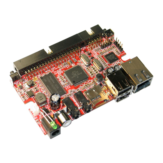
OLIMEX© 2012 OLinuXino User's Manual CHAPTER 3 OLINUXINO BOARD DESCRIPTION 3. Introduction to the chapter Here you get acquainted with the main parts of the board. Note the names used on the board differ from the names used to describe them. For the actual names check the OLinuXino board itself. -
Page 12: Chapter 4
OLIMEX© 2012 OLinuXino User's Manual CHAPTER 4 THE iMX233 MICROCONTROLLER 4. Introduction to the chapter In this chapter is located the information about the heart of OLinuXino – its microcontroller. The information is a modified version of the datasheet provided by its manufacturers. - Page 13 OLIMEX© 2012 OLinuXino User's Manual — Amplifiers are designed for click/pop free operation. — Two stereo line inputs — Microphone input — SPDIF digital out 16-Channel Low-Resolution ADC — 6 independent channels and 10 dedicated channels — Resistive touchscreen controller —...
- Page 14 OLIMEX© 2012 OLinuXino User's Manual Pixel Processing Pipeline (PXP) — Provides full path from color-space conversion, scaling, alpha-blending to rotation without intermediate memory access — Bi-linear scaling algorithm with cropping and letterboxing — Alpha-blend, BITBLT, color-keying — Memory efficient block-based rotation engine —...
- Page 15 OLIMEX© 2012 OLinuXino User's Manual — Analog I/O for peripheral bus breakouts — I S, left-justified, right-justified, and non-standard formats Customer-Programmable One-Time-Programmable (OTP) ROM via Integrated eFuse Block — Resistor-less boot mode selection — 128-bit boot mode crypto key —...
-
Page 16: Chapter 5
OLIMEX© 2012 OLinuXino User's Manual CHAPTER 5 CONTROL CIRCUITY AND HARDWARE MODULES 5. Introduction to the chapter Here you can find information about reset circuit and quartz crystals locations, the power supply circuit is discussed. 5.1 Reset OLinuXino's reset circuit includes R9 (47KΩ), R10 (47 Ω), T1, T2, Q1 and a RESET button. The RESET is specific for the fact that it is accomplished when the quarz is disconnected using 3.3V... -
Page 17: Power Supply Circuit
OLinuXino User's Manual 5.3 Power supply circuit The power supply circuit of OLinuXino-MAXI allows flexible input supply from 6V to 16V direct current. This means a wide range of power supplies, adapters, converters are applicable. The maximum amperage recommended is 1A by default (0.250mA if 3.3VIO_E is closed – read below). - Page 18 OLIMEX© 2012 OLinuXino User's Manual The jumper 5V_E (5V Enable) which is closed by default enables powering the board via the power supply circuit. The 3.3V_E (3.3V Enable) jumper when closed enables the 3.3V power line. Note the 3.3VIO_E jumper which by default is closed – it disables the U6 DC-DC converter and enables a built-in the iMX233 DC-DC.
-
Page 19: Chapter 6
OLIMEX© 2012 OLinuXino User's Manual CHAPTER 6 CONNECTORS AND PINOUT 6. Introduction to the chapter In this chapter are presented the connectors that can be found on the board all together with their pinout and notes about them. Jumpers functions are described. Notes and info on specific peripherals are presented. -
Page 20: Uart Debug
OLIMEX© 2012 OLinuXino User's Manual 6.1.1 UART debug The first one is a debug UART interface – U_DEBUG. You will need a cable adapter and a level shifter to be able to debug via USB (creating virtual COM port) on your personal computer. For... -
Page 21: Classic Jtag Debug
OLIMEX© 2012 OLinuXino User's Manual SJTAG Pin # Signal Name Processor Pin # 1 3.3VREG 2 GND 30, 35, 98, 105, 112, 118 3 SJTAG_PSW 4 DEBUG The pin names are also written at the bottom of the board for your convenience. - Page 22 6 SSP1_CMD 7 SSP1_DATA3 8 SSP1_DATA2 Notice that the pad numeration is written at the bottom of OLinuXino-MAXI under the microSD card connector. Please check the manual part for microSD card for a schematic of the pins. Page 22 of 44...
-
Page 23: Sd/Mmc Slot
OLIMEX© 2012 OLinuXino User's Manual 6.2 SD/MMC slot The microSD card slot is a standard 8pin connector. We have tested a number of microSD cards on the OLinuXino boards and all of them worked fine regardless manufacturer or capacity. However, keep in mind that some of the lower quality microSD cards might draw too much current from the slot which might cause power-state problems. -
Page 24: Uext Module
OLIMEX© 2012 OLinuXino User's Manual Notice that the pad numeration is written at the bottom of OLinuXino-MAXI under the microSD card connector. When removing the card, please make sure that you release it from the connector by pushing and NOT by pulling the card directly (this can damage both the connector and the microSD card). -
Page 25: Gpio (General Purpose Input/Output) 40Pin Connector
OLIMEX© 2012 OLinuXino User's Manual UEXT connector Pin # Signal Name Processor Pin # 1 +3.3VREG 2 GND 30, 35, 98, 105, 112, 118 3 AUART1_TXD 4 AUART1_RXD 5 I2C_SCL 34(default) OR 11* 6 I2C_SDA 31(default) OR 15* 7 PIN9/LCD_D08/SSP2_MISO... - Page 26 You can check the connection between Linux naming of the pin, Olimex naming of the pin and the consecutive connector pin number in the table below. The ones filled with “Not implemented” doesn't have Linux support by the time of writing and will be...
- Page 27 OLIMEX© 2012 OLinuXino User's Manual updated overtime. “Linux GPIO” is the one you should use in Linux (the one in the datasheet); “OLinuXino GPIO Connector name” is the pin as written on the bottom of the board. ”OLinuXino GPIO Connector #” is the consecutive number of pins with BAT being Pin#1 and GND#40.
-
Page 28: Usb Hosts
Below you can find the GPIO_CON as seen in the schematic: When looking at the bottom of OLinuXino-MAXI near the GPIO connector there is also an additional GND pad named GND_PIN which is a fast way to have access to a ground signal. -
Page 29: Lan Connector
OLIMEX© 2012 OLinuXino User's Manual The signals follow the familiar and standard USB host pattern: USB 2-level host PIN# SIGNAL NAME USB_PWR_A USB_HOST_D- USB_HOST_D+ 6.6 LAN connector The Ethernet connectivity is handled by the LAN9512 controller (which also incorporates a USB module in it). -
Page 30: Pwr Jack
Yellow Activity status 6.7 PWR Jack The power jack used is the typical 2.5mm one used by Olimex in most of our products. You should provide between 6 and 16 volts @ 1A to the board. Pin # Signal Name... -
Page 31: Battery Connector
OLIMEX© 2012 OLinuXino User's Manual Line in/Audio in connector Pin# SIGNAL NAME Processor Pin# L channel R channel GND pins 6.9 Battery connector When using the battery connector keep in mind that it is an energy solution that wouldn't be able to power the board and all the peripherals. -
Page 32: Composite Video Connector
OLIMEX© 2012 OLinuXino User's Manual 6.10 Composite video connector The composite video is the connector you should use if you wish OLinuXino- MAXI video output on a monitor. The whole signal is controlled by pin #104 from the i.MX233 processor. - Page 33 OLIMEX© 2012 OLinuXino User's Manual 33.3V SPI Flash 1 Master 3.3V SPI Flash 2 Master 3.3V NAND Start up waits for JTAG debugger connection 3.3V SD/MMC 1 (Default !!!) 3.3V SD/MMC 2 Page 33 of 44...
-
Page 34: Jumper Description
OLIMEX© 2012 OLinuXino User's Manual 6.12 Jumper description Please note that all the jumpers on the board are SMD type. If you feel insecure of your soldering/cutting technique it is better not to try to adjust the jumpers. 6.12.1 SCL_SW/SCL_HW and SDA_SW/SDA_HW Those two jumpers must be moved together –... -
Page 35: Boot Mode Selecting Jumpers
OLIMEX© 2012 OLinuXino User's Manual 6.12.4 Boot mode selecting jumpers The boot mode is discussed in chapter 6.11 of this manual. 6.13 Additional hardware components The components below are mounted on OLinuXino but are not discussed above. They are listed... -
Page 36: Chapter 7
OLIMEX© 2012 OLinuXino User's Manual CHAPTER 7 BLOCK DIAGRAM AND MEMORY 7. Introduction to the chapter On the next page you can find a memory map for this family of processors. It is strongly recommended to refer to the original datasheet released by Freescale for one of higher quality. -
Page 37: Processor Block Diagram
OLIMEX© 2012 OLinuXino User's Manual 7.2 Processor block diagram Page 37 of 44... -
Page 38: Physical Memory Map
OLIMEX© 2012 OLinuXino User's Manual 7.3 Physical memory map Page 38 of 44... -
Page 39: Chapter 8
8.1 Eagle schematic OLinuXino schematic is visible for reference here. You can also find them on the web page for OLinuXino at our site: http://www.olimex.com/dev/imx233-OLinuXino-maxi.html. They are located in HARDWARE section. The EAGLE schematic is situated on the next page for quicker reference. - Page 40 YELLOW 1.1k/1% Q25.000MHz/HC-49SM 33pF NTRST 1nF/2kV +5VEXT 3.3VREG NFDX_LED/GPIO0 USB_PWR_A NLNKA_LE D/GPIO1 FB0805/600R/2A NSPD_LED/GPIO2 3.3VREG GPIO3 OUT_A PRTCTL2 OLinuXino-MAXI revision B1 FLAG_A GPIO4 PRTCTL3 FLAG_B GPIO5 10uF/10V CLK24_OUT GPIO6 OUT_B Designed by OLIMEX 2012 CLK24_EN PHY&USB-HOSTx2 GPIO7 MIC2026-1YM USB_PWR_B LAN9512-JZX...
-
Page 41: Physical Dimensions
OLIMEX© 2012 OLinuXino User's Manual 8.2 Physical dimensions Note that all dimensions are in inches. The three highest elements on the board in order from the tallest to the shortest are: inductor L2; USB host connector; Ethernet/LAN connector. Page 41 of 44... -
Page 42: Chapter 9
OLIMEX© 2012 OLinuXino User's Manual CHAPTER 9 REVISION HISTORY AND SUPPORT 9. Introduction to the chapter In this chapter you will find the current and the previous version of the document you are reading. Also the web-page for your device is listed. Be sure to check it after a purchase for the latest available updates and examples. -
Page 43: Useful Web Links And Purchase Codes
The web page you can visit for more info on your device is http://www.olimex.com/dev/imx233- olinuxino-maxi.html. You can get the latest updates on the software at: https://github.com/OLIMEX/OLINUXINO. The OLinuXino Linux images sources: https://github.com/Freescale/fsl-community-bsp-platform. ORDER CODES: iMX233-OLinuXino-MAXI – the best version of OLinuXino featuring Ethernet controller iMX233-OLinuXino-MINI –... -
Page 44: Product Support
OLIMEX© 2012 OLinuXino User's Manual 9.3 Product support For product support, hardware information and error reports mail to: support@olimex.com. Note that we are primarily a hardware company and our software support is limited. Please consider reading the paragraph below. Warranty and returns: Our boards have lifetime warranty against manufacturing defects and components.
Need help?
Do you have a question about the OLinuXino-MAXI and is the answer not in the manual?
Questions and answers