
Related Manuals for Husqvarna 250 PS


Summary of Contents for Husqvarna 250 PS
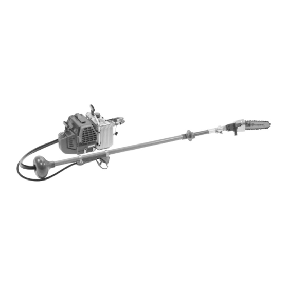
- Page 1 For Husqvarna Parts Call 606-678-9623 or 606-561-4983 Workshop manual 250 PS Nummer XX www.mymowerparts.com...
-
Page 2: Technical Specification
For Husqvarna Parts Call 606-678-9623 or 606-561-4983 Technical specification Engine Cylinder volume Cylinder diameter Stroke Idle speed 2 500 Max. recommended speed 11 000 Hydraulic transmission Hydraulic motor capacity /rev Hydraulic pump capacity /rev Working pressure, high pressure hose Pulse pressure, high pressure hose... -
Page 3: Table Of Contents
For Husqvarna Parts Call 606-678-9623 or 606-561-4983 Husqvarna 250 PS Chapter Page Service data Starter unit Fuel system Throttle lock Ignition system Clutch Cylinder and piston Crankcase and crankshaft Hydraulics www.mymowerparts.com... -
Page 4: Service Data
For Husqvarna Parts Call 606-678-9623 or 606-561-4983 1. Service data Remember..never start the pruning saw if the hydraulic oil ...do not use the pruning saw until it has been tank or hoses/shaft are not fitted. If the hydraulic properly adjusted or repaired. - Page 5 For best results use Husqvarna two-stroke oil, which is specially developed for pruning saws. Mixture ratio: 1:50 (2%). If Husqvarna two-stroke oil is not available you may use another high quality two-stroke oil made for air-cooled engines. Mixture ratio: 1:33 (3%) - 1:25 (4%).
- Page 6 For Husqvarna Parts Call 606-678-9623 or 606-561-4983 Tools 502 50 46-01 Spacer 502 42 45-01 502 50 66-02 Test hose U key 502 42 50-01 502 50 71-01 Tool for pressure Cover plate, relief valve exhaust 502 50 72-01 Cover plate, inlet...
- Page 7 For Husqvarna Parts Call 606-678-9623 or 606-561-4983 Tools 502 50 86-01 3 mm 502 50 87-01 4 mm 502 50 88-01 5 mm Allen screwdriver with ball 502 50 06-01 502 50 91-02 Pliers, ignition cable Touch-up paint, orange 6 mm...
- Page 8 For Husqvarna Parts Call 606-678-9623 or 606-561-4983 Bolt torques 39 Nm 38 Nm 40 Nm Cylinder cover Silencer 27 Nm 28 Nm Air filter, carburettor 29 Nm 42 Nm Fuel tank www.mymowerparts.com...
- Page 9 For Husqvarna Parts Call 606-678-9623 or 606-561-4983 Bolt torques 25 Nm 36 Nm 26 Nm 37 Nm Starter unit 35 Nm Cylinder, piston 33 Nm Crankcase, crankshaft 32 Nm 34 Nm 41 Nm 32 Nm Flywheel, ignition module 22 Nm...
- Page 10 For Husqvarna Parts Call 606-678-9623 or 606-561-4983 Bolt torques 59 Nm Hydraulic oil tank 56 Nm 58 Nm 55 Nm 57 Nm 54 Nm 30 Nm 48 Nm 31 Nm 53 Nm 10 Nm 50 Nm 52 Nm 51 Nm...
- Page 11 For Husqvarna Parts Call 606-678-9623 or 606-561-4983 Bolt torques 5 Nm 3 Nm 7 Nm 2 Nm 4 Nm 8 Nm 12 Nm 15 Nm 16 Nm Throttle handle Shaft, hydraulic hose Sele 46 Nm 21 Nm 45 Nm 17 Nm...
-
Page 12: Starter Unit
For Husqvarna Parts Call 606-678-9623 or 606-561-4983 2. Starter unit WARNING! If handled carelessly the return spring may spring out and cause injury. Always take care when you replace the starter cord or spring. Wear safety goggles! Removal Undo the four fuel tank clamps and move the fuel tank out of the way. - Page 13 For Husqvarna Parts Call 606-678-9623 or 606-561-4983 Thread in a new cord and attach it to the pulley. Wind about 4 turns of the cord around the pulley, anticlockwise. Fit the pulley above the spring cassette so that the end of the return spring engages in the pulley.
-
Page 14: Fuel System
For Husqvarna Parts Call 606-678-9623 or 606-561-4983 3. Fuel system Cleaning the air filter The air filter has two components. A low resistance pre- filter and the air filter itself. Regularly clean any dust or dirt from the air filter to prevent: •... - Page 15 For Husqvarna Parts Call 606-678-9623 or 606-561-4983 Carburettor The carburettor is of the membrane type. It is divided into three units or main functions. 1. Metering unit This includes the fuel jets and control mechanism. 2. Mixture unit This is where fuel and air are mixed in the venturi and includes the choke and throttle flap.
- Page 16 For Husqvarna Parts Call 606-678-9623 or 606-561-4983 Remove the membrane cover and carefully lift off the control membrane. Connect the pressure tester to the fuel hose nipple. Lower the carburettor into a container filled with petrol. Pressure test to 0.4 bar (40 kPa). No leakage is permitted.
- Page 17 For Husqvarna Parts Call 606-678-9623 or 606-561-4983 Remove the screw and lift the cover off the pump membrane Lift off the gasket and pump membrane. Carefully remove the fuel mesh using a needle, for example. Unscrew the jet needles. (H=long, L=short). Clean all components.
- Page 18 For Husqvarna Parts Call 606-678-9623 or 606-561-4983 If the carburettor is very dirty the chamber under the blind plug must also be cleaned. Drill a small hole in the centre of the blind plug and carefully prise it out. Clean the carburettor housing and blow all channels clean using compressed air.
- Page 19 For Husqvarna Parts Call 606-678-9623 or 606-561-4983 Fit the cover. Fit the pump unit components. Replace the fuel mesh if it is damaged. Fit a new pump membrane and new gasket if necessary. Fit the H and L needles. Check the angle of the fuel hose nipple if it was moved during servicing.
- Page 20 For Husqvarna Parts Call 606-678-9623 or 606-561-4983 Check that the spacer is undamaged and that the pulse channel is not blocked. Fit the filter holder and carburettor bolts (with insulating sleeves) to the carburettor. Fit the gaskets and spacer. Insert the spacer through the baffle.
- Page 21 For Husqvarna Parts Call 606-678-9623 or 606-561-4983 Carburettor operation and adjustment WARNING! Never start the pruning saw if the hydraulic oil tank and hoses are not fitted. If the hydraulic oil tank is not fitted the clutch may come loose and cause injury. If the hoses are not fitted the engine cannot be revved up and the hydraulic pump and clutch may be damaged.
- Page 22 For Husqvarna Parts Call 606-678-9623 or 606-561-4983 Fine tuning First adjust the L needle, followed by the T needle, and finally the idle screw T. The recommended engine speeds are as follows: Max. engine speed11,000 rpm Idle speed 2,500 rpm...
-
Page 23: Trouble Shooting Chart
For Husqvarna Parts Call 606-678-9623 or 606-561-4983 Trouble shooting chart Difficulty starting • • • • Fuel drips from carburettor • • No idle • • • • Idles irregularly • • • • Idle setting too rich • •... -
Page 24: Throttle Lock
For Husqvarna Parts Call 606-678-9623 or 606-561-4983 4. Throttle lock Removal Undo the six screws that hold the handle together. Open up the handle. Remove the throttle lock and check the spring underneath it. Assembly Secure the spring under the throttle lock and lay the cable and leads as shown in the diagram. -
Page 25: Ignition System
For Husqvarna Parts Call 606-678-9623 or 606-561-4983 5. Ignition system Checking the spark Remove the spark plug and clean off any carbon deposits. Check the electrode gap. It should be 0.5 mm. If the electrodes are worn you should replace the spark plug. - Page 26 For Husqvarna Parts Call 606-678-9623 or 606-561-4983 Unscrew the piston stop. Fit the key over the flywheel using the two M5 bolts. Centre the key, tighten the M5 bolts and screw in the puller. Remove the flywheel. Assembly Remove the key from the flywheel. Check that the starter lugs move freely, that they are not worn or damaged and that the return springs provide the required tension.
- Page 27 For Husqvarna Parts Call 606-678-9623 or 606-561-4983 Connect the short circuit lead to the ignition module and fit the module on the crankcase without tightening the screws. Place the feeler gauge between the module and the flywheel magnets. Push the module against the flywheel and tighten the screws.
-
Page 28: Clutch
For Husqvarna Parts Call 606-678-9623 or 606-561-4983 6. Clutch WARNING! Never start the pruning saw if the hydraulic oil tank and hoses are not fitted. Otherwise the clutch may come loose and cause injury. Removal Fit the piston plug in the spark plug hole. Use the full thread length! Unscrew the 4 engine adapter bolts. - Page 29 For Husqvarna Parts Call 606-678-9623 or 606-561-4983 Assembly Fit the clutch in place and tighten the nut (clockwise). Fit the engine adapter with the hole on top and the slot at the bottom. www.mymowerparts.com...
-
Page 30: Cylinder And Piston
For Husqvarna Parts Call 606-678-9623 or 606-561-4983 7. Cylinder and piston Removal Remove the cylinder cover. Remove the air filter, carburettor assembly, silencer cover, silencer and spark plug. Undo the cylinder bolts in diagonal sequence and lift off the cylinder. Clean any carbon deposits from the cylin- der. - Page 31 For Husqvarna Parts Call 606-678-9623 or 606-561-4983 Fit the cylinder with the aid of assembly kit 502 50 70-01 making sure that the opening in the piston ring is in line with the guide pin. Do not forget the cylinder base gasket.
- Page 32 For Husqvarna Parts Call 606-678-9623 or 606-561-4983 Silencer It is a legal requirement in some countries that the silencer is fitted with a spark arrester mesh. Check the mesh, clean or replace it if it is damaged. If a spark arrester mesh is not required by law then a silencer without spark arrester mesh should be used.
-
Page 33: Crankcase And Crankshaft
For Husqvarna Parts Call 606-678-9623 or 606-561-4983 8. Crankcase and crankshaft Replacing sealing rings Magnet side Remove the cylinder cover, air filter, starter unit and baffle. Remove the flywheel. (See pages 25-26.) Undo the 3 bolts that hold the housing onto the crankcase. - Page 34 For Husqvarna Parts Call 606-678-9623 or 606-561-4983 Opening the crankcase Remove the ignition system, clutch, cylinder assembly, piston and cylinder base gasket. Undo the seven crankcase bolts, unscrewing them a short distance at a time. Fit tool 502 51 61-01 and separate the two crankcase halves.
- Page 35 For Husqvarna Parts Call 606-678-9623 or 606-561-4983 Check the big end of the piston rod. Replace the crankshaft if there are signs of seizing or discoloration on the sides. The piston rod should not show any noticeable radial play (up and down movement) although sideways play is acceptable.
- Page 36 For Husqvarna Parts Call 606-678-9623 or 606-561-4983 Heat the magnet side of the crankcase. Grease and fit a new crankcase gasket. Place it on the drive side of the crankcase, line up the gasket with the bolts and pull the two crankcase halves together using the fitting tool.
- Page 37 For Husqvarna Parts Call 606-678-9623 or 606-561-4983 Fit the piston (arrow points towards exhaust port) and the cylinder assembly. Use a new cylinder base gasket. Fit the ignition system. Smear the bolts with Loctite. Fit the starter unit. Fit the clutch and engine adapter.
-
Page 38: Hydraulics
For Husqvarna Parts Call 606-678-9623 or 606-561-4983 9. Hydraulics WARNING! Whenever you handle hydraulic Fuel components take care to ensure that no dirt enters the system. Dirt will cause operating problems in the hydraulic system. Recommended hydraulic oil Hydraulic oil such as ISO grade Shell Tellus T32 is recommended if the air temp. - Page 39 For Husqvarna Parts Call 606-678-9623 or 606-561-4983 Use tool no. 502 52 16-01 and tool no. 502 52 13-01 (with square socket) to remove the clutch drum. NOTE! Turn the Allen key clockwise! Undo all 8 bolts and remove the tank adapter.
- Page 40 For Husqvarna Parts Call 606-678-9623 or 606-561-4983 Assembly Fit the rubber sleeve in the opening. Hold the knurled side of the support ring against the rubber sleeve on the inside of the tank and bolt the tank adapter in place. Make sure the locating studs on the adapter are correctly positioned.
- Page 41 For Husqvarna Parts Call 606-678-9623 or 606-561-4983 Screw the clutch drum on by turning it clockwise. Connect the hydraulic oil tank to the engine unit. Hydraulic pump Removal Remove the clutch drum, tank adapter and diffuser. Detach the hydraulic pump and lift it out. Disconnect the hydraulic hose.
- Page 42 For Husqvarna Parts Call 606-678-9623 or 606-561-4983 Heat the pump around the shaft and gently tap the shaft with a copper or lead mallet. If the shaft with its bearing and sealing ring does not come out then apply more heat.
- Page 43 For Husqvarna Parts Call 606-678-9623 or 606-561-4983 Undo the chain drive cog by holding the cog with a polygrip and inserting tool no. 502 52 13-01 (4 mm Allen key) into the shaft of the hydraulic motor. Turn the Allen key clockwise.
- Page 44 For Husqvarna Parts Call 606-678-9623 or 606-561-4983 Separate the shaft tubes so that you can pull one hose at a time through the first tube. Start with the return hose. Remove the shaft clips, if fitted. Pull the hoses through the second tube and third tube, if fitted.
- Page 45 For Husqvarna Parts Call 606-678-9623 or 606-561-4983 Fit the rubber sheath back in place and connect the hoses to the motor. Do not forget the jubilee clamp on the return hose. Bolt the bar plate onto the ball joint mounting, fit the motor to the bar plate and screw on the chain drive cog.
- Page 46 For Husqvarna Parts Call 606-678-9623 or 606-561-4983 Removal Disconnect the hydraulic motor from the bar mounting and hoses. For more information see Hydraulic pump, Removal, pages 41-42. Assembly See Hydraulic pump, Assembly, page 42. Connect the hoses to the motor and bolt the motor onto the bar mounting.
- Page 47 For Husqvarna Parts Call 606-678-9623 or 606-561-4983 www.mymowerparts.com...
Need help?
Do you have a question about the 250 PS and is the answer not in the manual?
Questions and answers