Volvo Penta D4 Operator's Manual
Hide thumbs
Also See for D4:
- Operator's manual (150 pages) ,
- Service and maintenance manual (134 pages) ,
- Operator's manual (124 pages)
Table of Contents
Advertisement
Advertisement
Table of Contents

Related Manuals for Volvo Penta D4


Summary of Contents for Volvo Penta D4
- Page 1 OPERATOR’S MANUAL D4, D6...
-
Page 2: Proposition 65 Warning
This operator‘s manual is available in Denne instruktionsbog kan bestilles English. på dansk. Compelte the form t the end of the operator‘s Bestillingskupon findes i slutningen af instruk- manual to order a copy. tionsbogen. Diese Betriebsanleitung ist auch auf Tämän ohjekirjan voi tilata myös suo- Deutsch erhältlich. - Page 3 Welcome aboard Volvo Penta marine engines are used all over the world. They are used in all possible operating conditions for professional as well as leisure purposes. That’s not surprising. After 100 years as an engine manufacturer the Volvo Penta name has become a symbol of reli- ability, technical innovation, top of the range performance and long service life. We also believe that this is what you demand and expect of your Volvo Penta engine. We would like you to read this operator’s manual thoroughly and consider the advice we give on operation and maintenance before your maiden voyage so that you will be ensured of fulfilling your expectations. Please pay attention to the safety instructions contained in the manual. As owner of a Volvo Penta marine engine, we would also like to welcome you to a worldwide network of dealers and service workshops to assist you with technical advice, service require- ments and replacement parts. Please contact your nearest authorized Volvo Penta dealer for assistance. We also invite you to visit our home page on the Internet at www.volvopenta.com With warm regards AB VOLVO PENTA...
-
Page 4: Table Of Contents
Contents Safety Information .......... 3–7 Maintenance schedule ........63-65 General ..............3 Maintenance ........... 66–96 Boat travel............... 4 Engine, general ............ 66 Maintenance and service ........6 Lubrication system ..........70 Introduction ........... 8–12 Freshwater system ..........73 Running-in ............. 8 Seawater system ..........76 Fuel and oil types .......... 8 Fuel system ............80 Certificated engines .......... 9 Electrical system .......... -
Page 5: Safety Information
Safety Information Read this chapter carefully. It concerns your safety. This section describes how safety information is presented in the operator’s manual and on the engine. It also gives a general account of basic safety precautions to be taken when operating the boat and maintaining the engine. Check that you have the correct operator’s manual before you read on. If this is not the case please con- tact your Volvo Penta dealer. If operations are performed incorrectly it could result in personal injury, or damage to property or the engine. Read the operator’s manual carefully before operating or servicing the engine. If anything is unclear please contact your Volvo Penta dealer for assistance. This symbol is used in the book and on the engine to make you aware of safety information. Always read these safety precautions very carefully. In the operator’s manual warning texts have the following priority: WARNING! If these instructions are not followed there is a danger of personal injury, exten- sive damage to the product or serious mechanical malfunction. IMPORTANT! Used to draw your attention to something that can cause damage, product malfunction or damage to property. -
Page 6: Boat Travel
Safety Information Safety precautions to be taken when operating the boat Your new boat Refueling Read operator’s manuals and other information When refueling there is always a danger of fire and supplied with your new boat. Learn to operate the explosion. Smoking is forbidden and the engine must engine, controls and other equipment safely and cor- be switched off. rectly. Never overfill the tank. Close the fuel tank filler cap If this is your first boat, or is a boat type with which properly. you are not familiar, we recommend that you prac- Only use the fuel recommended in the operator’s tice controlling the boat in peace and quiet. Learn manual. The wrong grade of fuel can cause operat- how the boat behaves at different speeds, weather ing problems or cause the engine to stop. On a diesel conditions and loads before casting off for your “real” engine poor quality fuel can cause the control rod to maiden voyage. seize and the engine to overrev with a resultant risk Remember that the person driving a boat is legally of damage to the engine and personal injury. required to know and follow the current rules regard- ing traffic and safety at sea. Make sure you know the Do not start the engine rules that apply to you and the waters you are sailing Do not start or run the engine with a suspected fuel in by contacting the relevant authorities or organiza-... - Page 7 Safety Information Carbon monoxide poisoning Most modern boats, however, are designed in such When a boat is moving forward, it will cause a cer- tain vacuum to form behind the boat. In unfortunate a way that this problem is very rare. If suction should circumstances, the suction from this vacuum can be arise anyway, do not open hatches or portholes at so great that the exhaust gases from the boat are the fore of the boat. Surprisingly, this will otherwise increase the suction. Try changing speed, trim or load drawn into the cockpit or cabin and cause carbon mo- noxide poisoning. distribution instead. Try taking down/opening or in any other way changing the setup of the cover as well. This problem is most prevalent on high, wide boats Get in touch with your boat dealer for help in obtain- with abrupt stern. In certain conditions, however, this ing the best solution for your boat. suction can be a problem on other boats, e.g. when running with the cover up. Other factors that can in- crease the effect of the suction are wind conditions, load distribution, swells, trim, open hatches and port- holes, etc. Checklist Safety equipment Life jackets for all passengers, communication equipment, emergency rockets, ● approved fire extinguisher, first-aid equipment, life belt, anchor, paddle, torch etc. Replacement parts and tools: impeller, fuel filters, fuses, tape, hose clamps, engine oil, propeller ● and tools for any repairs that might have to be carried out. Get out your charts and go over the planned route. Calculate distance and fuel consumption. Lis- ● ten to the weather reports Make sure that relations or contact persons are informed when planning a longer voyage. Re- ● member to inform them if your plans have changed or been delayed. Tell your passengers and crew where the safety equipment is stored and how to operate it. Make ●...
-
Page 8: Maintenance And Service
Safety Information Safety precautions for maintenance and service operations Preparations Never start a turbocharged engine without installing the air cleaner (ACL). The rotating compressor in the Knowledge Turbocharger unit can cause serious personal injury. The operator’s manual contains instructions on how Foreign objects can also be sucked in and cause me- to carry out general maintenance and service opera- chanical damage to the unit. tions safely and correctly. Read the instructions care- fully before starting work. Fire and explosion Service literature covering more complicated opera- tions is available from your Volvo Penta dealer. Fuel and lubrication oil All fuel, most lubricants and many chemicals are Never carry out any work on the engine if you are inflammable. Read and follow the instructions on the unsure of how it should be done, contact your Volvo packaging. Penta dealer who will be glad to offer assistance. When carrying out work on the fuel system make Stop the engine sure the engine is cold. A fuel spill onto a hot surface Stop the engine before opening or removing engine or electrical components can cause a fire. -
Page 9: Fuel System
Safety Information Hot surfaces and fluids Fuel system There is always a risk of burns when working with Always use protective gloves when tracing leaks. a hot engine. Beware of hot surfaces. For example: Liquids ejected under pressure can penetrate body the exhaust pipe, Turbo unit, oil pan, charge air pipe, tissue and cause serious injury. There is a danger of starter element, hot coolant and hot oil in oil lines and blood poisoning. hoses. Always cover the generator if it is located under the fuel filter. The generator can be damaged by spilled fuel. Carbon monoxide poisoning Only start the engine in a well-ventilated area. If op- erating the engine in an enclosed space, ensure that Electrical system there is proper ventilation in order to remove exhaust gases and crankcase ventilation emissions from the Cutting off power working area. Always stop the engine and break the current using the main switches before working on the electrical system. Isolate shore current to the engine block Chemicals heater, battery charger, or accessories mounted on Most chemicals such as anti-freeze, rustproofing the engine. agent, inhibiting oil, degreasing agent etc. are haz- ardous to health. Read and follow the instructions on Batteries the packaging. -
Page 10: Introduction
Introduction This operator’s manual has been compiled to help you get the most from your Volvo Penta engine. It contains all the information you need in order to operate and maintain your engine safely and correctly. Please read the operator’s manual carefully and learn how to operate the engine, controls and other equipment safely. Always have the operator’s manual available. Keep it in a safe place and do not forget to give it to the new owner if you sell your boat. Care of the environment Fuel and oils We would all like to live in a clean and healthy envi- Only use the fuel and oils recommended in the chap- ter Technical Data. Other grades of fuel and oil can ronment. Somewhere where we can breathe clean cause operating problems, increased fuel consump- air, see healthy trees, have clean water in our lakes and oceans, and are able to enjoy the sunshine wit- tion and, in the long-term, a shorter engine service hout being worried about our health. Unfortunately, life. this cannot be taken for granted nowadays but is so- Always change oil, oil filters and fuel filters at the re- mething we must work together to achieve. commended intervals. As a manufacturer of marine engines, Volvo Penta has a special responsibility, why care of the environment is a core value in our product development. Today, Volvo Service and replacement parts Penta has a broad range of engines where progress has been made in reducing exhaust emissions, fuel Volvo Penta marine engines are designed for high consumption, engine noise, etc. operational reliability and long service life. They are constructed to withstand the marine environment We hope you will take care in preserving these qua- while also affecting it as little as possible. Through lities. Always follow any advice given in the instruc-... -
Page 11: Certificated Engines
AB Volvo Penta’s responsibility for the engine The service of injection pumps and injectors or ● specification being in accordance with the cer- pump settings must always be carried out by an tificated variant. authorized Volvo Penta workshop. Volvo Penta accepts no responsibility or liabil- ity for any damage or costs arising due to the above. Warranty Your new Volvo Penta marine engine is covered by a limited warranty according to the conditions and instructions contained in the Warranty and Service book. Note that AB Volvo Penta’s liability is limited to that contained in the Warranty and Service Book. Read this book as soon as you take delivery of the engine. It contains important information about warranty cards, service and maintenance which you, the owner, must be aware of, check and carry out. Liability covered in the warranty may otherwise be refused by AB Volvo Penta. Contact your Volvo Penta dealer if you have not received a Warranty and Service Book and a customer copy of the warranty card. - Page 12 Other Community Directives applied ......EMC 89/336/EEC Description of engine(s) and essential requirements Engine type ............4 stroke diesel engine with stern drive with integral exhaust Engine model(s) covered by this declaration EC Type certificate number D4-180 ................EXVOLV001 D4-210 ................EXVOLV001 D4-225 ................EXVOLV001 D4-260 ................EXVOLV001 D4-300 ................EXVOLV001 D6-280 ................EXVOLV001 D6-310 .
- Page 13 Declaration of Conformity for Recreational Craft Propulsion Engines with the sound emission requirements of Directive 94/25/EC as amended by 2003/44/EC D4, D6 Engine manufacturer: Body for sound emission assessment AB Volvo Penta International Marine Certification Institute Gropegårdsgatan Rue Abbé Cuypres 3 405 08 Göteborg B-1040 Bruxells Sweden Belgium ID Number:0609 Module used for sound emission assessment ..Aa...
-
Page 14: Identification Numbers
Introduction Identification numbers Always provide the engine and transmission identification numbers when ordering service or replacement com- ponents. The identification numbers are on an information decal located on the front edge of the engine. Note the infor- mation below. Make a copy of the page. Store the information so that it is available in event of the boat being stolen. Engine Product designation (1*) Serial number (2*) Product number (3*) Warranty decal Drive/Reverse gear (Engine/Transom shield/Drive/Reverse gear ) Product designation (4*) Gear ratio (5*) Serial number (6*) Product number (7*) Engine plate Shield (Drive) Product designation (8*) Serial number (9*) Product number (10*) Drive plate Transom shield plate * The numbers refer to the position of the identification numbers on the information decal Reverse gear plate Location of information decal and identification plates: Warranty decal, IMO decal and EPA decal Transom shield plate Drive plate Reverse gear plate Engine plate... -
Page 15: Presentation
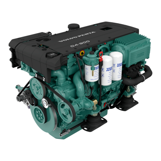
Volvo Penta’s D4 and D6 is developed from the latest design in modern diesel technology. The engine has com- mon rail fuel injection system, double overhead camshafts, 4 valves per cylinder, turbocharger, compressor, and aftercooler. The interaction of these, the large swept volume, and the EVC system results in exceptional diesel performance combined with low emissions. Technical description: Engine block and head Instruments/control — Cylinder block and cylinder head made of cast- — Complete instrumentation including key switch iron and interlocked alarm — Digital Power trim instrument with analog or digital — Combined ladder frame and balance shafts (D4) reading — Ladder frame fitted to engine block (D6) — EVC monitoring panels for single or twin installa- — Double overhead camshafts tions — Oil-cooled pistons with two compression rings and — Electronic remote control for throttle and shift one oil scraper ring — Plug-in connections — Integrated cylinder liners Drive — Replaceable valve seats — Complete with transom shield, and installation... -
Page 16: Engine Monitoring And Evc
Presentation Engine Management and EVC system Helm station Con- trol Unit (HCU)) Helm station Con- trol Unit (HCU) CAN bus Power train Control Unit (PCU) Engine Management System (EMS) Engine Management System To protect the engine at too high coolant or charge air The engines are equipped with common rail system temperatures and boost pressure as well as oil pres- and electronically controlled injectors with an elec- sure the monitoring system reduces the amount of tronic control module. fuel (reduced engine output) until the current values The injectors contain an electro-magnetic valve which normalises. sets the amount of fuel injected and the correct tim- ing. The monitoring system measures the charge air The engine monitoring system also has a diagnostic pressure and temperature, and calculates the avail- system, which helps users and service technicians to able air mass. This determines the maximum amount determine the cause of malfunctions. of fuel that can be injected (smoke limiter function). Users get information about faults by pop-ups that The system also limits the maximum torque available are shown on the EVC system tachometer display. - Page 17 Presentation The EVC system EVC system tachometer The EVC system tachometer is mandatory for boats The Electronic Vessel Control (EVC) system is a so with EVC, unless the optional EVC system display called distributed system. The principle of a distrib- is installed. The tachometer display shows operation uted system is to have many small electonic units, information, information massages and alarms. The called nodes, located on suitable places in the boat. user selects what operation information to display with the control panel. NOTE! Only one operation in- The EVC nodes are the Powertrain Control Unit formation can be displayed at one and the same time. (PCU) and the Helm station Control Unit (HCU). Nodes are located close to the components they The EVC system tachometer and control panel is control. A helm node is located close to the helm. A also used when calibrating EVC functions. powertrain node is mounted in the engine room. Power Trim Each node controls a number of adjacent compo- The function is considerably improved compared nents, for example sensors, controls, instruments and actuators. to non EVC governed Power trim systems. EVC in- troduces a new trim panel with the same design as Each PCU and HCU is programmed for a specific other EVC control panels. If you have a twin engine engine individual. On the PCU and HCU there is a installation the stern drives can be both individually sticker with chassis no. The chassis no. shall corre- and simultaneously controlled. spond to the sticker on the engine.
- Page 18 Presentation Fresh water level Fresh water level can be displayed on the EVC sys- tem tachometer if a (3-180 ohm) fuel level sender is installed in the water tank. The sender is connected to the PCU–engine cable harness. If a fresh water level gauge is used it must be connected to the instrument serial communication bus. Rudder indicator Rudder angle can be displayed on the EVC system tachometer if a (3-180 ohm) rudder indicator is in- stalled to the drive/rudder. The sender is connected to the PCU–engine cable harness. If a rudder instrument is used it must be connected to the instrument serial communication bus. Multisensor (Boat speed, depth and water temp) Boart speed, depth and water temperature canbe dis- played on the EVC system tachometer if a multi sen- sor is installed on the boat. The sensor is connected to the multilink cable. If instruments (speed, depth, water temp.) are used they must be connected to the instrument serial communication bus. Power Trim Assistant The function power trim assistant adjust trim angle automatically according to engine speed (rpm). EVC supports power trim assistant if software for power- trim assistance is installed (order and download from VODIA website). Boat speed Boat speed can be shown on the EVC system ta- chometer, if a multisensor or NMEA 0183/NMEA 2000 compatible component (plotter, GPS, paddle wheel...
-
Page 19: Orientation
Presentation Orientation D4 with drive, starboard 1. Zinc anode 2. Cooling water intake 3. Zinc anode 4. Turbocharger 5. Crankcase ventilation filter 6. Aux Stop 7. Air filter 8. Compressor 9. EDC control module 10. Generator 11. Oil filler cap D4 with drive, port 11. Sea water filter 1 2. Sea water pump 1 3. Fuel filter 14. Oil dipstick... - Page 20 Presentation D4 with reverse gear, starboard 1. Turbocharger 2. Crankcase ventilation filter 3. Aux Stop 4. Air filter 5. EDC control module 6. Generator 7. Oil filler cap D4 with reverse gear, port 8. Sea water pump 9. Fuel filter 10. Oil dipstick (engine) 1 1. Oil bypass filter 12. Oil filter 13. Starter 14. Charge air cooler 15. Oil dipstick (reverse gear)
- Page 21 Presentation D6 with drive, starboard 1. Zinc anode 2. Cooling water intake 3. Zinc anode 4. Turbocharger 5. Crankcase ventilation filter 6. Aux Stop 7. Air filter 8. Compressor 9. EDC control module 10. Generator 11. Oil filler cap 15 16 D6 with drive, port 11. Sea water filter 1 2. Sea water pump 1 3. Fuel filter 14. Oil dipstick 1 5. Oil bypass filter 16. Oil filter...
-
Page 22: Presentation
Presentation D6 with reverse gear, starboard 1. Turbocharger 2. Crankcase ventilation filter 3. Air filter 4. Aux Stop 5. EDC control module 6. Generator 7. Oil filler cap D6 with reverse gear, port 8. Sea water pump 9. Fuel filter 10. Oil dipstick (engine) 1 1. Oil bypass filter 12. Oil filter 13. Starter 14. Charge air cooler 15. Oil dipstick (reverse gear) 16. Expansion tank... -
Page 23: Instrumentation
Instruments This chapter describes the instrument and control panels sold by Volvo Penta for your engine. If you want to supplement the instrumentation, or if your boat is equipped with instruments not described here, or you are not sure about their function, please contact your Volvo Penta dealer. Ignition lock A tab with the key code accompanies the ignition keys, and is used to order extra ignition keys. Do not store the code where it is accessible to unauthorized persons. S = Stop position. 0 = Key can be inserted and removed. I = System voltage on (drive position). II = Not used. III = Start position. IMPORTANT! Read the starting instructions in the “Engine starting” chapter. Start/stop panel The start/stop panel is used to start or stop the engi- ne. The starter key on the main helm station must be in position “I” (driving position) for the engine to start. The engine can only be stopped if the control panel is activated. IMPORTANT! Read the starting instructions in the “Engine starting” chapter. -
Page 24: Instruments
Instruments Instruments 1. EVC system tachometer (with display) Extra optional instruments 2. Voltmeter 3. Oil pressure gauge 4. Temperature gauge 5. Rudder indicator 6. Fuel level gauge 7. Water level gauge 8. Trim instrument... -
Page 25: Alarm Display
Instruments Alarm display (extra optional) The following warning lamps should never light up during operation. On the other hand, the warning lamps light up when the starter key is first turned to the drive position. Check that all lamps function. When the engine has started, all lamps should have gone out. The lamps flash if the diagnostic function has registered malfunction. When the fault has been acknowledged, the lamp gives continuous light. Warning lamps (should never light up during operation). Oil pressure (red indication) If the oil pressure lamp lights up during operation, the oil pressure in the engine is too low. Stop the engine at once. Check the oil level in the engine. Please refer to “Maintenance: Lubrication” to check and top the oil up. Also check that the oil filters are not blocked. Please refer to “Maintenance: Lubrication system” Please refer to the “In case of emergency” chapter, and you will find detailed information about recommen- ded action in the “Diagnostic function” section. WARNING! Continued operation when the oil pressure is too low can cause serious engine da- mage. Water in fuel filter (orange indication) If the lamp lights up, there is too much water in the wa- ter trap in the fuel filters. - Page 26 Instruments Battery (orange indication) The battery lamp lights up if the alternator is not charging. Stop the engine if this lamp lights up during operation. If the lamp lights up, this can be due to a fault in the electrical system or because the alternator drive belt is slack. Check the alternator drive belts. Please refer to “Maintenance: Engine, general”. Also check that there is no poor contact/broken wires. WARNING! Do not continue operation if there is any problem with the alternator drive belts. This could cause serious engine damage. Coolant temperature (red indication) The coolant temperature lamp lights up when the coolant temperature is too high. Stop the engine if this lamp lights up during operation. Check the coolant level. Please refer to “Maintenan- ce: Fresh water system”. Check that the sea water filter is not blocked. Please refer to “Maintenance: Sea water system” Also check the impeller in the sea water pump. Please refer to “Maintenance: Sea water system”. Please refer to the “In case of emergency” chapter, and you will find detailed information about recommended action in the “Diagnostic function” section. WARNING! Do not open the coolant filler cap when the engine is warm, except in emergencies. Steam or hot fluid could spray out.
- Page 27 Instruments Coolant level (orange indication) The coolant lamp lights up when the coolant level is too low. Check coolant level. Please refer to “Maintenan- ce: Fresh water system”. Red warning indication, serious fault If the red warning indication is shown during opera- tion, a serious fault has occured. Please refer to the “In case of emergency” chapter, and you will find detailed information about recom- mended action in the “Diagnostic function” section. Orange alarm indication, fault If the orange alarm indication is shown during opera- tion, a fault has occured. Please refer to the “In case of emergency” chapter, and you will find detailed information about recom- mended action in the “Diagnostic function” section.
-
Page 28: Evc Control Panel
Instruments EVC control panel The control panel is used in combination with the EVC system tachometer. The tachometer display shows oper- ating information and menus that can be navigated from the control panel. Activation button Navigation wheel Used to activate and lock the control panel and the Used to navigate through the menus shown on the helm station. tachometer EVC system display. Navigate through the menus by turning the wheel. Depress the wheel to Indication (red): confirm a selection. Off: Control panel not activated. Lit: Control panel activated. Tachometer display selection (twin installa- tion, port or starboard tachometer) Flashes: Control panel not activated due to the con- trol lever not being in neutral or the system has been Is used to select which of the engines menu systems locked from another control panel. should be navigable from the control panel. The menu is shown on the display of the corresponding engines tachometer. Select port or starboard. Padlock Indication (red/green): The padlock symbol lights if the control panel is locked Off: Not possible to navigate in menu. -
Page 29: Evc System Tachometer
Instruments EVC System Tachometer Introduction Volvo Penta EVC System Tachometer presents rele- vant boat and engine information to the helmsman. In- formation is presented on a display in the tachometer. Information is depending on engine model, number of sensors and type of accessories. Using the instrument Start-up screen This is the start-up screen for the EVC System Ta- chometer. After a few seconds the first item in MAIN MENU will appear. Main menu structure Main menu Navigating the menus Navigate the menus by turning NAVIGATION WHEEL clockwise or counter-clockwise. Views with a POIN- TING HAND-symbol indicates a SUB-MENU. To enter a SUB-MENU, push NAVIGATION WHEEL. Speed (Optional) Boat speed. Requires multisensor or GPS. Water temp (Optional) Water temperature. Requires multisensor. Depth (Optional) Water depth. Requires multisensor. Trip menu (Optional) Trip menu Shows trip information. Requires the following:... - Page 30 Instruments Trip menu (extra optional) In the TRIP MENU the user gets trip information from the EVC System and the user is allowed to select which view that should be presented in the EVC System Tachometers MAIN MENU as trip information. To get trip infor- mation following are required: - Multisensor or NMEA 0183/NMEA 2000 compatible component (plotter, GPS, paddle wheel etc) - Fuel level sender - Trip computer software NOTE! The accuracy of trip information concerning, and based on, remaining fuel volume depends on which method the user has choosen for calibrating the fuel tank. When in TRIP MENU, select view by turning NAVIGATION WHEEL. To select view as favorite, push NAVIGA- TION WHEEL. System returns to MAIN MENU. Push BACK BUTTON to return to MAIN MENU without setting a new favorite. Units are user selectable. See section "Units" Trip menu structure FUEL REMAINING: Fuel remaining (l, Gal). FUEL ECONOMY: Instantaneous fuel rate per dis- tance (l/nm, l/km, l/mile, Gal/nm, Gal/km, Gal/mile). FUEL RATE: Instantaneous fuel rate per hour (l/h, Gal/h). DISTANCE TO EMPTY: Distance to empty based on instantaneous fuel rate, remaining fuel and speed (nm, km, miles). TIME TO EMPTY: Time to empty based on instanta- neous fuel rate and remaining fuel (h). TRIP DISTANCE: Trip distance since last reset (nm, km, miles).
- Page 31 Instruments Gauges menu In GAUGES MENU the user gets information from analogue senders, placed on the engine. If the data is not available the parameter will not be displayed. When in GAUGES MENU, select view by turning NAVIGATION WHEEL. To select view as favorite, push NAVI- GATION WHEEL. System returns to MAIN MENU. Push BACK BUTTON to return to MAIN MENU without setting a new favorite. Gauges menu structure ENGINE HOURS: (h) ENGINE RPM: (RPM) COOLANT TEMP: (°C, °F) ENGINE OIL PRESSURE: (kPa, PSI) EXHAUST TEMP: (°C, °F) TURBO PRESSURE: (kPa, PSI) TRANSMISSION OIL TEMPERATURE: (°C, °F) TRIM ANGLE: (°) RUDDER ANGLE: (°) FUEL LEVEL: (%) FRESH WATER LEVEL: (%) VOLTAGE: (V)
- Page 32 Instruments Settings menu In the SETTINGS MENU the user is allowed to set various options for the EVC system and to calibrate various parameters. IMPORTANT! For all settings and calibration procedures: Activate helm station by pushing the ACTIVA- TION BUTTON. NOTE! For twin installations always perform the settings on the port side system. Port side is the master side. When in SETTINGS MENU, select view by turning NAVIGATION WHEEL. Views with a POINTING HAND-sym- bol indicates a SUB-MENU. To enter a SUB-MENU, push NAVIGATION WHEEL. Push BACK BUTTON to return to MAIN MENU. Settings menu structure PTA (optional): Power trim Assistant (On/Off) DEPTH ALARM: Settings for depth alarm functions. UNITS: Choose which units to display. Set US or met- ric and units for distance, nm, km, miles. PTA CALIBRATION (optional): Calibration of the Power trim Assistant. FUEL TANK CALIBRATION: Calibration of the fuel tank. CHASSIS ID: Shows information about the EVC sys- tem and the VIN (Vehicle Identification Number). SEL LANGUAGE: Select language (10 different) DISPLAY CONTRAST: Adjust the contrast of the dis- play. SPEED FACTOR: Set the calibration factor for the boat´s paddle wheel speed sensor. INFO BEEP: Set info beep sound level for the built-in buzzer in EVC tachometer.
- Page 33 Instruments Depth alarm (extra optional) All depth alarm functions are accessed through this menu. A multisensor needs to be installed. DEPTH ALARM, ON/OFF Depth alarm can be switched ON/OFF. SET DEPTH Adjust the depth alarm value by turning the NAVIGA- TION WHEEL. The value can be adjusted at a resolu- tion of 0.1 m or 1 ft. Once adjustment value is reached, the data is stored by pushing NAVIGATION WHEEL. DEPTH OFFSET The depth sounder can be placed somewhere on the hull that gives another depth than the desired depth. Waterline You can then add or subtract a distance so that the display shows the depth from, for example, the lowest point on the boat, or from the surface. Adjust the depth offset value by turning the NAVIGA- Depth sounder TION WHEEL. The value can be adjusted at a resolu- tion of 0.1 m or 1 ft. Once adjustment value is reached, the data is stored Lowest point by pushing NAVIGATION WHEEL. Depth alarm pop-up The depth alarm pop-up will appear when the depth is less than the depth alarm setpoint. The pop-up shows the actual depth. Acknowledge depth alarm by pushing NAVIGATION WHEEL. The depth alarm pop-up will re-appear every 30 sec- onds until the depth increases and exceeds the depth alarm setpoint.
- Page 34 Instruments Select units and language Choose which units and languages to display. NOTE! Language and unit settings must be performed in all EVC system tachometers. US or METRIC 1. Activate helm station by pushing the ACTIVATION BUTTON. 2. Select SETTINGS from MAIN MENU by turn- ing NAVIGATION WHEEL. Push NAVIGATION WHEEL to enter SETTINGS MENU. 3. Select UNITS and push NAVIGATION WHEEL. 4. Select US OR METRIC and push NAVIGATION WHEEL. 5. Set US or METRIC units by turning NAVIGATION WHEEL and confirm by pushing NAVIGATION WHEEL. DISTANCE 1. Activate helm station by pushing the ACTIVATION BUTTON. 2. Select SETTINGS from MAIN MENU by turn- ing NAVIGATION WHEEL. Push NAVIGATION WHEEL to enter SETTINGS MENU. 3. Select UNITS and push NAVIGATION WHEEL. 4. Select DISTANCE and push NAVIGATION WHEEL. 5. Set distance unit: km, nm or miles and confirm by pushing NAVIGATION WHEEL.
- Page 35 Instruments Power Trim Assistant, PTA (extra optional) The Power trim Assistant adjust trim angle automatically according to engine speed (rpm). It is possible to set five trim angles at five different engine speeds (Idle speed included). PTA CALIBRATION NOTE! For twin installations always perform the PTA CALIBRATION on the port side system. Port side is the master side. 1. Activate helm station by pushing the ACTIVATION BUTTON. 2. Select SETTINGS from MAIN MENU by turn- ing NAVIGATION WHEEL. Push NAVIGATION WHEEL to enter SETTINGS MENU. 3. Select PTA CALIBRATION and push NAVIGATION WHEEL. 4. Select PTA CALIBRATION POSITION (1-5) by turning NAVIGATION WHEEL. Push NAVIGATION WHEEL to enter selected PTA CALIBRATION PO- SITION. 5. Set RPM for PTA CALIBRATION POSITION by turning NAVIGATION WHEEL and confirm by pushing NAVIGATION WHEEL. NOTE! RPM can not be set for PTA CALIBRATION POSITION 1, idling speed. 6. Set TRIM ANGLE for selected PTA CALIBRATION POSITION by turning NAVIGATION WHEEL and confirm by pushing NAVIGATION WHEEL. Use the same procedure for all PTA CALIBRATION POSITIONs (1-5). Push BACK BUTTON to return to SETTINGS MENU.
- Page 36 Instruments Fuel tank calibration There are two possible calibration methods for the fuel tank. One approximative, FULL TANK CALIBRATION, and one more precise, FUEL MULTIPOINT CALIBRATION. A fuel level sender need to be installed. NOTE! If FUEL TANK CALIBRATION is not shown in SETTINGS MENU, please contact your Volvo Penta dealer. FUEL MULTIPOINT CALIBRATION When FUEL MULTIPOINT CALIBRATION is selected, the fuel level sender is calibrated in five equally divid- ed steps; 20% full (pos 1), 40% full (pos 2), 60% full (pos 3), 80% full (pos 4) and 100% full (pos 5) NOTE! To perform multipoint calibration, fuel tank must be LESS than 20% full. If calibration skips POS 1 and goes directly to POS 2, the fuel tank contains to much fuel and the calibration will not be correct. 1. Activate helm station by pushing the ACTIVATION BUTTON. 2. Select SETTINGS from MAIN MENU by turn- ing NAVIGATION WHEEL. Push NAVIGATION WHEEL to enter SETTINGS MENU. 3. Select FUEL TANK CALIBRATION and push NAVIGATION WHEEL. 4. Select FUEL MULTIPOINT CALIBRATION by turning NAVIGATION WHEEL. Push NAVIGATION WHEEL to enter FUEL MULTIPOINT CALIBRA- TION. NOTE! The fuel multipoint calibration procedure dif- fers depending on EVC software release. 5B. If the number after “POS” is not flashing: 5A. If the number after “POS” in the display is flashing: Fill fuel tank with displayed volume (POS 1) and Fill fuel tank with displayed volume (POS 1) and push NAVIGATION WHEEL. Repeat procedure for push NAVIGATION WHEEL. Add fuel (do not reset each POS until the tank is filled.
- Page 37 Instruments FUEL FULL TANK CALIBRATION When FUEL FULL TANK CALIBRATION is selected, the fuel level sender is calibrated in one step. This only gives an approximated value of the fuel level. There- fore all trip data concerning and based on, remaining fuel volume should be recognized as approximated values only. 1. Activate helm station by pushing the ACTIVATION BUTTON. 2. Select SETTINGS from MAIN MENU by turn- ing NAVIGATION WHEEL. Push NAVIGATION WHEEL to enter SETTINGS MENU. 3. Select FUEL TANK CALIBRATION and push NAV- IGATION WHEEL. 4. Select FUEL FULL TANK CALIBRATION by turn- ing NAVIGATION WHEEL. Push NAVIGATION WHEEL to enter FULL TANK CALIBRATION. 4. Fill fuel tank and push NAVIGATION WHEEL. Push BACK BUTTON to return to SETTINGS MENU. Approximated trip data This pop-up will be shown every time after start-up if FUEL FULL TANK CALIBRATION is performed. Fuel alarm pop-up The fuel level alarm pop-up will appear when the fuel level is lower than fuel alarm setpoint. The pop-up shows the percentage of fuel remaining. Acknowledge fuel alarm by pushing NAVIGATION WHEEL.
-
Page 38: Speed Factor
Instruments Speed factor The speed factor for the boat´s paddle wheel speed sensor can be adjusted at a resolution of 1% and is used by the EVC to apply a correction to the output from the speed sensor. Set speed factor Set speed factor while driving the boat. Compare displayed speed with speed data from GPS (or other boat) and adjust the speed factor until they corre- spond. Adjust the speed factor by turning the NAVIGATION WHEEL. Once adjustment value is reached, the data is stored by pushing NAVIGATION WHEEL. Information message Start attempt with gear engaged The engine control lever must always be in neutral be- fore starting. If not, this pop-up will be shown. Approximated trip data This pop-up will be shown every time after start-up if FUEL FULL TANK CALIBRATION is performed. Retrieving faults The EVC system is retrieving faults from its nodes. Monitoring mode (inactive station) An inactive station can show system information. Push MULTIFUNCTION BUTTON on the inactive station. -
Page 39: Evc System Display
Instruments EVC System Display (extra optional) Introduction Volvo Penta EVC system display is an instrument which displays operating information about the engine and allows you to communicate with the engine’s electrical system. Operation information is shown on an LCD display. The driver can select the display mode operative on the display with the aid of the five buttons on the front of the instrument. The four buttons at the furthest left are used to dis- play operating information in different ways. The but- ton at the furthest right is used to adjust the display contrast and to access the so-called configuration menu. Various settings etc. can be done in it. You can also use the configuration menu to reach the display mode SYSTEM INFORMATION (which can also be reached via button 2, please refer to the schedule below). This display mode functions in the same way as the display in the tachometer (EVC System Tacho- meter). Before the display is used, it may be necessary to modify the way that the display shows operating in- formation, to comply with user requirements. You can see the settings that can be changed in the section about the configuration menu. Structure of the display functions Button 2 Button 5 Button 1 Button 3 Button 4 Multi Engine... - Page 40 Instruments Start image This is the starting image that is shown on the display for a brief period after starting. If the unit gives a constant audible warning after star- ting, the self-test has failed. The unit will still work, but may behave in an unexpected manner. Symbols for operating information Engine speed Turbocharge pressure (current) Coolant temperature Induction air temperature Exhaust temperature Engine temperature Fuel pump pressure Voltage Oil pressure Oil pressure, reverse gear Oil temperature, reverse gear Coolant temperature Fuel level Speed Fuel consumption/time Differential pressure, oil filter Display after starting screen Display mode ENGINE (button 1) is always shown af- ter the starting screen when the display is first started up (more information about this display mode can be found below in the instructions). Once the display has been used, it will always show the display mode when it starts up, that was selected when the display was Figure for single engine Figure for twin engine last switched off.
- Page 41 Instruments Set display contrast Press button 5 (furthest right) to set display contrast. Then press the appropriate buttons to adapt the le- vels, then save the settings by pressing EXIT. The display unit has 5 contrast settings. Configuration menu (button 5) (depressed for longer than 3 s) The configuration menu is used to: - access the display mode SYSTEM INFORMA- TION do various settings for the display. reach information and functions for servicing the display. Please refer to the configuration menu structure below and read the following section, which explains each section in the menu. Note! The port engine or both engines must have the ignition switched on when display settings are chan- ged. Configuration menu structure Read more about this display mode System Information on the next page Language (8 available) Settings Bleep...
- Page 42 Instruments Display mode System Information SYSTEM INFORMATION is a display mode that func- tions in the same way as the display in the tachometer (EVC System Tachometer). You navigate round these functions, using the buttons on the free-standing con- trol panel. In display mode SYSTEM INFORMATION there are several functions: - Display of operating information, information mes- SYSTEM INFORMATION display mode for sin- sages and alarm (note! The display is adapted to gle engine installations suit the size of the panel in the tachometer). - Settings for displaying operating information in this display mode. - All calibrations. Detailed instructions for the functions in display mode SYSTEM INFORMATION are found in the section about the tachometer in this owner’s manual . Information message and alarm The display automatically switches to display mode SYSTEM INFORMATION display mode for SYSTEM INFORMATION when the electrical sys- twin engine installations tem needs to show information messages or alarms. Instructions about how information messages and alarms should be handled are found in the section about the tachometer and in the section ”In case of emergency” in this owner’s manual. Control panel Alarm example Settings Menu SETTINGS is used to do various settings for...
- Page 43 Instruments - Display: This is where you set the measurement intervals of the speedometers and tachometers. Rpm engine: [2500 rpm: 9000 r/min] in stages of 500 rpm - Speed: Change speed display (on/off) - Speed: [10 KNOT: 100 KNOT] in states of 10 (in the appropriate speed intervals) - Graph interval: 2 MIN,10 MIN, 30 MIN, 60 MIN, 2 H, 4 H, 8 H - Units: (This menu is only displayed if LOCAL has been selected in menu SETTINGS). This is where you select the measurement units to be used to display operating information. (GLOBAL is pre-set, which means that the units of measurement are pre-set, but they can be changed if LOCAL is se- lected in menu UNITS). - Speed: KNOT, MPH, KM/H - The distance is adjusted to suit the speed unit: NM, MILE, KM - Oil or Turbo pressure: kPa, PSI - Volume: LITER, GAL, Imperial GAL - Fuel consumption / time: is adjusted to suit the volume unit: L/H, GAL/H, IGAL/H - Temperature: °C (CELSIUS), °F (Fahrenheit) System Menu SYSTEM is intended to provide the necessary functions and information for service technicians. - Demo: Switches between demo mode ON/OFF The unit is in normal operation mode when Demo is OFF.
- Page 44 Instruments Display mode Engine (Button 1) This display mode shows the engine speed and boat speed in the form of standard instruments, together with a trip computer and fuel level gauge. The fuel le- vel gauge is displayed if there is a tank sender instal- led. Note! Trip information is only displayed if following are installed: - Multisensor or NMEA 0183/NMEA 2000 compa- Figure for single engine installation tible component (plotter, GPS, paddle wheel etc) - Fuel level sender Software for trip computer (order and download from VODIA website) The trip computer shows various types of information if you repeatedly press the button ENGINE (ENGINE) (button 1). Please refer to the trip computer menu be- low. Note! Only metric values are displayed, but other units can be displayed if they have been chosen in the Figure for twin engine installation configuration menu. The scale values for maximum engine speed and maximum speed can be set in the configuration menu. If information about boat speed is not available, the display shows coolant temperature instead. Menu, trip computer Button 1 Changes display each time the button is pressed Fuel consumption/time (L/hr) Fuel consumption (L/N.M.) -...
- Page 45 Instruments Display mode Multi (button 2) This display mode shows operating information in four different windows (see below). The user can choose the operating information to be displayed in each win- dow. The information can be displayed as figures or as standard instruments. Display indication shifts bet- Example of display in several windows for ween the two modes when you press button 2 repea- single engine installation tedly. If an item of operating information is not available, the unit displays ”—” and the analogue gauge needle is not shown. From this display mode MULTI , you can also reach display mode that functions in the same way as the smaller display in the tachometer. Read more about this display mode SYSTEM INFORMATION in the configuration menu section. Example of display in several windows for twin engine installation Set the appearance of the display mode Multi Display mode MULTI has a mode to set the operating information to be displayed in each window. The setting mode is reached by pressing button 5 (fur- thest right), when you are in the display mode MULTI. Please refer to the illustrations below. Figure for single engine Figure for twin engine Note! The type of operating information available installation...
- Page 46 Instruments Display mode Trip (button 3) This display mode shows: - Fuel used after last zeroing - Instantaneous fuel consumption (amount of fuel used per hour) (If speed information is available, in- stantaneous fuel consumption can also be calcula- ted in relation to distance.) - Operation time after last zeroing - Total operating time (can not be zeroed) Figure for single engine installation If you want to zero the trip values (trip fuel consump- tion and trip operating time), keep button 3 depres- sed for 1 second. The unit beeps and the values are zeroed. Note! When the display is set for a twin engine installation, the information displayed for each engine will be the sum of the values from both engines, apart from operating time. Operation times for twin engines are shown separately. The size of the operating hours figures shown on the Figure for twin engine installation display is reduced if the number does not fit in the window. Display mode Graph (button 4) In this display mode, operating information is display- ed in the form of a histograph. Press button 4 repea- tedly to show different operating information.
-
Page 47: Controls
Controls This chapter describes the instrument panels sold by Volvo Penta for your engine. If your boat is equipped with controls which are not described here and you feel uncertain about the function, please contact the dealer you purchased the boat from. Single lever control. Electronic Operation Both the shift function and engine speed control are con- trolled using the single lever control. N = Neutral position (reverse gear/stern drive is disenga- ged and the engine runs at idle speed). F = Reverse gear/stern drive engaged for movement ahead. R = Reverse gear/stern drive engaged for movement as- tern. T = Adjustment of engine speed. NOTE! The engine can only be started if the Control lever is in the neutral position. Disengaging the shift function The shift function can be disengaged so that the control lever only affects the engine speed. 1. Move the lever to the neutral position (N) 2. Press the neutral button (N) in and hold it down while moving the control lever forward to the shift position (F). 3. Release the neutral button. The green indicator begins to flash to acknowledge that the shift function is disen- gaged. The lever now only controls engine speed. When the lever is moved back to the neutral position it will automatically re-engage. This is confirmed by the green indication which gives constant light. WARNING! Take care not to engage the reverse gear/stern drive unintentionally. -
Page 48: Friction Brake
Controls Friction brake The control has a friction brake which can be adjusted as necessary to provide lighter or heavier lever action. Adjusting the friction brake: 1. Stop the engine. 2. Mover the control lever forwards so that the groove in the hub of the control lever is accessible. 3. Position a screwdriver in the groove and remove the plug. 4. Adjust the friction brake (8 mm wrench): Clockwise = heavier lever action Counter clockwise = lighter lever action. 5. Reinstall the plug. Side mounted control lever. Electronic Operation Both the shift function and engine speed control are con- trolled using the control lever. N = Neutral position (stern drive is disengaged and the engine runs at idle speed). F = Stern drive engaged for movement ahead. R = Stern drive engaged for movement astern. T = Adjustment of engine speed. NOTE! The engine can only be started if the Control le- ver is in the neutral position. - Page 49 Controls Two lever control. Mechanical Operation The two lever control has separate levers for shifting (1) and speed control (2). The control has a neutral position switch that only allows the engine to be started with the reverse gear in neutral. Black lever (1): N = Neutral position. Reverse gear is disengaged. F = Reverse gear engaged for movement ahead. R = Reverse gear engaged for movement astern. Red lever (2): Engine speed control. Friction brake The control has an adjustable friction brake for speed con- trol. Adjust the friction brake by turning the screw (control A) or lever (control B). Turn clockwise (+) for heavier lever movement or anti- clockwise (–) for lighter lever movement.
-
Page 50: Starting The Engine
Starting the engine Make it a habit to give the engine and engine bay a visual check before starting. This will help you to discover quickly if anything abnormal has happened, or is about to happen. Also check that instruments and warning dis- plays show normal values after you have started the engine. To minimize starting smoke in cold starting, we recommend that a heater should be installed to warm the engine bay at temperatures below +5°C. WARNING! Never use start spray or similar products as a starting aid. Explosion risk! Before starting Open the fuel tap ● Open the sea cock (reverse gear) ● Do the tasks under the “Daily before first start” ● heading in the maintenance schedule. Turn the main switches on. ● IMPORTANT! Never disconnect the current with the main switches when the engine is running. This can damage the alternator. Start the engine bay fan, if one is installed, and let ● it run for at least four minutes. Check that the amount of fuel aboard is enough ● for your planned voyage. Check the oil level. ● Lower the drive(s) if raised. ● General information about starting The engine control lever must always be in neutral before starting. The engine management system en- sures that the engine receives the correct amount of fuel - even when the engine is cold. -
Page 51: Starting Method
Starting the engine Starting method Put the reverse gear/stern drive in neutral Put the reverse gear in neutral by moving the control lever(s) to neutral at all control positions. Two lever control: Also check that the engine speed lever is in the idling position. Turn the ignition on Turn the starter key to position I to switch the ignition Check LEDs Each time the ignition is turned on, all LEDs are illumi- nated on the main control panel. Check that all LEDs function. If the boat has more than one control panel, the LEDs on the other panel(s) are not checked until the control panel(s) is(are) activated. Check the tachometer display If a fault is registered it will be shown in the tachome- ter display. Lock the system. If the boat has more than one control panel, the sys- tem can be locked, so that the engine can only be controlled from the activated control board. Press the activation button for a second to lock the system. The... -
Page 52: Start The Engine
Starting the engine Start the engine Start using the ignition switch Turn the key to position III. Release the key and let it key spring back to position I as soon as the engine has started. Stop cranking if the engine does not start with in 20 sek. Starting with the starter button Press the starter button. Release the button as soon as the engine has started. Please note that if you start from an alternative control station, the starter key at the main control station must be in position I. Stop cranking if the engine does not start with in 20 sek. Overheating protection If the starter motor is engaged for its maximum activa- tion time (30 seconds), the starter motor circuit is cut automatically to protect the starter motor from over- heating. Leave the starter motor to cool for at least five minutes (if possible) before making a new start attempt. Read the instruments and warm the engine up Allow the engine to idle for the first ten seconds, and check that instruments and displays show normal val- ues. Check that no alarms are displayed and that no... -
Page 53: Operation
Operation Learn to handle the engine, controls and other equipment in a safe and correct manner before you cast off on your maiden voyage. Remember to avoid sudden or surprising rudder movements and gear shifting. There is a risk that passengers could fall over or overboard. WARNING! A rotating propeller can cause severe injury. Check that there is nobody in the water before you engage forward / aft drive. Never drive close to bathers or in areas where you could reasonably expect that people could be in the water. Reading the instruments Read all instruments directly after starting, and then regu- larly during your voyage. EVC system tachometer Shows user selected boat and engine information. Oil pressure The oil pressure gauge (analouge or in tachometer) should normally indicate between 3-5 bar. It will indicate a somewhat lower value when idling. Coolant temperature The temperature gauge (analouge or in tachometer) should normally indicate between 75– 95°C (167-203°F) during normal operation. Charging The voltmeter (analouge or in tachometer) should normal- ly indicate about 14V. Acknowledging alarms and messages There are several types of alarms and messages that can appear as a pop-up in the tachometer/display. NOTE! Some alarms for fault are also accompanied by a buzzer. First silence the buzzer by pushing the NAVI- GATION WHEEL on the control panel. 1. Read the alarm/message pop-up. -
Page 54: Cruising Speed
Operation Alarm If a fault occurs, the audible warning will sound and the relevant warning lamp on the optional alarm display will start to flash and the tachometer display will show a alarm pop-up. 1. Reduce engine speed to idling. 2. Acknowledged the larm by pressing the navigation wheel on the control panel once. When the fault has been acknowledged, the lamp con- cerned gives constant light and the audible warning will become silent. Please refer to the chapters “In case of emergency” and "Fault register" and you will find detailed information about recommended action. The fault will also be stored in the form of a fault code for as long as the malfunction remains. It is possible to read the fault code during a subsequent service. Cruising speed Avoid operation at full throttle, for best fuel economy. We recommend a cruising speed which is at least 10% below the maximum engine speed at full speed (full throttle). The maximum engine speed will vary due to propeller choice, load and sea conditions, but it should be in the full throttle range. Full throttle range: D4 ............3400–3600 rpm D6 ............3400–3600 rpm If the engine does not reach the full throttle range, this could be caused by a number of factors which are noted in the “Fault tracing” chapter. If the engine speed exceeds the full throttle range, select a coarser pitch propeller. Ask your Volvo Penta dealer for advice. -
Page 55: Changing Helm Station
Operation Changing the helm station The first time you change control panel after starting the EVC system, a bulb check is done automatically. All LEDs and bulbs light up for 2 seconds. 1. Check that the control lever(s) is (are) in neutral on both the control panel you leave and on the new con- trol panel. 2. Check that the EVC system is not locked. 3. Press the activation button (1) for at least one second. When the button is released, the indication lights up to confirm that the control position is activated. 4. Press the activation button (1) for a further second to lock the EVC system. The padlock sign lights up in confirmation. Unlock the system by pressing the ac- tivation button for one second. This can only be done from an activated control panel. Changing helm station while cruising (optional) This function must be enabled to permit the control panel to be changed during operation. The function can only be enabled by authorized Volvo Penta personnel. Please contact your Volvo Penta dealer. 1. Press the activation button (1) to unlock the system. The padlock sign goes out on all control panels to in- dicate that it is possible to change control panel. 2. The control lever on the alternative control panel must be in neutral before it is possible to change control pa- nel. 3. Press the activation button (1) on the alternative con- trol panel. The activation button indication flashes on the alternative control panel, and on the main control panel it gives constant light. -
Page 56: Operation
Operation Operation Shifting between forward and reverse should be done at idling. Shifting at higher engine speeds can be uncomfor- table for passengers and cause unnecessary stress on the stern drive/reverse gear, or cause the engine to stop. If you attempt to shift gear at an excessive engine speed, a safety function cuts in automatically, and delays shifting until engine speed has fallen to 1500 rpm. Always do a forwards/revers operation as follows: 1. Reduce engine speed to idle and let the boat more or less lose way. WARNING! Never shift to reverse when the boat is planing. 2. Move the control lever to neutral with a rapid, distinct movement. Make a brief pause. NOTE! A beep will sound to indicate that the control lever is in neutral. 3. Then move the control lever to reverse with a rapid, distinct movement and increase engine speed. IMPORTANT! If the boat has twin engines, it is important that both should be running during re- verse maneuvers, to avoid the risk of water entry (via the exhaust pipe) into the stationary engine. Power Trim Your Volvo Penta drive is equipped with a hydraulic trim system, with which you can change the angle of the drive in relation to the transom. This will affect the running po- sition of the boat and make it possible to optimize boat handling in various conditions. Power trim is operated from the control position using the panels, controls and instruments. NOTE! The engine can not be started with the drive in the “Tilt range”. - Page 57 Operation Operating with the drive in the Trim range The Trim range is used to achieve maximum comfort un- der normal operation at all speeds from start to maximum speed. Since every boat has its own unique characteristics and will be effected in different ways by the factors involved, only general advice is given here on how to get the best trimming angle for your boat. It can generally be said that when the boat feels well-balanced, easy to steer and pleasant to operate, then that is the optimal trim angle for the boat. To familiarize yourself with the Power trim, make test runs at slower speeds and at various trim positions to see the effect ot trimming. Note the time it takes for the boat plane. Watch the tachometer and speedometer readings and the ride action of the boat. When starting Trim the drive in. The bow will be pressed down and the boat accelerates faster. This gives improved running and steering characteristics at speeds below the planing threshold. Operating in “Bow-down” Position The “bow-down” position is normally used for acceleration onto plane, operating at slow planing speeds, and run- ning against a choppy wave condition. In the fully “bow- down” position the boat may tend to selfsteer. You may have to compensate with the steering wheel to keep the boat in a straight-ahead path. In this position the boat’s bow will tend to go deeper into the water. If the boat is operated at high speed and/or against high waves, the bow of the boat will plow into the water. The boat may...
- Page 58 Operation Operating in “Bow-up” Position The “bow-up” position is normally used for cruising, run- ning with a choppy wave condition, or running at full speed. In a full “bow-up” position the boat may tend to self-steer. You may have to compensate with the steering wheel to keep the boat in a straight-ahead path. In this position the boat’s bow will tend to raise clear of the wa- ter. Excessive “bow-up” trim will cause propeller ventila- tion resulting in propeller slippage. Engine RPM will also increase, but boat speed will not increase and may even drop. IMPORTANT! Use caution when operating in rough water or crossing another boat’s wake. Excessive “bow-up” trim may result in the boat’s bow rising ra- pidly and possibly throwing the boat’s occupants into the water. For maximum fuel economy Operate engine at a steady throttle opening. Trim the drive out/in slightly. The boat is most easily propelled and speed will increase in the position that gives the highest engine speed. The throttle opening can then be slightly reduced to retain the original speed. In choppy seas or running against a heavy sea Trim drive so the bows drop. This will provide more com- fortable running. See section "Operating in Bow-down Position"...
- Page 59 Operation Power Trim Control Panel This control panel is used for both single and twin engine installations. The current position of the drive is shown on the trim instrument, refer to the ”Trim instru- ment” chapter. For twin engine installations, the control panel can be used to make individual or simultaneous adjustments to the drives. By trimming out the drive away from the transom, the height of the bow will be “raised” in relation to the ho- rizontal axis and trimming in the drive will “lower” the bow of the boat. Trimming out the drive Press in button 1 on the control panel to raise the bow of the boat (drive trimmed out). In twin engine installations, both drives can be opera- ted simultaneously by pressing button 1. The drives can be operated separately by pressing button 2 on the control panel for the port drive and button 3 for the starboard drive. Trimming in the drive Press in button 4 on the control panel to lower the bow of the boat (drive trimmed in). In twin engine installations, both drives can be opera- ted simultaneously by pressing button 4. The drives can be operated separately by pressing button 5 on the control panel for the port drive and button 6 for the starboard drive. Emergency trimming If a fault occurs which prevents the drive from being trimmed, it is possible to perform an emergency trim- ming. Please refer to "In case of emergency: Emer-...
-
Page 60: Power Trim Assistant
Operation Tilt range Tilt range is used to lift the drive to maximum height but not when the engine is running. The range is used e.g. for trailing. Power trim has an automatic stop that cuts the power when its end limit has been reached. The stop is reset automatically when activa- ting down trimming. NOTE! The engine can not be started with the drive in the “Tilt range”. Digital trim instrument The display window will show TRIM while the drive angle* is between -5° and +6° (Trim range). The display window will show BEACH while the drive angle* is between +6° and +30° (Beach range). LED (1) lights orange. While the drive angle* is over +30° (Tilt range), the LED (2) will light red. No text in display window. *The number corresponds to the drive angle in relation to the ho- rizontal (stationary boat). The lowest value shows that the drive is at max trim in and the highest value that the drive is raised to max. Observe that the lowest value can vary from boat to boat depending on the angle of the transom. Analogue trim instrument This instrument shows the current position of the dri- ve. Beach range is marked with an orange zone and lift range with a red zone. 1. Trim range. 2. Beach range (orange). -
Page 61: Volvo Penta Lowspeed
Operation Volvo Penta Lowspeed (extra optional) The Volvo Penta Lowspeed function is only available for engines with hydralic reverse gear. For boats with powerful engines, where the boat speed at idle is too high, Volvo Penta Lowspeed is used to reduce boat speed by reducing propeller rpm - compared to normal at engine idle speed. N = Neutral idling (reverse gear disengaged, engine runs at idle speed) F = Forward idling (reverse gear engaged for move- ment ahead, engine runs at idle speed), maximum slip in reverse gear. R = Reverse idling (reverse gear engaged for move- ment astern, engine runs at idle speed), maximum slip in reverse gear. A = Lowspeed active. Propeller rpm is increased with increase of throttle, engine rpm is not affected. B = Lowspeed deactivated. Propeller rpm is increased with engine rpm, engine rpm will increase with Pop-up when Lowspeed is throttle. engaged. It is possible to ack- nowledge pop-up by pushing Engaging Lowspeed NAVIGATION WHEEL. 1. Move the lever to neutral position. 2. Press the neutral button (N) to activate Lowspeed. When Lowspeed is engaged a pop-up (A) is shown on the tachometer display. It is possible to acknowledge pop-up by pushing NAVIGATION Pop-up when initializing WHEEL. -
Page 62: Running Aground
Operation Running aground The automatic Kick-up function releases the drive if it grounds or hits an object in the water. If the function has been tripped and the drive released it must be trimmed back to the original position using the control buttons. IMPORTANT! The Kick-up function only protects the drive when running ahead (forwards). There is no protection for the drive while running astern (backward). Check after running aground that the drive or propel- ler are not damaged or if there are vibrations from the drive. If this is the case then the boat (if possible) should be run to harbor at reduced speed and taken out of the water. Take the boat out of the water. Check the oil level in the drive. If it is colored gray then water has entered the drive. If this is the case or if other damage has occurred to the drive it must be inspected at an autho- rized Volvo Penta workshop. If only the propeller has been damaged it must be replaced. Launch the boat and test drive. If there are still vibrations it must be in- spected by an authorized Volvo Penta workshop. IMPORTANT! To prevent galvanic corrosion any damage to the paintwork on the drive and propel- ler must be repaired before launching the boat: See section “Laying up/Launching”. Control of parallel strut WARNING! If the parallel strut shows signs of damage, run at reduced speed to harbor. The parallel strut is a vital safety component, damage may affect steering characteristics. In the worst case steering could be lost altogether. Never align or weld a damaged parallel strut. Please contact your nearest authorized Volvo Penta workshop for assistance. -
Page 63: Stopping The Engine
Stopping the engine The engine should be run for a few minutes at idle (in neutral) before turning it off. This will avoid boiling and even out the temperature. This is especially important if the engine has been operated at high engine speeds and loads. Stopping Turn the key to stop position “S”. Keep the key turned until the engine stops. The key will automatically return to the “0” position when it is released and can then be removed. IMPORTANT! Never switch off the main switches while the engine is running. This could damage the alternator. IMPORTANT! Never switch off the main switches be- fore the starter key is turned off (is in "0" position or removed). This could damage the electrical system. Auxiliary stop If the engine cannot be stopped in a normal procedure, it is possible to stop the engine via auxiliary stop mounted on the side of the engine. After stopping the engine Close the fuel cock and sea cock (reverse gear) for the ● cooling water intake. IMPORTANT! Do not forget to open the cocks be- fore the engine is started again. Inspect the engine and engine compartment for any ● leaks. Boats with drives: The drive must be trimmed in to its ● maximum to protect the trim cylinders untreated sur- faces from fouling. IMPORTANT! If there is a risk that the drive can run aground, it must instead be trimmed out to its maxi- mum lift position. -
Page 64: Cold Weather Precautions
Stopping the engine Cold weather precautions To prevent freezing damage, the seawater system must be drained and the freshwater system coolant must have sufficient antifreeze protection. Refer to the cooling system section in chapter “Maintenance”. IMPORTANT! A poorly charged battery may burst as a result of freezing. Transporting on a trailer Before pulling boats with a drive on to a trailer, trim the drive out to “Lift range” (maximum lift). An automatic stop will cut off the current to the hydraulic pump when the drive has reached its max. lift point. The stop is automati- cally reset when trimming down. NOTE! Check local legis- lation for transporting boats on trailers, there are differenc- es between different countries’ trailer laws. It is possible to trim the drive without starting the engine. IMPORTANT! The engine must not be run with the drive in the “Lift” range. Before transporting the boat by trailer always secure the drive in the lift position with a Trailer Kit (accessory) or similar, so that it can- not drop down. IMPORTANT! Boats with reverse gear: Drain water out the exhaust system to prevent water entering the engine when transporting the boat by trailer. Laying up on land/Launching IMPORTANT! If the boat (engine) submerges sig- nificantly below the static waterline (A) when it is laid up or launched there is a risk of water entering the engine through the exhaust system. Where boats are kept laid up on land when not in use, there is a lower level of galvanic corrosion protection due to oxidation on the sacrificial anodes. Before launching the boat the sacrificial anodes on the drive and shield must be cleaned with emery paper to remove any oxidation. -
Page 65: Maintenance Schedule
Maintenance schedule General information Your Volvo Penta engine and its equipment are designed for high reliability and long life. They are built to withstand a marine environment, but also to have the smallest possible environmental impact. If given preventive maintenance, according to the maintenance schedule, and if Volvo Penta original spares are used, these quali- ties are retained and unnecessary malfunctions can be avoided. Warranty inspection During the first period of operation, the specified warranty inspection “First service inspection” must be done by an authorised Volvo Penta workshop. Instructions about when and where this should be done are found in the Warranty and service book. Extended Protection Volvo Penta offers an Extended Protection for your marine diesel engine, including transmission, if used for pleasure use only. To be valid a Extended Protection service has to be performed at the owners cost and ex- pense by an authorized Volvo Penta distributor, dealer or workshop before the expiry of the 12 months Warranty Period. Further directions can be found in the Warranty and Service Book. MAINTENANCE SCHEDULE WARNING! Before you do any maintenance work, read the “Maintenance” chapter carefully. This contains advice on doing the work in a safe and correct manner. IMPORTANT! Maintenance points marked must be done by an authorised Volvo Penta workshop. Daily, before first start: ● Engine and engine room. General inspection..........page 66 ● Engine oil. Check level . - Page 66 Maintenance schedule Every 50-200 hours / at least once a year, included in extended protection: ● Engine oil. Change ..................page 71 ● Oil filter. Change ..................page 72 ● Outboard drive. Check/Adjust drive alignment ..........page 95 Every 200 hours / at least once a year, included in extended protection: ● Crankcase ventilation filter. Change .............. page 67 ● Air filter. Change ....................
- Page 67 Maintenance schedule Every 1200 hours / at least every 5 years: ● Drive belts. Change ..................page 68 Drive belt, compressor. Change ..............not shown ● Compressor. Change oil ................page 69 Heat exchanger. Inspect/Clean ..............not shown Intercooler. Inspect/Clean ................not shown Control cables and seals. Change ..............not shown Inspect exhaust hose and cooling water hoses. ........not shown – Check hoses/pipes, unions and hose clamps Safety and function check ................not shown – In a safety and function check, the outboard drive is disassembled to check for wear and damage. Any faults are rectified. If necessary, the complete drive is changed. Every 1500 hours (commercial use): Outboard drive. Change gears, bearings, all bushings and sealing rings ..............not shown Outboard drive. Rebuild or change U-joint ..........not shown Outboard drive. Check propellershaft wear and strightness. Change as required .
-
Page 68: Maintenance
Maintenance This chapter describes how to carry out the above maintenance. Read the instructions carefully before starting work. Maintenance intervals are contained in the chapter above: Maintenance schedule WARNING! Read the safety precautions for maintenance and service in the chapter: Safety Information, before starting work. WARNING! Unless otherwise specified all maintenance and service must be carried out with the engine stopped. Stop the engine before opening or removing engine hatches. Immobilize the engine by removing the ignition key, turning off the power supply with the main switch. Engine, general General inspection Make a habit of “visually” inspecting the engine and engine room before starting the engine and after stopping when the engine has been turned off. This will help you to quickly detect abnormalities that have occurred or are about to occur. Look especially carefully for oil, fuel and coolant leaks, loose bolts, worn or slack drive belts, loose connections, damaged hoses and electric cables. This inspection takes only a few minutes but can prevent serious operating disturbances and costly repairs. WARNING! Accumulations of fuel, oil and grease on the engine or in the engine room is a fire hazard and must be removed immediately they are detected. IMPORTANT! If an oil, fuel or coolant leak is de- tected, the cause must be investigated and the fault rectified before the engine is started. IMPORTANT! Never point high-pressure water jets directly at seals, rubber hoses or electrical components. Never use the high-pressure func- tion when washing the engine. - Page 69 Maintenance. Engine general Changing air filter Remove the air filter cover. Remove the old air filter. Clean the air filter cover/housing if necessary. Take care not to allow impurities to enter the engine. Fit the new air filter and the air filter cover. Changing crankcase ventilation filter Unscrew the lid and remove the old filter. Clean the filter cover/housing if necessary. Take care not to al- low impurities to enter the engine. Fit the new filter.
- Page 70 Maintenance: Engine general Checking exhaust line The exhaust line of drive installations must be in- spected every year with respect to corrosion between the hose (1) and the pipe (2). WARNING! Risk of water entering. The exhaust line must be inspected while the boat is on land. In case of serious corrosion damage, the pipe must be repaired or replaced with a new one. To check: Undo the clamps (3) and (4) holding the hose (1). Detach the hose. Check the contact surface (5). In case of serious corrosion damage, the pipe must be repaired or replaced with a new one. Checking drive belts WARNING! Stop the engine before commen- cing maintenance work. General Check belt tension and condition regularly. If the belt is too taut it can damage bearings and if it is too loose it may slip. Therefore, check the belt tension regularly. Check and adjust after operation when the belt is warm. IMPORTANT ! Always change a belt that ap- pears worn or is cracked (belts working in pairs must be replaced together).
- Page 71 Maintenance. Engine general Compressor. Checking oil Checking and topping up Unscrew and remove the dipstick. Wipe off oil. Screw the dipstick down fully and then remove it again. Check that the level oil is between the markings. If the dipstick is not screwed down fully the oil level will be slightly above the MIN marking if the oil level is cor- rect. Ensure therefore that the dipstick is fully screwed in to read off the oil level correctly. Top up the oil as required (use the dip stick tube to fill). For oil quality and capacity: See the “Technical Data” chapter. IMPORTANT! The oil level should always be within the MAX and MIN range marked on the dipstick. Oil change Run engine to normal operating temperature. Remove the oil dipstick. Remove the plug (1) and let the oil run out. Reinstall the plug and fill with oil to correct level as above.
-
Page 72: Lubrication System
12 months. If you want longer oil change intervals, the condition of the oil must be checked by the oil manufacturers through regular oil testing. Oil change volume Please refer to the “Technical Data” chapter. Checking and topping up the oil level NOTE! Check the oil level every day before the en- gine is started for the first time. IMPORTANT! Do not check the oil level directly after the engine is shut down. The oil in the en- gine needs time run down to the oil pan before a correct oil level check can be performed. Wait 15 minutes if the engine has been run up to normal operating temperatures. Wait one hour if the engine only has been run at idle. IMPORTANT! The oil level should always be be- tween the MAX and MIN marks on the dipstick. Higher or lower oil level than permitted could lead to engine damage. Topping up is done via the filling hole on the top of the engine. Top up oil slowly. Wait 5 minutes before check- ing the oil level again since the oil needs time to run down to the oil pan. Then check the level again. Use only recommended grades of oil: Please refer to the “Technical Data” chapter. NOTE! The volume between MAX and MIN is apporx. 1.5 liter (0.4 US gals) for D4 and 3.5 liter ( 0.9 US gals) for D6. -
Page 73: Changing Engine Oil
Maintenance. Lubrication system Changing engine oil Always observe the recommended oil change interval. IMPORTANT! Only use a recommended grade of oil. Please refer to the “Technical Data” chapter. IMPORTANT! The oil level should always be between the MAX and MIN marks on the dipstick. Higher or lower oil level than permitted could lead to engine damage. 1. Start the engine (this makes it easier to suck the oil up from the sump). Let the engine run till opera- tion temperature is reached (temperature gauge indicate a value between 75– 95°C (167-203°F)). Then stop the engine. WARNING! Hot oil and hot surfaces can cause burns. 2. Connect the oil bilge pump to the drain pipe. Pump up the oil. 3. Change the oil filter and bypass filter at each oil change (please refer to chapter “Changing oil filter and bypass filter”). 4. Fill up with new oil through the filling hole on the top of the engine. NOTE! Fill 1.5 liters (0.4 US gals) less than the to- tal oil volume since there always is a small amount of oil left in the oil pan. Please refer to the “Techni- cal Data” chapter for oil volume. 5. Start the engine. Check that the oil pressure warn- ing lamp goes out and that no leakage occurs by the filters. - Page 74 Maintenance. Lubrication system Changing oil filter and bypass filter. Change the oil filter and bypass filter during each oil change. Remember to hand the old filters in to a re-cycling station. WARNING! Hot oil and hot surfaces can cause burns. 1. Put a suitable vessel underneath the filters to avoid oil spillage. 2. Clean the filter bracket. 3. Unscrew the bypass filter (1) and the oil filters (2) with a suitable extractor. 4. Check that the mating surfaces on the filter brack- ets are clean, and that no residue from the old seals remains. 5. Moisten the seals on the new filters with engine oil. 6. Screw the filters on by hand until the rubber seals just touch the mating surface on the filter brackets. Then tighten a further 1/2 to 3/4 turn. 7. Start the engine (low idle) and check that no leak- age occurs. Check the oil level once the engine has stopped.
-
Page 75: Freshwater System
Freshwater system The fresh water system is the engines’ internal cooling system, which ensures that the engine operates at the correct temperature. It is a closed circuit system and must always be filled with a mixture of at least 40 % con- centrated coolant and 60 % water to protect against internal corrosion, cavitation and damage caused by freez- ing. We recommend that you use “Volvo Penta Coolant, Ready Mixed”, alternatively “Volvo Penta Coolant” (concentrated) mixed with pure water according to spec, see “Coolant. Mixture”. Only coolant of this quality is suited too and approved by Volvo Penta. The coolant should contain ethylene glycol of a good quality with a suitable chemical consistency for an ade- quate protection of the engine. Using anti-corrosion aditive exclusively is not permitted in Volvo Penta’s engines. Never use water by itself as coolant. IMPORTANT! Coolant must be used all year round. This applies even if there is never any risk for frost , to ensure that the engine has an adequate protection against corrosion. Future warranty claims on the engine and additional equipment may be rejected if an unsuitable coolant has been used or if the instructions concerning coolant mixing have not been followed. NOTE: The anti-corrosive agents become less effective after a time, which means that the coolant must be re- placed, see “Service schematic”. The cooling system should be flushed out at the same time as the coolant is replaced, see “Cooling system. Flushing”. “Volvo Penta Coolant” is a concentrated coolant that is to be mixed with water. It has been developed to function optimally with Volvo Penta’s engines and pro- vides excellent protection against corrosion, cavitation and frost damage. “Volvo Penta Coolant, Ready Mixed” is a ready- mixed coolant, 40% “Volvo Penta Coolant” and 60%... -
Page 76: Water Quality
Maintenance. Freshwater system Coolant. Mixture WARNING! All glycol is hazardous and harmful to the environment. Do not consume! Glycol is flammable. IMPORTANT! Ethylene glycol must not be mixed with other types of glycol. Mix: 40 % “Volvo Penta Coolant” (conc. coolant) 60 % water This mixture protects the engine against internal cor- rosion, cavitation and frost damage down to -28 °C (-18°F). (Using 60 % glycol lowers the freezing point to -54 °C (65°F)). Never mix more than 60 % concen- trate (Volvo Penta Coolant) in the cooling liquid, this will give reduced cooling effect and increase the risk of overheating, and will give reduced freezing protec- tion. IMPORTANT! Coolant must be mixed with pure water, use distilled - de-ionized water. The water must fulfill the requirements specified by Volvo Penta, see “Water quality”. IMPORTANT! It is extremely important that the correct concentration of coolant is added to the system. Mix in a separate, clean vessel before adding into the cooling system. Ensure that the liquids mix properly. -
Page 77: Checking Coolant Level
Maintenance. Freshwater system Checking coolant level WARNING! Do not open the engine coolant system filler cap when the engine is still hot ex- cept in an emergency. Steam or hot coolant may spray out. Turn the filler cap slowly counter clockwise and let any pressure escape from the system before remov- ing the cap. Top up coolant if necessary. The coolant level should be between the MAX and MIN marking on the expansion tank. Reinstall the filler cap. Draining fresh water system Remove the filler cap on the expansion tank (to allow the coolant to run out faster). Use a suitable receptacle while draining. There is a hose mounted on the intercooler. Move the hose and connect it to the drain nipple (1). Open the drain nipple by carefully screwing the nipple. Use a no. 17 block spanner if the nipple sticks. Drain all coolant and screw in the nipple by hand. Move the hose and then continue to drain the coolant from the drain nipple (2) on the engine block. NOTE! Leave the old coolant to a facility for destruc- tion... -
Page 78: Seawater System
Seawater system The seawater system is the boat’s external cooling system. On engines with drives, the seawater pump draws in water via the drive, through the control system oil cooler to the seawater pump, after which the water passes the seawater filter before being pumped through the fuel cooler, intercooler, engine oil cooler and heat exchanger. Finally, the water is pumped into the exhaust pipe elbow, where it is mixed with the exhaust gases. On engines with reverse gear, the seawater pump draws in water via the seawater inlet, after which it passes the seawater filter (extra equipment) before being pumped through the intercooler, heat exchanger, engine oil cooler and reverse gear oil cooler. Finally, the water is pumped into the exhaust pipe elbow, where it is mixed with the exhaust gases. WARNING! There is a risk that water will enter while working on the seawater system (if the boat is in the water). Water may flow into the boat if a hose, plug or similar object located below the waterline is removed. So always close the seawater cock. If the boat does not have a seawater cock, the flow of water must be stopped in a safe manner. The boat must be brought up on land if this is not possible. Checking/Changing impeller. WARNING! Risk for water penetration. Remove the cover from the seawater pump and re- move the impeller (1). If there are cracks or other defects the impeller must be replaced. (If the pump shaft can be turned by hand the flange must be replaced). Lubricate the pump housing and the inside of the cover with a little glycerin. IMPORTANT! The impeller will be damaged if other types of lubricant than glycerin are used. WARNING! If the impeller is damaged, the pump will not work, which can lead to engine damage or fire. Reinstall the impeller using a rotating movement. In- stall the seal washers on the shaft center. Install the cover together with a new o-ring. Reverse gear: Open the sea cock. - Page 79 Maintenance. Seawater system Cleaning seawater filter. WARNING! Risk for water penetration. Screw off cover (1) and remove seal plate (2). Lift out and clean the insert (3). IMPORTANT! If the boat is used in water that has a lot of contaminants, seaweed etc. the filter must be checked more frequently than indicated in the maintenance schedule. Otherwise there is a risk the filter will clog and the engine will overheat. Draining seawater system Use a suitable receptacle while draining. Open the drain nipple (1) by carefully screwing the nipple. Use a no. 17 block spanner if the nipple sticks. Drain all coolant and screw in the nipple by hand. Move the hose and then continue to drain the coolant from the drain nipple (2) and (3).
- Page 80 Maintenance. Seawater system Checking/Changing sacrificial anodes WARNING! Risk of water entering. Close the se- awater cock before starting work on the seawater system. 1. Close the seawater cock. 2. Drain the seawater as described in ”Draining the seawater system”. 3. Remove the sacrificial anodes in the heat exchan- ger and the intercooler. 4. Check the sacrificial anodes and change them if they are less than 50% of their original size. Other- wise, clean the sacrificial anodes with sandpaper to remove the layer of oxide before refitting them. IMPORTANT ! Clean with sandpaper. Use no steel tools as this will impair electrical protection. 5. Fit the sacrificial anodes. Make sure there is good contact between the anode and the metal goods. 6. Close the drain nipples. 7. Open the seawater cock before starting the engi- 8. Make sure there are no leaks.
- Page 81 Maintenance. Seawater system Seawater system. Cleaning and inhibiting To prevent the build up of deposits and salt crystals in the seawater system it must be flushed with freshwa- ter. When the boat is laid up it must also be inhibited. WARNING! Risk of water penetration. Cleaning and inhibiting the seawater system should be carried out with the boat on land. 1. Open the seawater cock (reverse gear). 2. Detach hose from the seawater pump and connect a hose (1) which reaches to a bucket filled with fresh water. Take care of filling. 3. Check that there is nothing that will get splashed behind the exhaust outlet. WARNING! Approaching a running engine is dangerous. Watch out for rotating components and hot surfaces. IMPORTANT! The impeller will be damaged if it runs dry. 4. Set the gear control lever in the neutral position. Check that nobody is near the propellers. Start the engine. Let it run at fast idle a few minutes. Stop the engine. 5. For inhibiting fill a bucket with antifreeze mixture (50/50 freshwater and antifreeze). Secure a con- tainer by the exhaust outlet. Repeat step 4. 6. Connect seawater hose. 7. The system is now inhibited. The antifreeze mix- ture should be left in the system while the boat is laid up. Drain the mixture just before the boat is launched. Reuse the antifreeze mixture next sea-...
-
Page 82: Fuel System
Fuel system The engine fuel system is a so-called common rail-system. The advantage of the common rail-system is that the engine control unit controls the timing and fuel amount, this mean better emission control and a smooth running engine. All work on the engine common rail-system must be carried out at an authorized workshop. Use only the recom- mended grade of fuel: See the chapter “Technical Data”. WARNING! Fire risk. When carrying out work on the fuel system makes sure the engine is cold. A fuel spill onto a hot surface or an electrical component can cause a fire. Store fuel soaked rags so that they cannot cause a fire. Changing fuel filter 1. Close the fuel valve/valves. 2. Clean the filter bracket and put a suitable vessel under the filter. 3. Remove the cables from the water trap (1). 4. Unscrew the filter, use a filter wrench if needed.. 5. Clean the sealing surfaces of the filter bracket. Make sure the filter is absolutely clean and the sealing surfaces are undamaged. Moisten the sealing rings with engine oil, including the inner rubber seal located inside the threaded hole in the center of the filter. NOTE! Do not fill the new filter with fuel before as- sembly. Contaminations may get into the system and cause damage and malfunction. 6. Screw the new filter on by hand until the seal just touches the mating surface. Then tighten a further 1/2 turn. Reinstall the water trap cables. 7. Open the fuel valve. 8. Bleed the fuel system. See Chapter ”Bleeding the fuel system”. -
Page 83: Bleeding The Fuel System
Maintenance. Fuel system Bleeding the fuel system The fuel system must be bled e.g. after changing fuel filter, if the fuel tank has been run dry and after long stops. WARNING! Never detach the pressure pipes. 1. Attach a transparent hose to the air vent valve (1). Lead the hose to a suitable receptacle to avoid spillage. 2. Open the air vent valve and pump fuel using the hand pump (2) until the fuel running out is free from air bubbles. Close and tighten the air vent valve. 3. Pump another 10 strokes with the hand pump. The resistance in the hand pump may seem quite high and is normal and necessary for bleeding the sys- tem. 4. Remove the hose and refit the protective cap on the air vent valve. WARNING! Working on or approaching a run- ning engine is a safety hazard. Beware of rotating parts and hot surfaces. Water in fuel Draining the fuel filter If the pop-up "water in fuel" on the tachometer display or the lamp on the optional alarm display comes on, there is too much water in the water separator on the fuel filter. Proceed as follows to rectify this:... - Page 84 Maintenance. Fuel system Fuel pre-filter. Changing filter insert Close fuel cock at the fuel tank. Position a container under the fuel filter. Remove the cover by slackening off screw (1). Replace insert and reinstall cover. Open fuel cock. Vent fuel system. Deposit the old filter insert at a properly designated disposal site. Start the engine and check for leaks. WARNING! Approaching a running engine is dan- gerous. Watch out for rotating components and hot surfaces.
-
Page 85: Electrical System
Electrical system The engine is equipped with a two-pole system electrical system which means that the voltage (minus) is re- turned directly from the starter motor minus terminal with the battery negative lead. Individual components on the system return voltage to the starter motor minus terminal via separate cables. WARNING! Always stop the engine and break the current using the main switches before working on the electrical system. Isolate shore current to the engine block heater, battery charger, or accessories mounted on the engine. Main switch The main switch must never be turned off before the en- gine has stopped. If the circuit between the generator and the battery is cut off when the engine is running the gen- erator can be seriously damaged. For the same reason charging circuits must never be switched over while the engine is running. IMPORTANT! Never break the circuit with the main switches while the engine is running. Fuses 12-volt system The engine is fitted with fully automatic circuit breakers. The circuit breakers cut the power if the electrical system is overloaded. If it is not possible to start the engine or if the instrument stops working while running, the circuit breaker may have been activated. If the fault is intermittent, resetting will take place automatically. If the fault persists, read out the flash codes and take the necessary measures. IMPORTANT ! Always investigate the cause of the overload! 24-volt system The engine is fitted with two automatic circuit breakers (1). The circuit breakers cut the power if the system is overloaded. If it is not possible to start the engine or if the instrument stops working while running, the circuit breaker may have been activated. Reset by pressing in the circuit breaker. -
Page 86: Electrical Connections
Maintenance: Electrical system Electrical connections Also check that all electrical connections are dry and free of oxidation and that there are no loose connec- tions. If necessary, spray these connections with a water-repellent spray (Volvo Penta Universal oil). Battery. Maintenance WARNING! Risk of fire and explosion. Never allow an open flame or electric sparks near the battery or batteries. WARNING! Never mix up battery positive and negative terminals. This may cause sparks and an explosion. WARNING! The battery electrolyte contains ex- tremely corrosive sulfuric acid. Protect your skin and clothes when charging or handling batter- ies. Always use protective goggles and gloves. If battery electrolyte comes into contact with unprotected skin wash off immediately using plenty of water and soap. If battery acid comes into contact with the eyes, flush immediately with plenty of water and obtain medical assis- tance without delay. Connecting and disconnecting First connect the red battery lead + to the battery + terminal. Then connect the black battery lead – to the battery – terminal. When disconnecting the battery, disconnect the – lead (black) first and then the + lead (red). Cleaning Keep batteries dry and clean. Oxidation or dirt on the battery and battery terminals can cause short- circuits, voltage drop and discharge especially in damp weather. Clean the battery terminals and leads to remove oxidation using a brass brush. Tighten the cable terminals well and grease them with terminal grease or petroleum jelly. - Page 87 Maintenance: Electrical system Battery. Charging WARNING! Danger of explosion! The batteries give off hydrogen gas during charging which when mixed with air can form an explosive gas – oxyhydrogen A short-circuit, naked flame or spark can cause a large explosion. Ensure that the ventilation is good. WARNING! The battery electrolyte contains ex- tremely corrosive sulfuric acid. Protect your skin and clothes when charging or handling batter- ies. Always use protective goggles and gloves. If battery electrolyte comes into contact with unprotected skin wash off immediately using plenty of water and soap. If battery acid comes into contact with the eyes, flush immediately with plenty of water and obtain medical assis- tance without delay. If the battery has discharged it must be charged. If the boat has not been used for some time charge the battery and then trickle charge it (see manufacturer’s recommendations). A poorly charged battery will be damaged and may burst in cold weather. IMPORTANT! Follow the instructions supplied with the battery charger carefully. To avoid elec- trolytic corrosion when an external charger is connected, always disconnect the battery leads before connecting the charger. When charging, unscrew filler plugs but leave them in their holes. Ventilation should be good, particularly if the batteries are being charged in an enclosed area. WARNING! Always switch off the charging circuit before removing the battery charger connectors. Never mix up battery positive and negative terminals. This may cause sparks and an explosion. Special instructions apply when boost charging the batteries. Avoid boost charging the batteries as it will shorten their service life.
-
Page 88: Electrical Installations
Maintenance: Electrical system Electrical installations Leakage current from the electrical system can be caused by incorrect installation of electrical equip- ment. Leakage current can knock out the galvanic protection of components such as the drive, propel- ler, propeller shaft, rudder stock and keel and cause damage by electrolytic corrosion. IMPORTANT! Work on the boat’s low tension circuit should only be carried out by qualified or experienced persons. Installation or work on the shore power equipment must only be carried out by electricians authorized to work with high- voltage installations. The following should always be observed: 1. When shore power is connected (120V–230V), the shore safety ground (earth) must not be con- nected to the engine or any other ground point on the boat. The safety ground must always be con- nected to the connection cabinet’s ground (earth) terminal ashore. The safety ground should not be connected to the negative connection on the output side (12/24V), i.e. it must be galvanically separated. Shore power units (transformer, rectifier, battery chargers etc.) must be intended for marine usage and the high tension circuit must be galvani- cally separated from the low tension circuit. - Page 89 Maintenance: Electrical system 4. There must be a main switch connected to the starter battery positive (+) terminal. The main switch should cut off power to all power consum- ing equipment and should be switched off when the boat is not in use. 5. If an auxiliary battery is in use, a main switch should be connected between its + terminal and the fuse block, and the (–) terminal and the termi- nal block for the boat’s electrical equipment. The main switch for the auxiliary battery must cut off all power consuming equipment connected to that battery and be turned off when power is no longer needed. All equipment connected to the auxiliary battery should have separate switches. To simultaneously charge two independent battery circuits, fit a Volvo Penta charge distributor (ac- cessory) to the regular generator.
-
Page 90: Reverse Gear
Reverse gear The HS45AE/HS63AE/HS63VE/HS80/85AE/HS80/85VE reverse gear is hydraulic, which means that ahead/as- tern engagement and disengagement is hydraulically activated. The reverse gear lubrication system has an oil filter and oil cooler. The reverse gears is equipped with solenoid valves for electronically controlled shifting. IMPORTANT! Volvo Penta recommends the installation of a seawater filter to guarantee the proper cool- ant water flow to the engine and reverse gear. Contaminants in the seawater will otherwise foul the reverse gear radiator and other cooling system components. Cheking oil level Start the engine and let it run a couple of minutes. Stopp the engine and remove the dipstick by turning it anti clockwise. Dry off the dipstick and reinstall it in the reverse gear, without screwing it into place. Remove the oil dipstick again and check the oil level. The correct oil level is inside the marked area. If necessary, top the oil up through the dipstick hole. Please refer to the “Technical Data” chapter for oil grades and volume. IMPORTANT! Never over-fill the reverse gear. The oil level must always be inside or at the rec- ommended levels. Changing oil and filter 1. Clean around the lid (2), so that there is no risk that dirt could fall down into the filter housing. 2. Undo screw (1) with a 6 mm Allen key. Remove lid (2). Replace and oil in the new O-rings in the lid. 3. Remove the filter (3). 4. Suck up the oil with an oil drain pump, via the oil filter housing. Connect hose to the suction pipe (4) at the bottom of the housing. - Page 91 Maintenance. Reverse gear Propeller shaft seal. Checking If the boat has a Volvo Penta shaft the shaft seal must be vented and lubricated directly after launching. Vent the bushing by pressing it together while pressing down on the shaft until water appears. Then press in approx. 1 cc water repellent grease into the seal. IMPORTANT! The seal must be checked every 600 hours and changed as required. The seal must be changed every five years, however.
-
Page 92: Drive
Drive WARNING! If the boat is equipped with Power Trim Assistant the function must be turned off before taking the boat out of the water. This prevents automatic trimming of the drive/drives if any test runs are performed while the boat is on land. For instructions on how to turn off the function please refer to the section “Power Trim Assistant” in the chapter “Operating”. Your drive is protected against galvanic corrosion. This protection consists of two-three layers of paint, sacrificial anodes and ground braids. The ground braids maintain a connection between the different components of the drive. A broken connection can result in the rapid corrosion of an individual component even though the protec- tion is otherwise effective. Check ground braids every year. Faulty electrical installation can also cause the break down of the galvanic protection. Damage due to electrolytic corrosion occurs rapidly and is often extensive. For further information see the chapter: “Electrical system”. IMPORTANT! Always repair damage to paintwork immediately. Improperly applied paint or the wrong type of paint on the keel can put the corrosion protection system out of action. For further information on paint- ing see the chapter: Laying up and launching The drive is equipped with a cone clutch for shifting using a control cable with either mechanical operation or an electric actuator and electronic operation. Corrosion protection. Checking/Changing Check the sacrificial anodes regularly. Change with new anodes when approximately 1/3 of the anode has been eroded. Tighten the new anode so that there is a good electrical contact. Where boats are kept laid up on land when not in use there is a lower level of galvanic corrosion protection due to the oxidation on the sacrificial anodes. Even a new anode can be oxidized on the surface. Before launching the sacrificial anodes must be cleaned/ ground using an emery cloth. IMPORTANT ! Clean with sandpaper. Use no steel tools (e.g. wire brush) as this will impair electrical protection. Your drive is equipped with sacrificial anodes of zinc as standard, intended for use with salt water. On drives used mainly in freshwater the sacrificial anodes should be of magnesium. IMPORTANT ! Use protective anodes as follows: Zinc for use in salt water Magnesium for use in fresh water Aluminium if the boat is used primarily in salt water... -
Page 93: Checking Oil Level
Maintenance. Drive Checking oil level Trim up the drive to 35°. Remove the cover (1) and the plug (2). IMPORTANT! Always trim up the drive to 35° when checking the oil level. The oillevel must always be at the top of the oil filler cap (3). If not, top up with oil until the oil filler cap is completely filled. Refer to ”Technical Data” concerning grade and capacity. Check that the plug is tight and fit the cover. Changing oil Trim up the drive to 35°. Remove the cover (1) and the plug (2). IMPORTANT! Always trim up the drive to 35° when changing the oil. Dismantle the propeller and remove the oil drain plug (4) together with its gasket from the gear housing and allow the oil to run out. If the oil is discolored, contact an authorised Volvo Penta service centre. Refit the plug with gasket. A damaged gasket must al- ways be replaced with a new one. Check the tightness of the plug before fitting the propeller. Fill with new oil. Refer to ”Technical Data” concerning grade and capacity. Top up with oil until the oil filler cap is completely filled. The oillevel must always be at the top of the oil filler cap (3). Refer to ”Technical Data” concerning grade and capacity. Lower the sterndrive and tilt the sterndrive to 35° posi- tion again to eliminate possible air pockets. Remove the oil fill plug and check oil level. Top up with oil if the oil filler cap is not completely filled. Check that the plug is tight and fit the cover. NB! Leave the old oil to a destruction plant. - Page 94 Maintenance: Drive Checking oil level, power trim Trim the drive in as far as possible. Check the oil level is between the MAX and MIN markings on the oil con- tainer. Top up if necessary using ATF oil. Cleanliness is extremely important, no dirt must get into the drive when topping up with oil. If the system has been drained, fill with new oil and trim the drive in and out 6–10 times to vent the system. Check the oil level and top up if necessary. Changing universal joint bellows Check the condition of the joint bellows once a year. It must be changed if there are any visible cracks or other defects. The joint bellows should be renewed every 200 ope- rating hours. The drive must be dismantled from the suspension fork in order to change the joint bellows. Dismantling the drive requires knowledge and special tools. Contact your Volvo Penta service centre. Checking exhaust bellows Check the condition of the exhaust bellows once a year. It must be changed if there are any visible cracks or other defects. WARNING! Never work on the drive bellows or hydraulics without first securing the drive in raised position in such a way that it cannot fall down. The drive can cause severe personal injury if it falls down. Special tool no.885800, applied correctly, will prevent the drive from falling down. Fit the tool as follows: Trim out the drive to max and apply the special tool.
-
Page 95: Steering
Check the steering system oil level every two weeks so that any changes in level are discovered. Check oil level at the helm pump. Min level is 12 mm below lower edge of the fill hole. If the boat has a flybridge, 12 mm do NOT open lower helm pump. Only check the oil (1/2") level at the upper helm station. Normally, the oil level will not change, ”oil consumption” in one year is neg- ligible. A drop in level is a probable indication that there is a leak or that there are air in the system. The leak must be located and rectified immediately. Contact your Volvo Penta service centre for repair. The steering system is filled with ATF and does not normally require changing. As long as the fluid is red in colour and does not contain any visible contami- nants, it need not be changed. If the fluid has started to turn black or if there are any visible contaminants, it must be changed. The fluid must also be purged from air if the steering system has been opened for service. WARNING! Use only Volvo Penta recommen- ded fluid and grade. Never top up the steering system with fluid of unknown grade. Never use brake fluid or hydraulic oil. Any non-appproved fluid may cause irreparable damage, loss of steering and cancellation of warranty. - Page 96 Maintenance: Steering Checking oil level, servo pump The oil recovery tank is a see-through reservoir, check oil level without opening the reservoir. Oil should be right below the neck of the recovery tank. If oil needs to be added, first disconnect quick connect coupling, before opening the cap. Hydraulic hoses. Checking Carefully check the steering system’s hydraulic hoses for wear and cracks. Check external hoses especially carefully, as these have been exposed to water fa- tigue. Hoses must be replaced if at all damaged. WARNING! A leaking hydraulic hose can nega- tively affect steering, and at worst steering can be lost altogether. Cleanliness is extremely im- portant, no dirt must get into the hydraulic sys- tem. Before removing, clean and check carefully how hoses are routed and connected. Faulty routing or dirt in the hydraulic system can negatively affect steering, and at worst steer- ing can be lost altogether.
- Page 97 Maintenance. Steering Parallel strut. Checking The parallel strut (twin and triple installation) is a vi- tal safety component. Inspect it carefully if the drive kick-up function has been triggered by the boat going aground or hitting an object in the water. WARNING! If the parallel strut shows signs of damage, run at reduced speed to harbor. The parallel strut is a vital safety component, damage may affect steering characteristics. In the worst case steering could be lost altogether. Never align or weld a damaged parallel strut. Please contact your nearest authorized Volvo Penta workshop for assistance. Hydraulic tie-bar. Adjusting The tie-bar can be adjusted both with the boat in the 30 Nm water and with the boat up on land. With the boat in the water: 1. Remove protective cap screw (A). Loosen adjust- ment screw (B) 1-2 turns. 2. With the engines running, turn the steering wheel hard over to one side until the helm pump goes against a ”lock”. Both stern drives will then steer out fully to one side. 3. Tighten adjustment screw (B), torque 30 Nm) se- 30 Nm curely. Install protective cap screw (A).
-
Page 98: Propellers
Propellers For best performance and fuel economy the engine speed should be within the maximum RPM range: See chapter “Operation”. If the engine speed at maximum RPM falls outside the max. RPM range then the propeller should be changed. WARNING! Make it impossible to start the engine when working on the propellers. Take the starter key out of the starter switch. IMPORTANT! Damaged propellers should be replaced immediately. Operating the boat with a damaged propeller should be undertaken with extreme care and only at reduced engine speeds. Propellers. DPR/DPH drive Assembly 1. Lubricate both propeller hubs. Use Volvo Penta NB! A tool for removing and fitting the propellers is grease 828250. supplied together with the Transom shield kit (see figure). 2. Turn on the power and move the control lever to forward. Take the starter key out of the starter Dismantling switch. 1. Turn on the power and move the control lever to 3. Push the front propeller onto the shaft. reverse. Take the starter key out of the starter switch. 4. Screw on the large lock nut (2) and torque tighten to 50-70 Nm. 2. Undo the lock nut (1) and remove the rear propel- ler. 5. Turn on the power and move the control lever to reverse. Take the starter key out of the starter 3. Turn on the power and move the control lever to switch. -
Page 99: Laying Up/Launching
Laying up/Launching Before taking the boat out of the water for winter/out-of-season storage have an authorized Volvo Penta work- shop inspect the engine and other equipment. Have any necessary repairs or service work carried out so that your boat is in top condition for the new season. WARNING! If the boat is equipped with Power Trim Assistant the function must be turned off before taking the boat out of the water. This prevents automatic trimming of the drive/drives if any test runs are performed while the boat is on land. For instructions on how to turn off the function please refer to the section “Power Trim Assistant” in the chapter “Operating”. Inhibition should be carried out to ensure that the engine and transmission are not damaged while out of com- mission during the winter/off-season. It is important this is done properly and than nothing is forgotten. We have therefore provided a checklist covering the most important points. WARNING! Read the chapter on Maintenance carefully before starting work. It contains instructions on how to carry out the most common maintenance and service operations safely and correctly. Inhibiting Change oil in the drive. ● The following are best carried out with the boat in Clean the seawater filter. ● the water: Clean and inhibit the seawater system. ● Change engine oil and replace oil filter. ● Remove the impeller from the seawater pump. ● Change oil in the reverse gear. ● Store the impeller in a sealed plastic bag in a cool place. -
Page 100: Bringing Out Of Winter Storage
Laying up/Launching Bringing out of storage Check oil level in the engine and drive/reverse ● Paint the drive and hull: See next page. ● gear. Top up if necessary. If there is inhibiting oil in the system drain and fill with new oil, change oil Check the sacrificial anode on the drive. If there is ● filter. For correct oil grade: See the chapter “Tech- less than 2/3 of the anode left it must be replaced. nical Data”. Clean with emery cloth just before the boat is launched. Drain the antifreeze from the seawater system. ● IMPORTANT! Do not use a wire brush or other Install the impeller in the seawater pump. Replace ● steel tools when cleaning, as these may dam- if the old one looks worn. Please refer to the Sea age the galvanic protection. Water System chapter. Install propellers. Close/tighten drain cocks/plugs. ● ● Launch the boat. Check for leaks. Check the tension and condition of the drive belts. ● ● Vent and lubricate the propeller shaft seal (reverse Check the condition of rubber hoses and tighten ● ● gear). hose clamps. -
Page 101: Painting The Drive And Underwater Hull
Laying up/Launching Painting the drive and underwater hull Drive Before treating the drive with anti-fouling agent any damaged paintwork must be repaired. Sand down metal surfaces lightly using a 120 grade paper and a finer grade for painted surfaces. Wash off using thin- ners or similar. Any pores in the surface should be filled and sanded down. Paint using Volvo Penta ori- ginal primer and topcoat. Let the paint dry. A further two coats of Volvo Penta anti-fouling primer should then be applied. Let them dry. A further two coats of Volvo Penta anti-fouling should then be applied. IMPORTANT! The sacrificial anodes on the drive must not be painted or treated with Teflon. This also applies to stainless or bronze propel- lers. Use of anti-fouling agents is not permitted in all coun- tries. Please make sure that it is permitted where your boat is to be used. If anti-fouling agents are not permitted we recommend that a pure Teflon®* agent be applied onto the original paintwork on the drive without sanding it down first. *Teflon is the registered trademark of the Du Pont Corp. Underwater hull All types of paints with anti-fouling properties are poisonous and cause damage to the marine environ- ment. Avoid the use of such agents. Most countries have introduced legislation controlling the use of anti- fouling agents. Always abide by these regulations. In many cases it is completely forbidden to use them on pleasure boats, for example in freshwater. For boats that are relatively easy to get out of the water... -
Page 102: In Case Of Emergency
In case of emergency Despite regular maintenance according to the maintenance schedule and perfect operation, faults may occur which must be attended to before the boat can travel further. This chapter contains tips for rectifying some of the possible faults. There are safety functions which are activated when certain faults occur, to protect the engine. The following can occur: Engine can not be started ● Gear in neutral and engine speed is limited to 1500 rpm, no steering. ● The engine stops ● If fault occurs, acknowlege any alarm and take the recommended measures. Please refer to this chapter and the “Fault register” chapter. Starting with auxiliary batteries WARNING! Ventilate well. Batteries contain and give off an explosive gas which is highly flam- mable and explosive. A short circuit, open flame or spark could cause a violent explosion. WARNING! Never confuse the positive and ne- gative poles on the batteries. Risk of arcing and explosion. 1. Check that the rated voltage of the help start bat- tery is the same as the system voltage of the engine. 2. Connect the red jumper cable to the positive pole (+) of the flat battery, and then to the positive pole of the help start battery. 3. Connect the black jumper cable to the negative pole (–) of the help start battery, and then to a place some distance from the flat batteries, such as the negative connection on the starter motor. WARNING! Under no circumstances may the black jumper cable (–) come into contact with the positive connection on the starter motor. -
Page 103: Emergency Shifting
In case of emergency Emergency shifting If a fault occurs which prevents the drive or the revers gear from being operated (shifted) with the control lever, it is possible to shift manually, using the de- scription below. WARNING! In emergency shifting, the unit is locked in forwards operation. Please note that the drive can not then be disengaged with the control lever. Forward motion can only be cut off by stopping the engine with the ignition key or stop button. Drives The drives gears are changed electronically using a gear lever carrier mounted in the engine compart- ment Manual drive engagement 1. Stop the engine and take the starter key out of the Gear forward starter switch. 2. Pull out the split pin (1) and lift the adapter (2) Gear backward from the pin (3). 3. Place a screwdriver or similar tool in the adapter (2) hole and move the control wire horizontally. Reverse gear This description is for manual engagement of the re- verse gear, for forward travel. Note. The descriptions refer to electrically shifted re- verse gear. Manual engagement of the reverse gear: 1. Stop the engine and remove the ignition key from the ignition lock. -
Page 104: Emergency Trimming
In case of emergency Emergency trimming If a fault occurs which prevents the drive from being trimmed with the trim panel, it is possible to perform an emergency trimming, using the description below. WARNING! When emergency trimming is per- formed, the automatic stop will not work. The drive can be trimmed outside the trim ranges, this can damage boat or drive. 1. Press -button on the control panel and hold. 2. Trim the drive using the trim panel. Engine stop after crash-stop If the engine has stopped after a crash-stop, the fol- lowing procedure has to be done before the boat can be manoeuvered: 1. Put the control levers in neutral position. 2. Acknowledge the alarm and stop the engine(s). 3. Wait until the system is shutdown proberly, all lamps has gone out. Then start the system, not the engine. 4. Acknowledge the alarm and start the engine. 5. Stop the engine. Wait until the system is shutdown proberly, all lamps has gone out. Then start the engine. -
Page 105: Fault-Tracing
In case of emergency Fault-tracing A number of symptoms and possible causes for engine disturbances are described in the table below. If faults or hitches arise that you cannot solve alone, you must always get in touch with your Volvo Penta dealer. WARNING! Read the safety directions for maintenance and service in the chapter “Safety information” be- fore starting work. Symptom and possible cause Pop-ups are shown in the tachometer display See the “Fault register” chapter Starter motor not turning (or slow) 1, 2, 3, 24 Engine does not start 4, 5, 6, 7, 24 Engine starts but stops again 6, 7, 24 Engine difficult to start 4, 5, 6, 7 Engine does not reach correct speed at wide open throttle (WOT) 5, 6, 7, 8, 9, 10, 11, 15, 18, 19, 20, 21, 24 Engine knocks 4, 5, 6, 7 Engine runs unevenly 4, 5, 6, 7, 10, 11 Engine vibrates 15, 16 High fuel consumption 8, 9, 10, 12, 15 Black exhaust smoke Blue or white exhaust smoke 12, 22 Low oil pressure 13, 14 Engine coolant temperature too high 17, 18, 19, 20, 21 None or poor charging 2, 23 10. Insufficient air supply 18. Blocked seawater intake/pipe/filter 1. Discharged battery 11. Engine coolant temperature too... -
Page 106: Diagnostic Function
In case of emergency Diagnostic function The diagnostic function monitors and checks that the engine, stern drive/reverse gear and EVC system function normally. The diagnostic function has the following tasks: Discover and localize malfunctions ● Notify that malfunctions have been discovered ● Give advice in fault finding ● Protect the engine and ensure continued operation when serious malfunctions are discovered. ● The diagnostic function affects the engine in the following ways when: 1. The diagnostic function has discovered a minor mal- function which does not damage the engine. Reaction: The engine is not affected. 2. The diagnostic function has discovered a serious mal- function which will not immediately damage the engine (e.g. high coolant temperature): Reaction: Engine power is reduced till the relevant value is normalized. 3. The diagnostic function has discovered a serious mal- function which will cause serious engine damage. -
Page 107: Malfunction Message Engine And Evc-System
In case of emergency Malfunction message engine and EVC- system If the diagnostic function discovers a malfunction, it warns the driver by showing pop-ups in the tachom- eter display and the buzzer will sound. Pop-ups will alternate between "cause of fault" and "measures to take". To acknowledge the alarm, press NAVIGATION WHEEL. When the fault has been acknowledged, the buzzer will become silent. Press NAVIGATION WHEEL. The pop-up will disappear and normal display window will be shown. NOTE! To enable engine start the alarm must be ac- knowledged. Danger pop-up If the Danger pop-up is shown during operation, a se- rious fault has occured. NOTE! Acknowledge the alarm and stop the engine at once. Information regarding "cause of fault" and "measures to take" is found in chapter "Fault register". Warning pop-up If the Waring pop-up is shown during operation, a fault has occured. NOTE! Acknowledge the alarm and stop the engine at once. Information regarding "cause of fault" and "measures to take" is found in chapter "Fault register". Caution pop-up If the Caution pop-up is shown during operation, a fault has occured. -
Page 108: Faults List
In case of emergency Faults list A faults list can be viewed from the MAIN MENU in the tachometer, if a fault is registered. When in MAIN MENU, select FAULTS by pushing NAVIGATION WHEEL. Number after FAULTS indi- cates number of faults stored in faults list. Show faults in faults list by turning NAVIGATION WHEEL. Shown fault pop-ups will alternate between "cause of Faults are stored and malfunctions have fault" and "measures to take". been registered More information regarding "cause of fault" and "mea- sures to take" is found in chapter "Fault register". Erasing faults in faults list Any fault pop-up in the diagnostic function are auto- matically erased every time the starter key is turned to the stop position (S). NOTE! Stop the engine and check that the ignition key(s) is(are) in position 0 in all control positions. When system voltage is switched on again, the diag- nostic function checks to see whether there are any faults in the EVC system. If this is the case, new fault pop-ups are shown. This implies that: 1. Faults which have been attended to or have dis- appeared are automatically erased. 2. Faults which have not been attended to must be acknowledged every time the system voltage is switched on. -
Page 109: Fault Register
Fault register WARNING! Read the safety precautions for maintenance and service in the ”Safety information” chapter before starting work. Explanation Faults are presented with information about reason and proposed measures to be taken. Description R Explanation: Reaction: Action: 1. Description of current fault and measures to take. 2. Current warning lamp which flashes during an alarm. O/R means that an orange or red lamp flashes. 3. Audible warning 4. Current fault pop-up which is shown on the EVC tachometer display. Engine speed Explanation: Fault in engine speed sensor. Reaction: Engine power is reduced. Action: • Please contact a Volvo Penta workshop. Water in fuel Explanation: Water in water trap in fuel filters. Reaction: None Action: •... - Page 110 Fault register Air temperature Explanation: Charge air temperature too high. Reaction: Engine power is reduced. Action: • Please contact a Volvo Penta workshop. Coolant level Explanation: Coolant level too low. Reaction: Engine power is reduced. Action: • Check coolant level. Please refer to "Maintenance: Freshwater system". • Check that no leakage occurs in auxiliary equipment connected to the engine cooling system. • Please contact a Volvo Penta workshop if the fault remains. Coolant pressure Explanation: Coolant pressure too low. Reaction: Engine power is reduced. Action: • Check the coolant level. Please refer to "Maintenance: Freshwater system". •...
- Page 111 Fault register Fuel pressure Explanation: Fuel pressure too low. Reaction: Engine power is reduced. Action: • Check the fuel level. • Open the fuel taps and check that no leakage occurs. • Check that the fuel filters are not blocked. Please refer to “Maintenance: Fuel system” • Please contact a Volvo Penta workshop if the fault remains. Fuel temperature Explanation: Fuel temperature too high. Reaction: Engine power is reduced. Action: • Check the fuel level. • Check fuel cooler. • Check that no leakage occurs. • Please contact a Volvo Penta workshop if the fault remains. Engine oil level Explanation: Oil level too low. NOTE! In rough following seas or head seas, the system can incorrectly sense that the engine oil level is too low. If this happens, acknowledge the fault, and check the points below for safety reasons.
- Page 112 Fault register Engine oil temperature Explanation: Engine oil temperature too high. Reaction: Engine power is reduced. Action: • Check the oil level. Please refer to "Maintenance: Lubrication system". • Check that the oil filters are not blocked. Please refer to "Maintenance: Lubrication system". • Check that no leakage occurs. • Please contact a Volvo Penta workshop if the fault remains. Engine oil filter Explanation: Oil pressure differential too big. Reaction: Engine power is reduced. Action: • Check that the oil filters are not blocked. Please refer to "Maintenance: Lubrication system”. • Please contact a Volvo Penta workshop if the fault remains. Crankcase pressure Explanation: Crankcase pressure too high. Reaction: Engine power reduced.
- Page 113 Fault register Battery voltage Explanation: Battery voltage too low. Reaction: Action: • Check battery fluid level. • Check belt tension. • Please contact a Volvo Penta workshop if the fault remains. Auxiliary stop Explanation: External stop signal. Reaction: Engine stops or can not be started Action: • Check emergency stop button. Reset if necessary. Please refer to "Stopping the engine: Emergency stop" • Please contact a Volvo Penta workshop if the fault remains. Primary battery Explanation: Poor battery or charging. Reaction: Action: • Check battery fluid level. •...
- Page 114 Fault register EMS supply fuse Explanation: Fuse is broken. Reaction: Action: • Please contact a Volvo Penta workshop. Extra supply fuse Explanation: Fuse is broken. Reaction: Action: • Please contact a Volvo Penta workshop. Power Trim Explanation: Fault in Power trim system. Reaction: Cannot change trim position . Action: • Emergency Trimming. Please refer to "In case of emergency: Emergency trimming". • Please contact a Volvo Penta workshop if the fault remains. Check shift actuator Explanation: Fault in shift actuator.
- Page 115 Fault register Lever calibration Explanation: Incorrect lever calibration. Reaction: It is not possible to choose active helm station. Action: • Restart engine(s). • Please contact a Volvo Penta workshop if the fault remains. Check EVC system Explanation: Internal fault in the EVC system. Reaction: Engine power is reduced. Action: • Restart engine(s). • If the engine can not be operated from the chosen control panel, use an alternative control panel. • Please contact a Volvo Penta workshop if the fault remains. System failure Explanation: Miscellaneous fault. Reaction: Action: • Restart engine(s).
-
Page 116: Technical Data
Electrical system System voltage ............ 12/24V Alternator, rated power, max ........ 14V/115A 28V/80A Starter motor, rated power ........ 12V/3.6 kW 24V/5 kW * According to ISO 8665 After market Engine model Crankshaft power Propellershaft power designation kW (hp) kW (hp) D4-180 I-B D4-180 I 132 (180) 128 (174) D4-225 I-B D4-225 I 165 (225) 160 (218) D4-225 A-B D4-225 A 165 (225) 158 (215) -
Page 117: Fuel Specification
Technical Data Lubrication system Oil volume, (incl. oil filter) ......... 12.5 liter (3.3 US gals) 20 liter (5.28 US gals) Oil volume, oil filter .......... 1.6 liter (0.4 US gals) 1.6 liter (0.4 US gals) Oil volume between min. and max. markings .. 1.5 liter (0.4 US gals) 3.5 liter (0.9 US gals) Oil grade .............. See table below Viscosity .............. SAE 15W/40 (See table below) Sulfur content in fuel, by weight < 0,5 – 1,0 % > 1,0 % Oilgrade Oil change interval, reached first in operation All engines: 200 h / 12 months 100 h / 12 months VDS-2 and ACEA E7 or VDS-2 and Global DHD-1 or VDS-2 and API CH-4... -
Page 118: Drive
Technical Data Drive Oil volume ............ 5.4 liters (1.4 US gals) Oil volume between min. and max. markings ............. 0.2 liter (0.4 US pint) Oil grade and viscosity ........ VP 1141634 (API GL5 SAE 75W /90) Synthetic* Oil volume ............ 4.2 liter (1.1 US qals) Oil volume between min. and max. markings .. 0.2 liter (0.4 US pint) Oil grade and viscosity: ........ VP 1141634 (API GL5 SAE 75W /90) Synthetic* * NOTE. At long operational hours in warm waters (above 25°C/77°F) VP 1141666 (API GL SAE 75W/140) Synthetic oil should be used. Reverse gear (excluding oil cooler) HS45AE Oil volume ............2.5 liter (0.7 US qals) Oil grade ............ - Page 119 Notes...
- Page 120 Notes...
- Page 121 ✂ Yes please, I would like an operator’s manual in English at no charge. Publication number: 774 7983 Post or fax this coupon to: Document & Distribution Center Name Order Department ARU 2, Dept. 64620 Address SE-405 08 Göteborg Sweden Fax: +46 31 545 772 Orders can also be placed via the Internet:...
- Page 122 ✂ Sí gracias, deseo recibir gratuitamente un libro de instrucciones en español. Número de publicación: 774 7986 Franquear o enviar fax a: Document & Distribution Center Nombre Order Department ARU 2, Dept. 64620 Dirección SE-405 08 Göteborg Suecia Fax: +46 31 545 772 El pedido puede hacerse tam- bién por internet: http://www.volvopenta.com/...
- Page 123 ✂ Ja graag, Ik wil kosteloos een instructieboek in het Nederlands ontvangen. Publicatienummer: 774 7989 Stuur of fax de coupon naar: Document & Distribution Center Naam Order Department ARU 2, Dept. 64620 Adres SE-405 08 Göteborg Zweden Fax: +46 31 545 772 U kunt ook bestellen via internet: http://www.volvopenta.com/...
- Page 124 ✂ Sim, obrigado(a)! Gostaria de receber gratuitamente um manual de instruções em português. Número de publicação: 774 7992 Envie o talão pelo correio ou um fax para: Nome Document & Distribution Center Order Department Endereço ARU 2, Dept. 64620 SE-405 08 Göteborg Suécia Fax: +46 31 545 772 A encomenda também pode...
- Page 125 ✂ Evet lütfen, ücretsiz Türkçe kullanım el kitabı istiyorum Yayın numarası: 7747995 Bu kuponu şu adrese postalayın veya fakslayın: Ýsim Dokument & Distribution center Ordermottagningen Adres ARU 2, Avd. 64620 SE-405 08 Göteborg Ýsveç Faks: +46 31 545 772 Sipariþler Ýnternet üzerinden de verilebilir: Ülke http://www.volvopenta.com/...
Need help?
Do you have a question about the D4 and is the answer not in the manual?
Questions and answers
how often should I disassemble the drive to check wear and tear for D4?