Volvo Penta D4 Operator's Manual
Hide thumbs
Also See for D4:
- Operator's manual (150 pages) ,
- Service and maintenance manual (134 pages) ,
- Operator's manual (138 pages)
Advertisement
Quick Links
Advertisement

Related Manuals for Volvo Penta D4


Summary of Contents for Volvo Penta D4
- Page 1 OP OPER ERA OR’S MA OR’S D4, D6 D4, D6...
- Page 2 This operator‘s manual is available in This operator‘s manual is available in Denne instruktionsbog kan bestilles Denne instruktionsbog kan bestilles English. English. på dansk. på dansk. Compelte the form t the end Compelte the form t the end of the operator‘s of the operator‘s Bestillingskupon findes i slutningen af instruk- Bestillingskupon findes i slutningen af instruk-...
- Page 3 That’s not surprising. After 100 years as After 100 years as an engine manufacturer the V an engine manufacturer the Volvo Penta name has become a symbol olvo Penta name has become a symbol of reli- of reli- ability ability, technical innovation, top...
- Page 4 Changing helm station ........53 Steering .............. 116 Operation ............54 Power trim ............54 Power trim Assistant ..........58 Volvo Penta Lowspeed ........59 Running aground ..........60 Stopping the engine ........61-62 Stopping .............. 61 Laying up ............. 61...
- Page 5 Read the operator’s manual carefully before operating or servicing the engine. If anything is unclear please contact your Volvo Penta dealer for assistance. This symbol is used in the book and on the engine to make you aware of safety information.
- Page 6 Safety Information Safety precautions to be taken when operating the boat Your new boat Refueling Read operator’s manuals and other information When refueling there is always a danger of fire and supplied with your new boat. Learn to operate the explosion.
- Page 7 Safety Information Carbon monoxide poisoning Most modern boats, however, are designed in such When a boat is moving forward, it will cause a cer- tain vacuum to form behind the boat. In unfortunate a way that this problem is very rare. If suction should circumstances, the suction from this vacuum can be arise anyway, do not open hatches or portholes at the fore of the boat.
- Page 8 Loose clothing, hair, fingers or minimize the risk of fire and explosion. a dropped tool can be caught in the rotating parts of Using non-original Volvo Penta parts can result in fire the engine and cause serious personal injury. Volvo or explosion on board.
- Page 9 Safety Information Hot surfaces and fluids Fuel system There is always a risk of burns when working with Always use protective gloves when tracing leaks. a hot engine. Beware of hot surfaces. For example: Liquids ejected under pressure can penetrate body the exhaust pipe, Turbo unit, oil pan, charge air pipe, tissue and cause serious injury.
- Page 10 Presentation EVC system tachometer The EVC system The EVC system tachometer is mandatory for boats The Electronic Vessel Control (EVC) system is a so with EVC, unless the optional EVC system display called distributed system. The principle of a distrib- is installed.
- Page 11 Presentation Fresh water level Fresh water level can be displayed on the EVC sys- tem tachometer if a (3-180 ohm) fuel level sender is installed in the water tank. The sender is connected to the PCU–engine cable harness. If a fresh water level gauge is used it must be connected to the instrument serial communication bus.
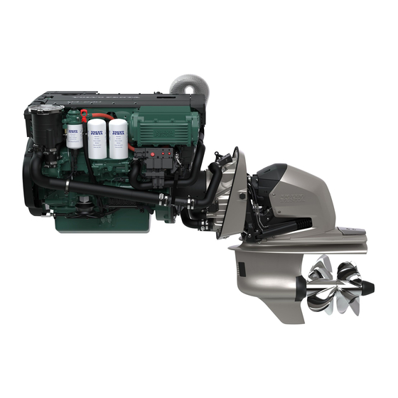
- Page 12 Presentation Orientation D4 with drive, starboard 1. Zinc anode 2. Cooling water intake 3. Zinc anode 4. Turbocharger 5. Crankcase ventilation filter 6. Aux Stop 7. Air filter 8. Compressor 9. EDC control module 10. Generator 11. Oil filler cap...
- Page 13 Presentation D4 with reverse gear, starboard 1. Turbocharger 2. Crankcase ventilation filter 3. Aux Stop 4. Air filter 5. EDC control module 6. Generator 7. Oil filler cap D4 with reverse gear, port 8. Sea water pump 9. Fuel filter 10.
- Page 14 Presentation D6 with drive, starboard 1. Zinc anode 2. Cooling water intake 3. Zinc anode 4. Turbocharger 5. Crankcase ventilation filter 6. Aux Stop 7. Air filter 8. Compressor 9. EDC control module 10. Generator 11. Oil filler cap D6 with drive, port 11.
- Page 15 Presentation D6 with reverse gear, starboard 1. Turbocharger 2. Crankcase ventilation filter 3. Air filter 4. Aux Stop 5. EDC control module 6. Generator 7. Oil filler cap D6 with reverse gear, port 8. Sea water pump 9. Fuel filter 10.
- Page 16 Instruments Battery (orange indication) The battery lamp lights up if the alternator is not charging. Stop the engine if this lamp lights up during operation. If the lamp lights up, this can be due to a fault in the electrical system or because the alternator drive belt is slack.
- Page 17 Instruments Coolant level (orange indication) The coolant lamp lights up when the coolant level is too low. Check coolant level. Please refer to “Maintenan- ce: Fresh water system”. Red warning indication, serious fault If the red warning indication is shown during opera- tion, a serious fault has occured.
- Page 18 This button is also used for: IMPORTANT! Always press the buttons firmly, and for at least one second each time. - Activation of the Volvo Penta Lowspeed/Trolling func- tion (optional). For more information please refer to chapter “Operation” section “Volvo Penta Lowspeed/ ...
- Page 19 Instruments EVC System Tachometer Introduction Volvo Penta EVC System Tachometer presents rele- vant boat and engine information to the helmsman. In- formation is presented on a display in the tachometer. Information is depending on engine model, number of sensors and type of accessories.
- Page 20 Instruments Trip menu (extra optional) In the TRIP MENU the user gets trip information from the EVC System and the user is allowed to select which view that should be presented in the EVC System Tachometers MAIN MENU as trip information. To get trip infor- mation following are required: Multisensor or NMEA 0183/NMEA 2000 compatible component (plotter, GPS, paddle wheel etc) Fuel level sender...
- Page 21 Instruments Gauges menu In GAUGES MENU the user gets information from analogue senders, placed on the engine. If the data is not available the parameter will not be displayed. When in GAUGES MENU, select view by turning NAVIGATION WHEEL. To select view as favorite, push NAVI- GATION WHEEL.
- Page 22 Maintenance: Engine general Checking exhaust line The exhaust line of drive installations must be in- spected every year with respect to corrosion between the hose (1) and the pipe (2). WARNING! Risk of water enter ing. The exhaust line must be inspected while the boat is on land. In case of serious corrosion damage, the pipe must be repaired or replaced with a new one.
- Page 23 Maintenance. Engine general Compressor. Checking oil Checking and topping up Unscrew and remove the dipstick. Wipe off oil. Screw the dipstick down fully and then remove it again. Check that the level oil is between the markings. If the dipstick is not screwed down fully the oil level will be slightly above the MIN marking if the oil level is cor- rect.
- Page 24 Then check the level again. Use only recommended grades of oil: Please refer to the “Technical Data” chapter. NOTE! The volume between MAX and MIN is apporx. 1.5 liter (0.4 US gals) for D4 and 3.5 liter ( 0.9 US gals) for D6.
- Page 25 Maintenance. Lubrication system Changing engine oil Always observe the recommended oil change interval. IMPORTANT! Only use a recommended grade of oil. Please refer to the “Technical Data” chapter. IMPORTANT! The oil level should always be between the MAX and MIN marks on the dipstick. Higher or lower oil level than permitted could lead to engine damage.
- Page 26 Maintenance. Lubrication system Changing oil filter and bypass filter. Change the oil filter and bypass filter during each oil change. Remember to hand the old filters in to a re-cycling station. WARNING! Hot oil and hot surfaces can cause burns.
- Page 27 The coolant should contain ethylene glycol of a good quality with a suitable chemical consistency for an ade- quate protection of the engine. Using anti-corrosion aditive exclusively is not permitted in Volvo Penta’s engines. Never use water by itself as coolant.
- Page 28 Maintenance: Electrical system Maintenance: Electrical system Battery. Charging Battery. Charging WARNING! WARNING! Danger of Danger of explosion! The batteries explosion! The batteries give off hydrogen gas during charging which give off hydrogen gas during charging which when mixed with air can when mixed with air can form an explosive gas form an explosive gas...
- Page 29 Maintenance: Electrical system Maintenance: Electrical system Electrical installations Electrical installations Leakage current from the electrical system can be Leakage current from the electrical system can be caused by incorrect installation of electrical equip- caused by incorrect installation of electrical equip- ment.
- Page 30 fit a Volv circuits, fit a Volvo Penta charge distributor o Penta charge distributor (ac- (ac- cessory) to the regular generator. cessory) to the regular generator.
- Page 31 Reverse gear Reverse gear The HS45AE/HS63AE/HS63VE/HS80/85A HS45AE/HS63AE/HS63VE/HS80/85AE/HS80/85VE reverse gear is hydraulic, which means E/HS80/85VE reverse gear is hydraulic, which means that ahead/as- that ahead/as- tern engagement tern engagement and disengagement is hydraulically activated. and disengagement is hydraulically activated. The reverse gear lubrication system The reverse gear lubrication system has an oil has an oil...
- Page 32 In case of emergency In case of emergency Diagnostic function Diagnostic function The diagnostic function monitors and checks that the engine, stern drive/reverse gear and EVC system function The diagnostic function monitors and checks that the engine, stern drive/reverse gear and EVC system function normally.
- Page 33 In case of emergency In case of emergency Malfunction message engine and EVC- Malfunction message engine and EVC- system system If the diagnostic function discovers a malfunction, it If the diagnostic function discovers a malfunction, it warns the driver by showing pop-ups in the tachom- warns the driver by showing pop-ups in the tachom- eter display and the buzzer will sound.
- Page 34 In case of emergency In case of emergency Faults list Faults list A faults list can be viewed from the MAIN MENU in A faults list can be viewed from the MAIN MENU in the tachometer, if a fault is registered. the tachometer, if a fault is registered.
- Page 35 Empty the water trap underneath the fuel filters, please refer to Please refer to “Maintenance: Fuel system”. • Please contact a Volvo Penta workshop if the fault remains. Seawater pressure Explanation: Seawater pressure too low. Reaction: Engine power is reduced.
- Page 36 Check coolant level. Please refer to "Maintenance: Freshwater system". • Check that no leakage occurs in auxiliary equipment connected to the engine cooling system. • Please contact a Volvo Penta workshop if the fault remains. Coolant pressure Explanation: Coolant pressure too low. Reaction: Engine power is reduced. Action: •...
- Page 37 Open the fuel taps and check that no leakage occurs. • Check that the fuel filters are not blocked. Please refer to “Maintenance: Fuel system” • Please contact a Volvo Penta workshop if the fault remains. Fuel temperature Explanation: Fuel temperature too high. Reaction: Engine power is reduced. Action: •...
- Page 38 Reaction: It is not possible to choose active helm station. Action: • Restart engine(s). • Please contact a Volvo Penta workshop if the fault remains. Check EVC system Explanation: Internal fault in the EVC system. Reaction: Engine power is reduced. Action: •...
- Page 39 4.5 bars (65 psi) Compressor Oil volume ..............0.1 liter (0.2 US pint) 0.1 liter (0.2 US pint) Oil grade..............Volvo Penta, part no. 1141641-9 Cooling system Thermostats open/fully open ........82°C/92°C 82°C/92°C Fresh water system volume, app......
- Page 40 Technical Data Lubrication system Oil volume, (incl. oil filter) ......... 12.5 liter (3.3 US gals) 20 liter (5.28 US gals) Oil volume, oil filter ..........1.6 liter (0.4 US gals) 1.6 liter (0.4 US gals) Oil volume between min. and max. markings ..1.5 liter (0.4 US gals) 3.5 liter (0.9 US gals) Oil grade ..............
- Page 42 7 0 0 2 - 6 0 h s i l g n E...
Need help?
Do you have a question about the D4 and is the answer not in the manual?
Questions and answers