Volvo Penta D4 Operator's Manual
Hide thumbs
Also See for D4:
- Operator's manual (150 pages) ,
- Service and maintenance manual (134 pages) ,
- Operator's manual (42 pages)
Table of Contents
Advertisement
Advertisement
Table of Contents

Related Manuals for Volvo Penta D4


Summary of Contents for Volvo Penta D4
- Page 1 OPERATOR’S MANUAL D4, D6...
- Page 2 This operator’s manual is also available in the following languages: Diese Betriebsanleitung ist auch auf Dit instructieboek kan worden besteld Deutsch erhältlich. in het Nederlands. Ein Bestellcoupon ist am Ende der Betriebs- De bestelcoupon vindt u achter in het instruc- anleitung zu finden.
- Page 3 Welcome aboard Volvo Penta marine engines are used all over the world today. They are used in all pos- sible operating conditions for professional as well as leisure purposes. That’s not sur- prising. After more than 90 years as an engine manufacturer and after delivering over 500,000 marine engines, the Volvo Penta name has become a symbol of reliability, technical in- novation, top of the range performance and long service life.
-
Page 4: Table Of Contents
Stopping the engine ........39-40 Stopping .............. 39 Laying up ............. 39 Cold weather precautions ........40 © 2004 AB VOLVO PENTA All rights to changes or modifications reserved. Printed on environmentally friendly paper. (Cover: Department of transport (shipping), license 9809095) -
Page 5: Safety Information
Read the operator’s manual carefully before operating or servicing the engine. If any- thing is unclear please contact your Volvo Penta dealer for assistance. This symbol is used in the book and on the engine to make you aware of safety information. -
Page 6: Boat Travel
Safety Information Safety precautions to be taken when operating the boat Your new boat Refueling Read operator’s manuals and other information sup- When refueling there is always a danger of fire and ex- plied with your new boat. Learn to operate the engine, plosion. - Page 7 Safety Information Carbon monoxide poisoning Most modern boats, however, are designed in such a When a boat is moving forward, it will cause a certain way that this problem is very rare. If suction should vacuum to form behind the boat. In unfortunate cir- arise anyway, do not open hatches or portholes at the cumstances, the suction from this vacuum can be so fore of the boat.
-
Page 8: Maintenance And Service
Loose clothing, hair, fingers or a mize the risk of fire and explosion. dropped tool can be caught in the rotating parts of the Using non-original Volvo Penta parts can result in fire engine and cause serious personal injury. Volvo Penta or explosion on board. - Page 9 Safety Information Hot surfaces and fluids Fuel system There is always a risk of burns when working with a Always use protective gloves when tracing leaks. Liq- hot engine. Beware of hot surfaces. For example: the uids ejected under pressure can penetrate body tissue exhaust pipe, Turbo unit, oil pan, charge air pipe, and cause serious injury.
-
Page 10: Introduction
Introduction This operator’s manual has been compiled to help you get the most from your Volvo Penta engine. It contains all the information you need in order to operate and maintain your engine safely and correctly. Please read the opera- tor’s manual carefully and learn how to operate the engine, controls and other equipment safely. -
Page 11: Certificated Engines
Warranty and Service book. Note that AB Volvo Penta’s liability is limited to that contained in the Warranty and Service Book. Read this book as soon as you take delivery of the engine. It contains important information about warranty cards, service and maintenance which you, the owner, must be aware of, check and carry out. -
Page 12: Identification Numbers
Introduction Identification numbers Always provide the engine and transmission identification numbers when ordering service or replacement compo- nents. The identification numbers are on an information decal located on the front edge of the engine. Note the informa- tion below. Make a copy of the page. Store the information so that it is available in event of the boat being stolen. Engine Product designation (1*) Serial number (2*) -
Page 13: Presentation
Presentation Volvo Penta’s D4 and D6 is developed from the latest design in modern diesel technology. The engine has com- mon rail injection system, double overhead camshafts, 4 valves per cylinder, turbocharger and aftercooler. To- gether with a large swept volume and the EVC system (Electronic Vessel Control), this results in world-class die- sel performance, combined with low emissions. -
Page 14: Engine Monitoring And Evc
Presentation Engine Monitoring and EVC system (Helm station Control Unit) (Helm station Control Unit) CAN bus (Power train Control Unit) (Engine Monitoring System) Engine monitoring system The engines are equipped with common rail system To protect the engine at too high coolant or charge air temperatures and boost pressure as well as oil pres- and electronically controlled injectors with an electron- sure the monitoring system reduces the amount of... - Page 15 Presentation Instrumentation The EVC system New types of instruments are introduced with EVC. The Electronic Vessel Control (EVC) system is a so The instruments use a serial communication bus. The called distributed system. The principle of a distribut- serial comminication bus in combination with EVC ed system is to have many small electonic units, radically reduces wiring and simplifies installation.
-
Page 16: Orientation
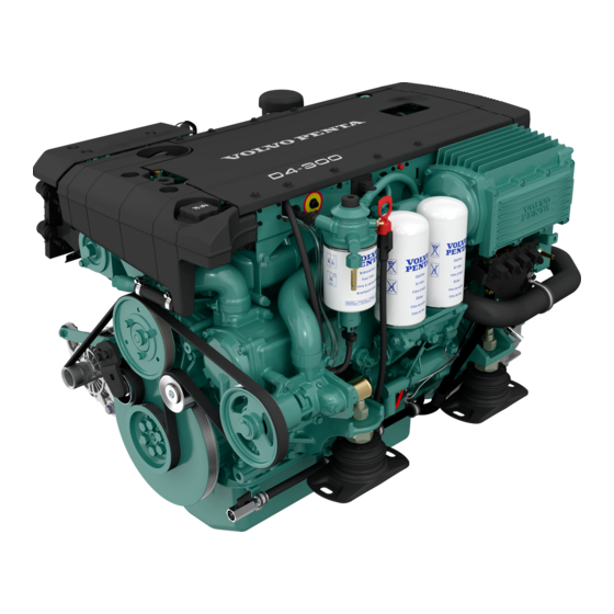
Presentation Orientation D4 with drive, starboard 1. Zinc anode 2. Cooling water intake 3. Zinc anode 4. Turbocharger 5. Crankcase ventilation filter 6. Aux Stop 7. Air filter 8. Compressor 9. EDC control module 10. Generator 11. Oil filler cap... - Page 17 Presentation D4 with revearse gear, starboard 1. Turbocharger 2. Crankcase ventilation filter 3. Aux Stop 4. Air filter 5. EDC control module 6. Generator 7. Oil filler cap D4 with revearse gear, port 8. Sea water pump 9. Fuel filter 10.
- Page 18 Presentation D6 with drive, starboard 1. Zinc anode 2. Cooling water intake 3. Zinc anode 4. Turbocharger 5. Crankcase ventilation filter 6. Aux Stop 7. Air filter 8. Compressor 9. EDC control module 10. Generator 11. Oil filler cap D6 with drive, port 11.
- Page 19 Presentation D6 with revearse gear, starboard 1. Turbocharger 2. Crankcase ventilation filter 3. Air filter 4. Aux Stop 5. EDC control module 6. Generator 7. Oil filler cap D6 with revearse gear, port 8. Sea water pump 9. Fuel filter 10.
-
Page 20: Instrumentation
Instruments This chapter describes the instrument and control panels sold by Volvo Penta for your engine. If you want to supplement the instrumentation, or if your boat is equipped with instruments not described here, or you are not sure about their function, please contact your Volvo Penta dealer. -
Page 21: Alarm Display
Instruments Alarm display The following warning lamps should never light up during operation. On the other hand, the warning lamps light up when the starter key is first turned to the drive position. Check that all lamps function. When the engine has star- ted, all lamps should have gone out. - Page 22 Instruments Battery. (orange indication) The battery lamp lights up if the alternator is not char- ging. Stop the engine if this lamp lights up during ope- ration. If the lamp lights up, this can be due to a fault in the electrical system or because the alternator drive belt is slack.
- Page 23 Instruments Coolant level (orange indication) The coolant lamp lights up when the coolant level is too low. Check coolant level. Please refer to “Maintenan- ce: Fresh water system”. Serious fault (red indication) The lamp lights up when a serious fault occurs. Please refer to the “In case of emergency”...
-
Page 24: Evc Control Panels
Instruments EVC control panel There are two versions of the EVC control panel, one for single engine installations and another for twin installations. Activation button Synchronization indication Used to activate the control panel, so that the engine The synchronization function automatically adjusts can be started and stopped. - Page 25 Instruments EVC-Display (extra optional) The Volvo Penta EVC-display is an on-board instru- ment for indication of engine operating values. The dis- play consists of a self-contained, computerised unit for fixed installation in a control panel. Indications are presented on a Liquid Crystal Display (LCD) screen.
-
Page 26: Controls
Controls This chapter describes the instrument panels sold by Volvo Penta for your engine. If your boat is equipped with controls which are not described here and you feel uncertain about the function, please contact the dealer you purchased the boat from. - Page 27 Controls Friction brake The control has a friction brake which can be adjusted as necessary to provide lighter or heavier lever action. Adjusting the friction brake: 1. Stop the engine. 2. Mover the control lever forwards so that the groove in the hub of the control lever is accessible.
- Page 28 Controls Two lever control. Mechanical Operation The two lever control has separate levers for shifting (1) and speed control (2). The control has a neutral position switch that only allows the engine to be started with the reversing gear in neutral. Black lever (1): N = Neutral position.
-
Page 29: Power Trim
Power Trim Your Volvo Penta drive is equipped with a hydraulic trim system, Power Trim, with which you can change the angle of the drive in relation to the transom. This will affect the running position of the boat and make it possible to optimize boat handling in various conditions. - Page 30 Power Trim Trim ranges In order to utilize the information gained from the trim instrument, it is essential to know about the different trim ranges and their uses. There are three trim rang- Trim range The trim range is used to obtain the best comfort at all running speeds (from start to maximum speed).
- Page 31 Power Trim Analogue trim instrument This instrument shows the current position of the drive. Beach range is marked with an orange zone and lift range with a red zone. 1. Trim range. 2. Beach range (orange). 3. Lift range (red).
-
Page 32: Starting The Engine
Starting the engine Make it a habit to give the engine and engine bay a visual check before starting. This will help you to discover quickly if anything abnormal has happened, or is about to happen. Also check that instruments and warning dis- plays show normal values after you have started the engine. -
Page 33: Starting Method
Starting the engine Starting method Put the reversing gear/stern drive in neutral Put the reversing gear in neutral by moving the control lever(s) to neutral at all control positions. Two lever control: Also check that the engine speed lever is in the idling position. Turn the ignition on Turn the starter key to position I to switch the ignition on. - Page 34 Starting the engine Start the engine Start using the ignition switch Turn the key to position III. Release the key and let it key spring back to position I as soon as the engine has started. Starting with the starter button Press the starter button.
-
Page 35: Operation
Operation Learn to handle the engine, controls and other equipment in a safe and correct manner before you cast off on your maiden voyage. Remember to avoid sudden or surprising rudder movements and gear shifting. There is a risk that passengers could fall over, or overboard. -
Page 36: Cruising Speed
Full throttle range: D4 ............3400–3600 rpm D6 ............3400–3600 rpm If the engine does not reach the full throttle range, this could be caused by a number of factors which are noted in the “Fault tracing”... -
Page 37: Changing Helm Station
This function must be enabled to permit the control panel to be changed during operation. The function can only be enabled by authorized Volvo Penta personnel. Please contact your Volvo Penta dealer. 1. Press the activation button (1) to unlock the system. -
Page 38: Operation
Operation Operation Shifting between forward and reverse should be done at idling. Shifting at higher engine speeds can be uncomfor- table for passengers and cause unnecessary stress on the stern drive/reversing gear, or cause the engine to stop. If you attempt to shift gear at an excessive engine speed, a safety function cuts in automatically, and delays shifting until engine speed has fallen to 1500 rpm. - Page 39 Operation Operating with the drive in the Trim range The Trim range is used to achieve maximum comfort under normal operation at all speeds from start to maximum speed. Since every boat has its own unique characteristics and will be effected in different ways by the factors in- volved, only general advice is given here on how to get the best trimming angle for your boat.
-
Page 40: Running Aground
If this is the case or if other damage has oc- curred to the drive it must be inspected at an autho- rized Volvo Penta workshop. If only the propeller has been damaged it must be replaced. Launch the boat and test drive. -
Page 41: Stopping The Engine
Stopping the engine The engine should be run for a few minutes at idle (in neutral) before turning it off. This will avoid boiling and even out the temperature. This is especially important if the engine has been operated at high engine speeds and loads. -
Page 42: Cold Weather Precautions
Stopping the engine Cold weather precautions To prevent freezing damage, the seawater system must be drained and the freshwater system coolant must have suffi- cient antifreeze protection. Refer to the cooling system sec- tion in chapter “Maintenance”. IMPORTANT! A poorly charged battery may burst as a result of freezing. -
Page 43: In Case Of Emergency
In case of emergency Despite regular maintenance according to the maintenance schedule and perfect operation, it may occur that a fault occurs which must be attended to before the boat can travel further. This chapter contains tips for rectifying some of the possible faults. There are safety functions which are activated when certain faults occur, to protect the engine. -
Page 44: Emergency Shifting
In case of emergency Emergency shifting If a fault occurs which prevents the revers gear from being operated (shifted) with the control lever, it is possible to shift manually, using the description be- low. Note. The descriptions refer to electrically shifted re- vers gear. -
Page 45: Engine Stop After Crash-Stop
In case of emergency Engine stop after crash-stop If the engine has stopped after a crash-stop, the follo- wing procedure has to be done before the boat can be manoeuvered: 1. Put the control levers in neutral position. 2. Acknowledge the alarm and stop the engine(s). 3. -
Page 46: Fault-Tracing
A number of symptoms and possible causes for engine disturbances are described in the table below. If faults or hitches arise that you cannot solve alone, you must always get in touch with your Volvo Penta dealer. WARNING! Read the safety directions for maintenance and service in the chapter “Safety information” before starting work. -
Page 47: Diagnostic Function
In case of emergency Diagnostic function The diagnostic function monitors and checks that the engine, stern drive/reversing gear and EVC system function normally. The diagnostic function has the following tasks: ● Discover and localize malfunctions ● Notify that malfunctions have been discovered ●... -
Page 48: Fault Codes
In case of emergency Fault codes Before the fault codes can be read out enter Service mode by pressing button D for about 5 sec. The D indication gives a steady light and indicator on alarm panel flashes with a orange/red light. The codes are flashed out on the D button indication. -
Page 49: Erasing Fault Codes
In case of emergency Erasing fault codes Any fault codes in the diagnostic function are automa- tically erased every time the starter key is turned to the stop position (S). NOTE! Stop the engine and check that the ignition key(s) is(are) in position 0 in all control positions. When system voltage is switched on again, the diag- nostic function checks to see whether there are any faults in the EVC system. -
Page 50: Maintenance Schedule
Maintenance schedule General information Your Volvo Penta engine and its equipment are designed for high reliability and long life. They are built to with- stand a marine environment, but also to have the smallest possible environmental impact. If given preventive maintenance, according to the maintenance schedule, and if Volvo Penta original spares are used, these qualities are retained and unnecessary malfunctions can be avoided. - Page 51 Maintenance schedule Every 200 hours / at least once a year, included in extended protection ● Crankcase ventrlation filter. Change ...............page 52 ● Air filter Change .....................page 52 ● Exhaust pipe. Inspection ................page 53 ● Drive belts. Checking of belt tension ..............page 53 ●...
- Page 52 Maintenance schedule Every 1200 hours / at least every 5 years: ● Drive belts. Change ..................page 53 Drive belt, compressor. Change ..............not shown ● Compressor. Change oil .................page 54 Heat exchanger. Inspection/Cleaning ............not shown Intercooler. Inspection/Cleaning ..............not shown Control cables and seals.
-
Page 53: Maintenance
Maintenance This chapter describes how to carry out the above maintenance. Read the instructions carefully before starting work. Maintenance intervals are contained in the chapter above: Maintenance schedule WARNING! Read the safety precautions for maintenance and service in the chapter: Safety Information, before starting work. - Page 54 Maintenance: Engine general Changing the air filter Remove the air filter cover. Remove the old air filter. Clean the air filter cover/housing if necessary. Take care not to allow impurities to enter the engine. Fit the new air filter and the air filter cover. Changing the crankcase ventilation filter Unscrew the lid and remove the old filter.
- Page 55 Maintenance. Engine general Checking the exhaust line. The exhaust line of drive installations must be inspec- ted every year with respect to corrosion between the hose (1) and the pipe (2). WARNING! Risk of water entering. The exhaust line must be inspected while the boat is on land. In case of serious corrosion damage, the pipe must be repaired or replaced with a new one.
- Page 56 Maintenance: Engine general Compressor. Checking oil Checking and topping up Unscrew and remove the dipstick. Wipe off oil. Screw the dipstick down fully and then remove it again. Check that the level oil is between the markings. If the dip- stick is not screwed down fully the oil level will be slightly above the MIN marking if the oil level is cor- rect.
-
Page 57: Lubrication System
Lubrication system IMPORTANT! With a new or reconditioned engine, the oil and oil filters must be changed after 20–50 hours of operation. Use only the recommended grades of oil. Oil change intervals can vary from 100 to 200 hours, depending on oil grade and sulphur content of the fuel. Note that oil change intervals must never exceed a period of 12 months. - Page 58 IMPORTANT! Do not fill the oil above the MAX level. NOTE! Between MAX and MIN there are apporx. 1,5 liter (0,4 US gals) for D4 and 3,5 liter ( 0,9 US gals) for D6. Engine oil. Change Always observe the recommended oil change interval.
- Page 59 Maintenance. Lubrication system Changing oil filter and bypass filter. Change the oil filter and bypass filter during each oil change. Remember to hand the old filters in to a re-cycling station. WARNING! Hot oil and hot surfaces can cause burns. 1.
-
Page 60: Freshwater System
Freshwater system The freshwater system is the engine's internal cooling system. It is a closed system and must always be filled with a coolant that protects it against internal corrosion and freezing when the climate demands. Freshwater circulates from the circulation pump in the engine block, around the cylinders and on to the turbochar- ger and exhaust pipe. - Page 61 IMPORTANT! Ethylene glycol must not be mixed with other kinds of glycol. A mixture of 40% Volvo Penta coolant (ethylene glycol) and 60% water (to ASTM D4985) shall always be used, all year round. NOTE! Mix the glycol with water in a separate vessel before filling the system.
- Page 62 Maintenance. Freshwater system Draining the fresh water system Remove the filler cap on the expansion tank (to allow the coolant to run out faster). Use a suitable receptacle while draining. There is a hose mounted on the intercooler. Move the hose and connect it to the drain nipple (1).
-
Page 63: Seawater System
Seawater system The seawater system is the boat’s external cooling system. On engines with drives, the seawater pump draws in water via the drive, through the control system oil cooler to the seawater pump, after which the water passes the seawater filter before being pumped through the fuel cooler, intercooler, engine oil cooler and heat exchanger. - Page 64 Maintenance. Seawater system Cleaning seawater filter. WARNING! Risk for water penetration. Screw off cover (1) and remove seal plate (2). Lift out and clean the insert (3). IMPORTANT! If the boat is used in water that has a lot of contaminants, seaweed etc. the filter must be checked more frequently than indicated in the maintenance schedule.
- Page 65 Maintenance. Seawater system Checking/Changing zinc anodes WARNING! Risk of water entering. Close the sea- water cock before starting work on the seawater system. 1. Close the seawater cock. 2. Drain the seawater as described in ”Draining the seawater system”. 3. Remove the zinc anodes in the heat exchanger and the intercooler.
- Page 66 Maintenance. Seawater system Seawater system. Cleaning and inhibiting To prevent the build up of deposits and salt crystals in the seawater system it must be flushed with freshwa- ter. When the boat is laid up it must also be inhibited. WARNING! Risk of water penetration.
-
Page 67: Fuel System
Fuel system The engine fuel system is a so-called common rail-system. The advantage of the common rail-system is that the engine control unit controls the timing and fuel amount, this mean better emission control and a smooth running engine. All work on the engine common rail-system must be carried out at an authorized workshop. Use only the recom- mended grade of fuel: See the chapter “Technical Data”. - Page 68 Maintenance. Fuel system Bleeding the fuel system The fuel system must be bled e.g. after changing fuel filter, if the fuel tank has been run dry and after long stops. WARNING! Never detach the pressure pipes. 1. Attach a transparent hose to the air vent valve (1). Lead the hose to a suitable receptacle to avoid spillage.
- Page 69 Maintenance. Fuel system Fuel pre-filter. Replacing filter insert Close fuel cock at the fuel tank. Position a container under the fuel filter. Remove the cover by slackening off screw (1). Replace insert and reinstall cover. Open fuel cock. Vent fuel system.
-
Page 70: Electrical System
IMPORTANT! Never break the circuit with the main switches while the engine is running. Fuses D4/D6 12-volt system The engine is fitted with fully automatic circuit breakers. The circuit breakers cut the power if the electrical system is overloaded. - Page 71 Also check that all electrical connections are dry and free of oxidation and that there are no loose connec- tions. If necessary, spray these connections with a water-repellent spray (Volvo Penta Universal oil). Battery. Maintenance WARNING! Risk of fire and explosion. Never al- low an open flame or electric sparks near the battery or batteries.
- Page 72 Maintenance: Electrical system Battery. Charging WARNING! Danger of explosion! The batteries give off hydrogen gas during charging which when mixed with air can form an explosive gas – oxyhydrogen A short-circuit, naked flame or spark can cause a large explosion. Ensure that the ventilation is good.
- Page 73 Maintenance: Electrical system Electrical installations Leakage current from the electrical system can be caused by incorrect installation of electrical equip- ment. Leakage current can knock out the galvanic protection of components such as the drive, propeller, propeller shaft, rudder stock and keel and cause dam- age by electrolytic corrosion.
- Page 74 All equipment connected to the auxiliary battery should have separate switches. To simultaneously charge two independent battery circuits, fit a Volvo Penta charge distributor (ac- cessory) to the regular generator.
-
Page 75: Reverse Gear
The reverse gears is equipped with solenoid valves for electronically controlled shifting. IMPORTANT! Volvo Penta recommends the installation of a seawater filter to guarantee the proper coolant water flow to the engine and reverse gear. Contaminants in the seawater will otherwise foul the reverse gear radiator and other cooling system components. - Page 76 Maintenance. Reverse gear Propeller shaft seal If the boat has a Volvo Penta shaft the shaft seal must be vented and lubricated directly after launching. Vent the bushing by pressing it together while press- ing down on the shaft until water appears. Then press in approx.
-
Page 77: Drive
Drive Your drive is protected against galvanic corrosion. This protection consists of two-three layers of paint, sacrificial anodes and ground braids. The ground braids maintain a connection between the different components of the drive. A broken connection can result in the rapid corrosion of an individual component even though the protection is otherwise effective. - Page 78 Maintenance: Drive Checking oil level Trim up the drive to 35°. Remove the cover (1) and the plug (2). IMPORTANT! Always trim up the drive to 35° when checking the oil level. The oillevel must always be at the top of the oil filler cap (3).
- Page 79 The drive must be dismantled from the suspen- sion fork in order to change the joint bellows. Dismant- ling the drive requires knowledge and special tools. Contact your Volvo Penta service centre. Replacing exhaust bellows Check the condition of the exhaust bellows once a year.
-
Page 80: Steering
NOT open lower helm pump. Only check the oil level at the upper helm station. Normally, the oil level will WARNING! Use only Volvo Penta recommended not change, ”oil consumption” in one year is negligible. fluid and grade. Never top up the steering system with fluid of unknown grade. - Page 81 The par- allel strut is a vital safety component, damage may affect steering characteristics. In the worst case steering could be lost altogether. Never align or weld a damaged parallel strut. Please contact your nearest authorized Volvo Penta workshop for assistance.
-
Page 82: Propellers
Assembly Propellers. DPR/DPH drive 1. Lubricate both propeller hubs. Use Volvo Penta NB! A tool for removing and fitting the propellers is grease 828250. supplied together with the drive (see figure). -
Page 83: Laying Up/Launching
Laying up/Launching Before taking the boat out of the water for winter/out-of-season storage have an authorized Volvo Penta workshop inspect the engine and other equipment. Have any necessary repairs or service work carried out so that your boat is in top condition for the new season. -
Page 84: Bringing Out Of Winter Storage
Laying up/Launching Bringing out of storage ● Check oil level in the engine and drive/reverse ● Paint the drive and hull: See next page. gear. Top up if necessary. If there is inhibiting oil in the system drain and fill with new oil, change oil ●... -
Page 85: Painting The Drive And Underwater Hull
Wash off using thinners or similar. Any pores in the surface should be filled and sanded down. Paint using Volvo Penta original primer and topcoat. Let the paint dry. A further two coats of Volvo Penta anti-fouling primer should then be ap- plied. -
Page 86: Fault Code Register
Empty the water trap underneath the fuel filters, please refer to the “In case of emergency” chapter ”Water in fuel” • Contact a Volvo Penta workshop if the fault remains. 1.2.4 Explanation: Fault in engine speed sensor on flywheel. Reaction: Engine power is reduced. Engine is difficult to start. - Page 87 Check that the sea water filter is not blocked. Please refer to “Maintenance: Sea water system”. • Check the impeller in the sea water pump. Please refer to “Maintenance: Sea water system”. • Check that no leakage occurs. • Contact a Volvo Penta workshop if the fault remains.
- Page 88 • Open the fuel taps and check that no leakage occurs. • Check that the fuel filters are not blocked. Please refer to “Maintenance: Fuel system” • Contact a Volvo Penta workshop if the fault remains. 1.7.1–1.7.6 Explanation: Injector system failure, injector 1–6.
- Page 89 Check the fuel level. • Check fuel cooler. • Check that no leakage occurs. • Please contact a Volvo Penta workshop if the fault remains. 1.9.9 Explanation: Internal system fault in engine. Reaction: Action: • If the engine can not be operated from the chosen control panel, use an alternative control panel.
- Page 90 Reaction: Cannot engage gears. Engine in emergency mode. Action: • Emergency shifting, see chapter "In case of emergeny". • Please contact a Volvo Penta workshop if the fault remains. 2.4.5 Explanation: Faulty solenoid, primary. Reaction: Cannot engage gears. Engine in emergency mode. Action: •...
- Page 91 Action: • Switch the ignition off, and repeat the calibration procedure. • Check that the control levers are approved by Volvo Penta and correctly installed. • Please contact a Volvo Penta workshop if the fault remains. • Check that the control levers are approved by Volvo Penta.
- Page 92 If the engine can not be operated from the chosen control panel, use an alternative control panel. • Switch the ignition off, and repeat the calibration procedure. • Check that the control levers are approved by Volvo Penta and correctly installed. • Please contact a Volvo Penta workshop. 3.9.9 Explanation: Internal fault in the EVC system.
-
Page 93: Technical Data
Technical Data Engine General information Engine designation ..........D4-210i-A, D4-210A-A D6-310i-A, D6-310A-A D4-260i-A, D4-260A-A D6-280i-A, D6-280A-A D6-350A-A,D6-370i-A Idling speed ............700 rpm 600 rpm Swept volume ............3,7 liter (1,0 US gals) 5,5 liter (1,5 US gals) Injection sequence .......... -
Page 94: Fuel Specification
+ + + + + 14 Compressor Oil volume .............. 0,1 liter (0,2 US pint) 0,1 liter (0,2 US pint) Oil grade..............Volvo Penta, part no. 1141641-9 Cooling system Thermostats open/fully open ........ 82°C/92°C 82°C/92°C Fresh water system volume, app...... -
Page 95: Drive
Technical Data Drive Oil volume ............5.4 liters (1.4 US gals) Oil volume between min. and max. markings ............ 0.2 liter (0.4 US pint) Oil grade and viscosity ........VP 1141634 (API GL5 SAE 75W /90) Synthetic* * NOTE. At long operational hours in warm waters (above 25°C/77°F) VP 1141666 (API GL SAE 75W/ 140) Synthetic oil should be used. - Page 96 Notes...
- Page 97 Notes...
- Page 98 Notes...
- Page 99 ✂ Yes please, I would like an operator’s manual in English at no charge. Publication number: 7743883 Post or fax this coupon to: Document & Distribution Center Name Order Department ARU2, Dept. 64620 Address SE-405 08 Göteborg Sweden Fax: +46 31 545 772 Orders can also be placed via the Internet: http://www.volvopenta.com/...
- Page 100 ✂ Sí gracias, deseo recibir gratuitamente un libro de instrucciones en español. Número de publicación: 7743887 Franquear o enviar fax a: Document & Distribution Center Nombre Order Department ARU2, Dept. 64620 Dirección SE-405 08 Göteborg Suecia Fax: +46 31 545 772 El pedido puede hacerse tam- bién por internet: http://www.volvopenta.com/...
- Page 101 ✂ Ja graag, Ik wil kosteloos een instructieboek in het Nederlands ontvangen. Publicatienummer: 7743892 Stuur of fax de coupon naar: Document & Distribution Center Naam Order Department ARU2, Dept. 64620 Adres SE-405 08 Göteborg Zweden Fax: +46 31 545 772 U kunt ook bestellen via internet: http://www.volvopenta.com/...
- Page 102 ✂ Sim, obrigado(a)! Gostaria de receber gratuitamente um manual de instruções em português. Número de publicação: 7743893 Envie o talão pelo correio ou um fax para: Nome Document & Distribution Center Order Department Endereço ARU2, Dept. 64620 SE-405 08 Göteborg Sweden Fax: +46 31 545 772 A encomenda também pode...
Need help?
Do you have a question about the D4 and is the answer not in the manual?
Questions and answers