
Related Manuals for Allied Telesis AT-FS909M


Summary of Contents for Allied Telesis AT-FS909M
-
Page 1: Installation Guide
AT-FS909M AT-FS917M AT-FS926M Fast Ethernet Switches Installation Guide 613-001985 Rev A... - Page 2 Telesis, Inc. be liable for any incidental, special, indirect, or consequential damages whatsoever, including but not limited to lost profits, arising out of or related to this manual or the information contained herein, even if Allied Telesis, Inc. has been advised of, known, or should have known, the possibility of such damages.
-
Page 3: Electrical Safety And Emissions Standards
Electrical Safety and Emissions Standards This product meets the following standards. U.S. Federal Communications Commission Radiated Energy Note: This equipment has been tested and found to comply with the limits for a Class A digital device pursuant to Part 15 of FCC Rules. -
Page 4: Translated Safety Statements
Translated Safety Statements Important: The indicates that a translation of the safety statement is available in a PDF document titled Translated Safety Statements posted on the Allied Telesis website at www.alliedtelesis.com/support. -
Page 5: Table Of Contents
Contents Preface ................................11 Symbol Conventions ..........................12 Contacting Allied Telesis..........................13 Chapter 1 : Overview ............................. 15 Features ..............................16 Twisted-Pair Ports ..........................16 SFP Slots............................. 16 LEDs..............................17 Installation Options ..........................17 MAC Address Table ..........................17 Front and Back Panels..........................18 Management Software .......................... - Page 6 Contents...
- Page 7 Figures Figure 1: AT-FS909M, AT-FS917M, and AT-FS926M Front Panels ................... 18 Figure 2: AT-FS909M, AT-FS917M, and AT-FS926M Back Panels ................... 19 Figure 3: STATUS LEDs..............................23 Figure 4: MODE LEDs ................................. 24 Figure 5: Port LEDs ................................25 Figure 6: SFP Slot LEDs ..............................26 Figure 7: Shipping Package Contents ..........................
- Page 8 List of Figures...
- Page 9 Tables Table 1. Combo Ports .................................22 Table 2. POWER LED Functional Description ........................23 Table 3. FAULT LED Functional Description ........................24 Table 4. MODE LED Functional Descriptions ........................25 Table 5. Port LED Functional Descriptions .........................25 Table 6. SFP Slot LED Functional Descriptions .........................26 Table 7.
- Page 10 List of Tables...
-
Page 11: Preface
Preface This guide contains the installation instructions for the AT-FS909M, AT- FS917M, and AT-FS926M Fast Ethernet Switches. This preface contains the following sections: “Symbol Conventions” on page 12 “Contacting Allied Telesis” on page 13 ... -
Page 12: Symbol Conventions
Symbol Conventions This document uses the following conventions: Note Notes provide additional information. Caution Cautions inform you that performing or omitting a specific action may result in equipment damage or loss of data. Warning Warnings inform you that performing or omitting a specific action may result in bodily injury. -
Page 13: Contacting Allied Telesis
AT-FS909M, AT-FS917M, and AT-FS926M Switches Installation Guide Contacting Allied Telesis If you need assistance with this product, you may contact Allied Telesis technical support by going to the Support & Services section of the Allied Telesis web site at www.alliedtelesis.com/support. You can find links for the following services on this page: 24/7 Online Support —... -
Page 15: Chapter 1 : Overview
Chapter 1 Overview This chapter provides descriptions of the AT-FS909M, AT-FS917M, and AT-FS926M Layer 2 Fast Ethernet Switches and contains the following sections: “Features” on page 16 “Front and Back Panels” on page 18 “Management Software” on page 20 ... -
Page 16: Features
RJ-45 connectors SFP Slots All three switches support both 100Base-FX and 1000Base-SX/LX transceivers. The switches support slots for SFPs as follows: One SFP slot on the AT-FS909M and AT-FS917M switches Two SFP slots on the AT-FS926M switch Note The AT-FS900M Series SFP slots are paired with twisted pair ports on the switch to form combo ports. -
Page 17: Leds
If installing the switch in an equipment rack, rack mounting equipment provided with the switch depends on the switch model as follows: AT-FS909M and AT-FS917M: rack mounting equipment must be purchased separately. The rack mounting kit model number is AT- RKMT-J05. -
Page 18: Front And Back Panels
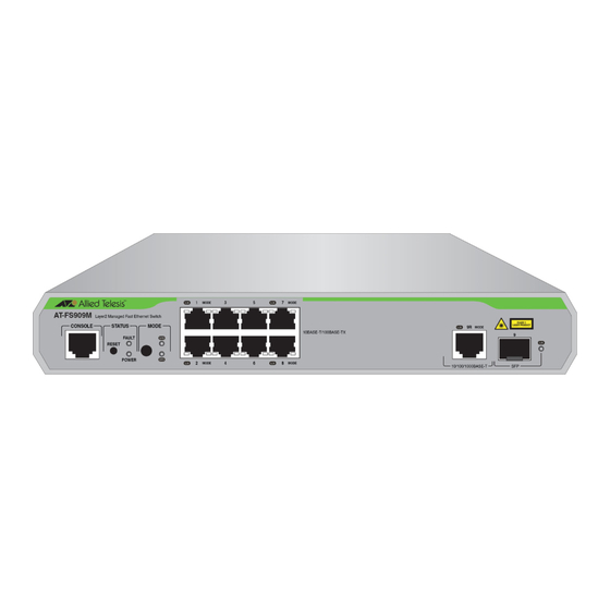
Chapter 1: Overview Front and Back Panels Figure 1 illustrates the front panels of the AT-FS909M, AT-FS917M, and AT-FS926M Fast Ethernet Switches. AT-FS909M Console Port Reset Button 10/100/100Base-T 10/100/1000Base-T SFP LED Status LEDs Twisted-Pair Ports Combo Port with Mode with Port LEDs... -
Page 19: Figure 2: At-Fs909M, At-Fs917M, And At-Fs926M Back Panels
AT-FS909M, AT-FS917M, and AT-FS926M Switches Installation Guide Figure 2 illustrates the back panels of the AT-FS909M, AT-FS917M, and AT-FS926M switches. AT-FS909M & AT-FS917M AC Input AT-FS926M AC Input Figure 2. AT-FS909M, AT-FS917M, and AT-FS926M Back Panels... -
Page 20: Management Software
Chapter 1: Overview Management Software The switches are shipped with the ATPro management software pre- installed. The software provides a web-browser interface for in-band, over- the-network management. In the unlikely event that the management software becomes corrupted or damaged on the switch, you can download the software from the Allied Telesis corporate web site and reinstall it on the switch. -
Page 21: Twisted-Pair Ports
AT-FS909M, AT-FS917M, and AT-FS926M Switches Installation Guide Twisted-Pair Ports The AT-FS909M, AT-FS917M, and AT-FS926M Layer 2 Fast Ethernet Switches feature 8, 16, and 24 twisted pair ports, respectively. All ports are 10Base-T and 100Base-TX compliant. You can set the port speeds and duplex modes either automatically with IEEE 802.3u Auto-Negotiation or... -
Page 22: Combo Ports
Chapter 1: Overview Combo Ports The AT-FS909M and AT-FS917M Switches have one combo port, and the AT-FS926M Switch has two combo ports. Each combo port consists of one 10/100/1000Base-T twisted pair port and one slot for an optional 100Base-FX or 1000Base-SX/LX SFP transceiver. The twisted pair ports are identified with the letter “R”... -
Page 23: Leds
AT-FS909M, AT-FS917M, and AT-FS926M Switches Installation Guide LEDs There are four types of LEDs on the AT-FS900M Series switches: “STATUS LEDs” “MODE LEDs” on page 24 “Port LEDs” on page 25 “SFP Slot LEDs” on page 26 ... -
Page 24: Mode Leds
Chapter 1: Overview FAULT LED The FAULT LED reports any conditions on the switch that are not normal. Table 3 describes the states of the FAULT LED. Table 3. FAULT LED Functional Description State Description Normal switch operation. Steady Abnormal system operation. Flashing One of following: Firmware downloading and being... -
Page 25: Port Leds
AT-FS909M, AT-FS917M, and AT-FS926M Switches Installation Guide Table 4. MODE LED Functional Descriptions State Description Steady SPEED is the selected mode. Ports display Green SPEED status. SPEED SPEED is not the selected mode. Ports display DUPLEX status. Steady DUPLEX is the selected mode. Ports display... -
Page 26: Sfp Slot Leds
Chapter 1: Overview Table 5. Port LED Functional Descriptions State Description The maximum operating speed of the port is 10 Mbps or link not established. Speed Steady The maximum operating speed of the Green port is 100 Mbps. Half-duplex link established or link not established. -
Page 27: Reset Button
AT-FS909M, AT-FS917M, and AT-FS926M Switches Installation Guide Reset Button Pressing the Reset button resets your switch. The Reset button is located next to the STATUS LEDs. See Figure 3 on page 23. This initiates a system reboot of the switch and reloads the current configuration file. -
Page 28: Mode Button
Chapter 1: Overview Mode Button Use the Mode button to select whether the Port LEDs display the Link Activity or speed and duplex status. The Mode button is located next to the MODE LEDs. See Figure 4 on page 24. -
Page 29: Power Supply
AT-FS909M, AT-FS917M, and AT-FS926M Switches Installation Guide Power Supply Each switch has an internal power supply with a single AC power supply socket on the back panel. To power the switch on or off, connect or disconnect the power cord provided with the switch. A power cord is supplied with the switch. - Page 30 Chapter 1: Overview...
-
Page 31: Chapter 2 : Installation
Chapter 2 Installation This chapter contains the following sections: “Reviewing Safety Precautions” on page 32 “Selecting a Site for the Switch” on page 35 “Cable Specifications” on page 36 “Unpacking the Switch” on page 37 “Installing the Power Cord Retaining Clip” on page 39 ... -
Page 32: Reviewing Safety Precautions
available in a PDF document titled Translated Safety Statements posted on the Allied Telesis website at www.alliedtelesis.com/ support. Warning To prevent electric shock, do not remove the cover. No user- serviceable parts inside. - Page 33 AT-FS909M, AT-FS917M, and AT-FS926M Switches Installation Guide Caution Air vents must not be blocked and must have free access to the room ambient air for cooling. Warning Operating Temperature. The AT-FS909M and AT-FS917M are designed for a maximum ambient temperature of 50° C.
- Page 34 Chapter 2: Installation Warning Reliable earthing of rack-mounted equipment should be maintained. Particular attention should be given to supply connections other than direct connections to the branch circuits (for example, use of power strips). ...
-
Page 35: Selecting A Site For The Switch
AT-FS909M, AT-FS917M, and AT-FS926M Switches Installation Guide Selecting a Site for the Switch Observe the following requirements when choosing a site for your switch: If you plan to install the switch in an equipment rack, verify that the rack is safely secured and will not tip over. Devices in a rack should be installed starting at the bottom, with the heavier devices near the bottom of the rack. -
Page 36: Cable Specifications
Chapter 2: Installation Cable Specifications Table 7 contains the cable specifications for the twisted-pair ports. Table 7. Twisted-Pair Cabling and Distances Maximum Speed Type of Cable Operating Distance 10 Mbps Standard TIA/EIA 568-B-compliant 100 m (328 ft) Category 3 or better shielded or unshielded cabling with 100 ohm impedance and a frequency of 16 MHz. -
Page 37: Unpacking The Switch
3. In addition to the switch, verify that the shipping container includes the following items shown in Figure 7 on page 38. Note For the AT-FS909M and AT-FS917M, rack mounting equipment (brackets and screws) is not included in the shipping package and must be purchased separately. Its rack mounting kit model number... -
Page 38: Figure 7: Shipping Package Contents
Chapter 2: Installation Two equipment rack brackets (not included in AT- FS909M or AT-FS917M package) Four bracket screws (not included in AT- FS909M or AT-FS917M package) Two retaining plates (FS926M only) Retaining clip Management cable Four rubber feet (pre-installed) (for desktop installation) One regional AC power cord One or two SFP slot... -
Page 39: Installing The Power Cord Retaining Clip
AT-FS909M, AT-FS917M, and AT-FS926M Switches Installation Guide Installing the Power Cord Retaining Clip Perform the following procedure to install the power cord retaining clip on the AT-FS900M switch: Note The AT-FS926M requires installation of retaining plates in addition to the clip, as noted in the following procedure. -
Page 40: Figure 10: Installing Retaining Plates On The Power Connector
Chapter 2: Installation Figure 10. Installing Retaining Plates on the Power Connector 3. Install the clip on the AC power connector on the back panel of the switch. With the “u” of the clip facing down, press the sides of the clip toward the center and insert the short ends into the holes in the retaining bracket, as shown in Figure 11. -
Page 41: Installing The Switch On A Desktop Or Table
AT-FS909M, AT-FS917M, and AT-FS926M Switches Installation Guide Installing the Switch on a Desktop or Table You may install the switches on a desktop or table, or in a standard 19- inch equipment rack. To install the switch in a rack, see “Installing the Switch in an Equipment Rack”... -
Page 42: Installing The Switch In An Equipment Rack
Installing the Switch in an Equipment Rack Note The AT-FS926M rack mounting hardware is included in the shipping package. However, the AT-FS909M and AT-FS917M rack mounting equipment must be purchased separately. The rack mounting kit model number is AT-RKMT-J05. To install the switch in a standard 19-inch equipment rack, perform the following procedure: 1. - Page 43 AT-FS909M, AT-FS917M, and AT-FS926M Switches Installation Guide 4. Go to “Installing SFP Transceivers” on page 44 or skip to “Cabling the Switch” on page 47 if not installing SFP transceivers.
-
Page 44: Installing Sfp Transceivers
Chapter 2: Installation Installing SFP Transceivers To install an SFP transceiver, perform the following procedure: Note The transceiver can be hot-swapped; you do not need to power off the switch to install a transceiver. However, you should always remove the cables before removing the transceiver. Note You should always install the transceiver before connecting the fiber-optic cables to it. -
Page 45: Figure 15: Inserting The Sfp
AT-FS909M, AT-FS917M, and AT-FS926M Switches Installation Guide 4. Slide the transceiver into the SFP slot until it clicks into place. See Figure 15. Figure 15. Inserting the SFP 5. Verify that the handle on the transceiver is in the upright position, as shown in Figure 16. - Page 46 Chapter 2: Installation For information on the cable specifications of the SFP, consult the documentation shipped with the SFP. 7. Go to “Cabling the Switch” on page 47.
-
Page 47: Cabling The Switch
AT-FS909M, AT-FS917M, and AT-FS926M Switches Installation Guide Cabling the Switch Observe the following guidelines when connecting twisted-pair and fiber- optic cables to the ports on the switch: The connector on the cable should fit snugly into the port on the ... -
Page 48: Powering On The Switch
Chapter 2: Installation Powering On the Switch To power on the switch, perform the following procedure: 1. Lift up the retaining clip and insert the power cord into the AC power connector on the back of the switch, as shown in Figure 17. Figure 17. - Page 49 AT-FS909M, AT-FS917M, and AT-FS926M Switches Installation Guide Note Pluggable Equipment. The socket outlet shall be installed near the equipment and shall be easily accessible. 4. Verify that the POWER LED is green. If the LED is OFF, see Chapter 3, “Troubleshooting”...
- Page 50 Chapter 2: Installation...
-
Page 51: Chapter 3 : Troubleshooting
This chapter contains information on how to troubleshoot the switch if a problem occurs. Note For further assistance, please contact Allied Telesis Technical Support at www.alliedtelesis.com/support. Problem 1: The POWER LED on the front of the switch is off. Solutions: The unit is not receiving power. Try the following: Verify that the power cord is securely connected to the power ... - Page 52 Chapter 3: Troubleshooting Verify that you are using the appropriate category of twisted-pair cable: Category 3 or better for 10 Mbps operation and Category 5 and Category 5E for 100 Mbps operation. Problem 3: The Link Activity LED for an SFP transceiver is off. Solutions: The fiber-optic port on the transceiver is unable to establish a link to a network device.
-
Page 53: Appendix A : Technical Specifications
2.1 kg (4.63 lbs) Environmental Specifications Table 10. Environmental Specifications Operating Temperature: 0° C to 50° C (32° F to 122° F) AT-FS909M, AT-FS917M Operating Temperature: 0° C to 40° C (32° F to 104° F) AT-FS926M Storage Temperature -20° C to 60° C (-4° F to 140° F) -
Page 54: Power Specifications
5% to 95% non-condensing Operating Altitude Range Up to 2,000 m (6,562 ft) Power Specifications Input Supply Voltage - 100-240 VAC, 50 - 60 Hz Table 11. Power Specifications AT-FS909M 11 W AT-FS917M 13 W AT-FS926M 16 W Safety and Electromagnetic Emissions Certifications Table 12. -
Page 55: Connectors And Port Pinouts
AT-FS909M, AT-FS917M, and AT-FS926M Switches Installation Guide Connectors and Port Pinouts This section lists the connectors and connector pinouts. Figure 18 illustrates the pin layout for an RJ-45 connector and port. Figure 18. RJ-45 Connector and Port Pin Layout Table 13 lists the RJ-45 pin signals when a twisted-pair port is operating in the MDI configuration. - Page 56 Appendix A: Technical Specifications...
Need help?
Do you have a question about the AT-FS909M and is the answer not in the manual?
Questions and answers