
Related Manuals for Allied Telesis AT-FS980M/9


Summary of Contents for Allied Telesis AT-FS980M/9
-
Page 1: Installation Guide
FS980M Series FAST ETHERNET MANAGED SWITCHES AT-FS980M/9 AT-FS980M/9PS AT-FS980M/18 AT-FS980M/18PS AT-FS980M/28 AT-FS980M/28PS AT-FS980M/52 AT-FS980M/52PS Installation Guide 613-002229 Rev. A... - Page 2 Telesis, Inc. be liable for any incidental, special, indirect, or consequential damages whatsoever, including but not limited to lost profits, arising out of or related to this manual or the information contained herein, even if Allied Telesis, Inc. has been...
- Page 3 Electrical Safety and Emissions Standards This section contains the following: “US Federal Communications Commission” “Industry Canada” “Emissions, Immunity and Electrical Safety Standards” on page 4 “Translated Safety Statements” on page 4 US Federal Communications Commission Radiated Energy Note This equipment has been tested and found to comply with the limits for a Class A digital device pursuant to Part 15 of FCC Rules.
-
Page 4: Translated Safety Statements
EMC (Immunity) EN55024, EN61000-3-2, EN61000-3-3 Electrical Safety UL60950-1 ( ), EN60950-1 (TUV) Translated Safety Statements Important: The indicates that translations of the safety statement are available in the PDF document Translated Safety Statements posted on the Allied Telesis website at alliedtelesis.com/support. - Page 5 Contents Preface ....................................7 Document Conventions ..............................8 Contacting Allied Telesis ..............................9 Chapter 1: Overview ................................11 Product Overview ................................12 AT-FS980M/9 Switch .............................12 AT-FS980M/9PS Switch ............................13 AT-FS980M/18 Switch ............................14 AT-FS980M/18PS Switch ............................15 AT-FS980M/28 Switch ............................16 AT-FS980M/28PS Switch ............................17 AT-FS980M/52 Switch ............................18 AT-FS980M/52PS Switch ............................19 SFP Slots ................................20...
- Page 6 Contents Port Prioritization ..............................33 LEDs ....................................35 System LEDs................................35 10/100Base-TX Twisted Pair Port LEDs ........................36 10/100/1000Base-TX Twisted Pair Port LEDs .......................37 SFP Slot LED .................................38 Console Port ..................................39 Chapter 2: Installing the Switch ............................41 Reviewing Safety Precautions ............................42 Choosing a Site for the Switch ............................46 Unpacking the Switch ..............................47 Installing the Switch on a Table or Desktop........................49 Installing the Switch on a Wall ............................50...
-
Page 7: Preface
Fast Ethernet switches. The switch models included in this manual are: AT-FS980M/9 AT-FS980M/9PS AT-FS980M/18 AT-FS980M/18PS AT-FS980M/28 AT-FS980M/28PS AT-FS980M/52 AT-FS980M/52PS The preface contains the following sections: “Document Conventions” on page 8 “Contacting Allied Telesis” on page 9 ... -
Page 8: Document Conventions
Preface Document Conventions This document uses the following conventions: Note Notes provide additional information. Caution Cautions inform you that performing or omitting a specific action may result in equipment damage or loss of data. Warning Warnings inform you that performing or omitting a specific action may result in bodily injury. -
Page 9: Contacting Allied Telesis
FS980M Series Fast Ehternet Managed Switches Installation Guide Contacting Allied Telesis If you need assistance with this product, you may contact Allied Telesis technical support by going to the Support & Services section of the Allied Telesis web site at www.alliedtelesis.com/support. You can find links for the following services on this page: 24/7 Online Support —... - Page 10 Preface...
-
Page 11: Chapter 1: Overview
Chapter 1 Overview This chapter contains the following sections: “Product Overview” on page 12 “SFP Modules” on page 22 “Model Naming Conventions” on page 23 “10/100Base-TX Twisted Pair Ports” on page 24 “10/100/1000Base-T Twisted Pair Ports” on page 27 ... -
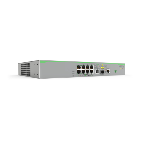
Page 12: Product Overview
10/100/1000Base-TX Ports SFP slot Figure 1. AT-FS980M/9 Switch Front Panel The AT-FS980M/9 switch has an internal power supply with a single AC power supply socket on the rear panel as shown in Figure 2. Figure 2. AT-FS980M/9 Switch Rear Panel... -
Page 13: At-Fs980M/9Ps Switch
FS980M Series Fast Ehternet Managed Switches Installation Guide A retainer clip is included in the accessory kit. To install the retainer clip, see “Powering On the Switch” on page 64. Warning Power cord is used as a disconnection device. To de-energize equipment, disconnect the power cord. -
Page 14: At-Fs980M/18 Switch
Chapter 1: Overview Warning Power cord is used as a disconnection device. To de-energize equipment, disconnect the power cord. E3 AT-FS980M/18 The AT-FS980M/18 switch is equipped with: Switch 16 10/100Mbps twisted pair ports 2 10/100/1000Mbps twisted pair ports (Combo ports) ... -
Page 15: At-Fs980M/18Ps Switch
FS980M Series Fast Ehternet Managed Switches Installation Guide Warning Power cord is used as a disconnection device. To de-energize equipment, disconnect the power cord. E3 AT-FS980M/ The AT-FS980M/18PS switch is equipped with: 18PS Switch 16 PoE+ supported 10/100Mbps twisted pair ports ... -
Page 16: At-Fs980M/28 Switch
Chapter 1: Overview Warning Power cord is used as a disconnection device. To de-energize equipment, disconnect the power cord. E3 AT-FS980M/28 The AT-FS980M/28 switch is equipped with: Switch 24 10/100Mbps twisted pair ports 4 SFP slots 1 console port ... -
Page 17: At-Fs980M/28Ps Switch
FS980M Series Fast Ehternet Managed Switches Installation Guide AT-FS980M/ The AT-FS980M/28PS switch is equipped with: 28PS Switch 24 PoE+ supported 10/100Mbps twisted pair ports 4 SFP slots 1 console port Note Two SFP slots can be used as stacking ports. For more information, see “Stacking Ports”... -
Page 18: At-Fs980M/52 Switch
Chapter 1: Overview AT-FS980M/52 The AT-FS980M/52 switch is equipped with: Switch 48 10/100Mbps twisted pair ports 4 SFP slots 1 console port Note Two SFP slots can be used as stacking ports. For more information, see “Stacking Ports” on page 20. See Figure 13 for the port layout of the AT-FS980M/52 switch. -
Page 19: At-Fs980M/52Ps Switch
FS980M Series Fast Ehternet Managed Switches Installation Guide AT-FS980M/ The AT-FS980M/52PS switch is equipped with: 52PS Switch 48 10/100Mbps twisted pair ports including 24 PoE+ supported ports 4 SFP slots 1 console port Note Two SFP slots can be used as stacking ports. For more information, see “Stacking Ports”... -
Page 20: Sfp Slots
Chapter 1: Overview SFP Slots Here is the basic feature of the SFP slots: Support only 1000Mbps speed. Note SFP transceivers must be purchased separately. For a list of supported transceivers, see “SFP Modules” on page 22. Stacking Ports The two SFP slots can be used as stacking ports. -
Page 21: Mac Address Table
Remote HTTP and HTTPS web browser management SNMPv1, v2c, and v3 Other Features The FS980M series switches have the following key features: Allied Telesis Management Frame (AMF) node support UDLD Up to 256 entries for IGMP Snooping ... -
Page 22: Sfp Modules
Chapter 1: Overview SFP Modules Allied Telesis supports its SFP products. Before installing SFP modules into the FS980M series switch, review a list of the supported SFP products and restrictions. Supported SFP Here is a list of supported Allied Telesis SFP products: Modules AT-SPTX (See ”Guidelines for Using the AT-SPTX Module”.) -
Page 23: Model Naming Conventions
FS980M Series Fast Ehternet Managed Switches Installation Guide Model Naming Conventions The hardware features of the switches are represented by the letters and numbers in the model names. The conventions for the twisted pair switches are identified in Figure 18. Figure 18. -
Page 24: Base-Tx Twisted Pair Ports
RJ-45 connectors Backpressure Support for IEEE 802.3x backpressure in 10/100Base-TX half-duplex operation depends upon a switch model: Backpressure is supported on the AT-FS980M/9, AT-FS980M/9PS, AT-FS980M/18, and AT-FS980M/18PS switches. To support backpressure on the AT-FS980M/28 or AT-FS980M/28PS switch, you must upgrade the management software to version 5.4.6-2.1 or later. -
Page 25: Wiring Configuration
FS980M Series Fast Ehternet Managed Switches Installation Guide The speed and duplex mode settings of a port may be set independently of each other. For example, a port may be configured such that its speed is set manually while its duplex mode is established through Auto- Negotiation. -
Page 26: Cable Requirements
Chapter 1: Overview Cable The cable requirements of the ports are given in Table 3. Requirements Table 3. Twisted Pair Cable for the 10/100Base-TX Ports 10Mbps 100Mbps Cable Type Non- Non- PoE+ PoE+ Standard TIA/EIA 568-B- compliant Category 3 shielded or unshielded cabling with 100 ohm impedance and a frequency of 16 MHz. -
Page 27: Base-T Twisted Pair Ports
FS980M Series Fast Ehternet Managed Switches Installation Guide 10/100/1000Base-T Twisted Pair Ports The AT-FS980M/9, AT-FS980M/9PS, AT-FS980M/18 and AT-FS980M/18PS switches have one or two 10/100/1000Base-T ports. The two ports of the AT-FS980M/9, AT-FS980M/9PS, AT-FS980M/18, and AT-FS980M/18PS switches are paired with SFP slots to form combo ports. Basic Features... -
Page 28: Maximum Distance
Chapter 1: Overview Note A switch port that is connected to a network device that does not support Auto-Negotiation and has a fixed duplex mode of full-duplex should not set its duplex mode with Auto-Negotiation. A duplex- mode mismatch in which a switch port and a network device operate at different duplex modes, may occur. -
Page 29: Cable Requirements
FS980M Series Fast Ehternet Managed Switches Installation Guide Cable The cable requirements of the ports are given in Table 4. Requirements Table 4. Twisted Pair Cable for the 10/100/1000Base-T Ports Cable Type 10Mbps 100Mbps 1000Mbps Standard TIA/EIA 568-B- compliant Category 3 shielded or unshielded cabling with 100 ohm impedance and a frequency of 16 MHz. -
Page 30: Combo Ports
Chapter 1: Overview Combo Ports The AT-FS980M/9, AT-FS980M/9PS, AT-FS980M/18, and AT-FS980M/18PS switches have one or two pairs of combo ports. Each combo port consists of one 10/100/1000Base-T twisted-pair port and one slot for an SFP transceiver. The twisted-pair port of combo ports is identified with the letter “R”... -
Page 31: Power Over Ethernet
FS980M Series Fast Ehternet Managed Switches Installation Guide Power Over Ethernet PoE is used to supply power to network devices over the same twisted pair cables that carry the network traffic. The main advantage of PoE is to make it easier to install a network. The placement of network devices is often limited by whether there are power sources nearby. -
Page 32: Powered Device Classes
Chapter 1: Overview Table 6 shows PoE specifications for each model. Table 6. PoE+ Switches Powered PoE+ Switch Power Number of Number of Device Model Budget PoE Ports PoE+ Ports Classes AT-FS980M/9PS 150 watts 0 to 4 AT-FS980M/18PS 250 watts 0 to 4 AT-FS980M/28PS 375 watts... -
Page 33: Port Prioritization
FS980M Series Fast Ehternet Managed Switches Installation Guide Table 7. IEEE Powered Device Classes Maximum Power Class Output from a Switch PD Power Range Port 15.4W 0.44W to 12.95W 4.0W 0.44W to 3.84W 7.0W 3.84W to 6.49W 15.4W 6.49W to 12.95W 30.0W 12.95W to 25.5W Note... - Page 34 Chapter 1: Overview The lowest priority level is Low. This is the default setting. Ports set to this level only receive power if all of the ports assigned to the other two levels are already receiving power. As with the other levels, if there is not enough power to support all of the ports set to the Low priority level, power is provided to the ports based on port number, in ascending order.
-
Page 35: Leds
FS980M Series Fast Ehternet Managed Switches Installation Guide LEDs Here are descriptions of the switch’s LEDs. System LEDs The switch has power and fault LEDs as shown in Figure 20. Fault LED Power LED Figure 19. System LEDs The System LEDs are described in Table 9. Table 8. -
Page 36: Base-Tx Twisted Pair Port Leds
Chapter 1: Overview 10/100Base-TX The 10/100Base-TX twisted pair ports have link/activity and duplex mode/ PoE status LEDs. See Figure 20. Twisted Pair Port LEDs Left LED Right (Link/Activity) Link/Activity or PoE status) Left LED Right LED (Link/Activity) Link/Activity or PoE status) Figure 20. -
Page 37: Base-Tx Twisted Pair Port Leds
FS980M Series Fast Ehternet Managed Switches Installation Guide 10/100/1000Base- The 10/100/1000Base-TX twisted pair ports have link/activity and duplex mode LEDs. Refer to Figure 20. TX Twisted Pair Port LEDs L/A LED DPX LED L/A LED DPX LED Figure 21. 10/100/1000Base-TX Port LEDs The LEDs are described in Table 9. -
Page 38: Sfp Slot Led
Chapter 1: Overview SFP Slot LED Each SFP slot has one LED. Refer to Figure 22. SFP Slot SFP Slot LEDs Figure 22. SFP Slot LEDs The SFP slot LED is described in Table 11. Note The last two SFP slots on the AT-FS980M/28, AT-FS980M/28PS, AT-FS980M/52, and AT-FS980M/52PS switches can be used as stacking ports. -
Page 39: Console Port
FS980M Series Fast Ehternet Managed Switches Installation Guide Console Port The Console port is used to configure the features and parameter settings of the switch. This type of management uses serial RS-232 and is commonly referred to as local or out-of-band management because it is not conducted over your network. - Page 40 Chapter 1: Overview...
-
Page 41: Chapter 2: Installing The Switch
Chapter 2 Installing the Switch This chapter contains the following procedures: “Reviewing Safety Precautions” on page 42 “Choosing a Site for the Switch” on page 46 “Unpacking the Switch” on page 47 “Installing the Switch on a Table or Desktop” on page 49 ... -
Page 42: Reviewing Safety Precautions
Note The indicates that a translation of the safety statement is available in a PDF document titled “Translated Safety Statements” posted on the Allied Telesis website at www.alliedtelesis.com. Warning Class 1 Laser product. L1 Warning Do not stare into the laser beam. L2... - Page 43 FS980M Series Fast Ethernet Managed Switches Installation Guide Warning Class I Equipment. This equipment must be earthed. The power plug must be connected to a properly wired earth ground socket outlet. An improperly wired socket outlet could place hazardous voltages on accessible metal parts. E4 Caution Air vents must not be blocked and must have free access to the room ambient air for cooling.
- Page 44 Use dedicated power circuits or power conditioners to supply reliable electrical power to the device. E27 Caution The chassis may be heavy and awkward to lift. Allied Telesis recommends that you get assistance when mounting the chassis in an equipment rack. E28...
- Page 45 FS980M Series Fast Ethernet Managed Switches Installation Guide Caution The unit does not contain serviceable components. Please return damaged units for servicing. E42 Warning When you remove an SFP module from this product, the case temperature of the SFP may exceed 40° C (158° F). Exercise caution when handling with unprotected hands.
-
Page 46: Choosing A Site For The Switch
Chapter 2: Installing the Switch Choosing a Site for the Switch Observe these requirements when planning the installation of the switch. If you plan to install the switch in an equipment rack, the rack should be safely secured so that it will not tip over. Devices in a rack should be installed starting at the bottom, with the heavier devices near the bottom of the rack. -
Page 47: Unpacking The Switch
2. Place the switch on a level, secure surface. 3. Verify that the hardware components are included in your switch package. Table 12 shows a list of the hardware components. Table 12. Components in the Bracket Kit AT-FS980M/9 AT-FS980M/18PS AT-FS980M/28PS AT-FS980M/9PS and... - Page 48 AT-FS980M/18 AT-FS980M/52 AT-FS980M/52PS Four wall mount screws Four wall mount anchors One power code retaining clip One regional AC power cords One console cable 4. If any item is missing or damaged, contact your Allied Telesis sales representative for assistance.
-
Page 49: Installing The Switch On A Table Or Desktop
FS980M Series Fast Ethernet Managed Switches Installation Guide Installing the Switch on a Table or Desktop You may install the switch on a table or desktop. To install the switch on a table or desktop, perform the following procedure: 1. Remove all the items from the packing. 2. -
Page 50: Installing The Switch On A Wall
Chapter 2: Installing the Switch Installing the Switch on a Wall The following FS980M series switches can be mounted on a wall using the brackets that came with each switch: AT-FS980M/9 AT-FS980M/9PS AT-FS980M/18 AT-FS980M/18PS AT-FS980M/28 ... -
Page 51: What To Prepare For Installation
FS980M Series Fast Ethernet Managed Switches Installation Guide Figure 24. Incorrect Wall Installation What to Prepare You need the following items to install the switch on a wall: for Installation One FS980M switch One set of brackets Screws to attach the brackets to the switch ... - Page 52 Chapter 2: Installing the Switch Figure 25. Attaching the Brackets to the Switch 3. Go to the following step: ❑ For the AT-FS980M/9, AT-FS980M/9PS, and AT-FS980M/18 switches, go to Step 6. These switches are not required to attach rubber feet. ❑...
- Page 53 FS980M Series Fast Ethernet Managed Switches Installation Guide 6. Have another person hold the switch with the brackets at the wall location where the switch is to be installed, while you use a pencil to mark the wall with the locations of the four holes in the brackets. See Figure 27.
- Page 54 Chapter 2: Installing the Switch 10. Make sure that the two brackets are installed securely. 11. Proceed to Chapter 3, “Cabling the Networking Ports” on page 57 for the cable installation.
-
Page 55: Installing The Switch In An Equipment Rack
Switch in an Caution Equipment Rack The chassis may be heavy and awkward to lift. Allied Telesis recommends that you get assistance when mounting the chassis in an equipment rack. E28 1. Place all the items from the packaging on a work table. - Page 56 Chapter 2: Installing the Switch Figure 29. Attaching the Equipment Rack Brackets 3. While another person holds the switch in the equipment rack, secure it using the equipment rack screws. See Figure 30. Figure 30. Mounting the Switch in an Equipment Rack 4.
-
Page 57: Chapter 3: Cabling The Networking Ports
Chapter 3 Cabling the Networking Ports This chapter contains the following procedures: “Cabling the Twisted Pair Ports” on page 58 “Installing Optional SFP Transceivers” on page 60 ... -
Page 58: Cabling The Twisted Pair Ports
Chapter 3: Cabling the Networking Ports Cabling the Twisted Pair Ports This section contains the guidelines to cabling the twisted pair and fiber optic ports. Twisted Pair Here are the guidelines to cabling the 10/100Base-TX twisted pair ports: Ports The cable specifications are listed in Table 3 on page 26 and ... - Page 59 FS980M Series Fast Ehternet Managed Switches Installation Guide The default duplex mode setting of Auto-Negotiation is not appropriate for ports connected to network devices that do not support Auto-Negotiation and have a fixed duplex mode. You should disable Auto-Negotiation on those ports and set their duplex modes manually to avoid the possibility of duplex mode mismatches.
-
Page 60: Installing Optional Sfp Transceivers
2. If you are installing the transceiver in the top SFP slot, position the transceiver with the Allied Telesis label facing up. If you are installing the transceiver in the bottom slot, position the transceiver with the label facing down. - Page 61 FS980M Series Fast Ehternet Managed Switches Installation Guide Figure 31. Installing an SFP Transceiver 4. If the transceiver is installed in the top slot, verify that the handle is in the upright position, as shown in Figure 32. If the transceiver is installed in the bottom slot, verify that the handle is in the down position.
- Page 62 Chapter 3: Cabling the Networking Ports Figure 33. Connecting the Fiber Optic Cable to the SFP Module 6. Repeat this procedure if you have another SFP transceiver to install.
-
Page 63: Chapter 4: Powering On The Switch
Chapter 4 Powering On the Switch This chapter contains the following procedures: “Powering On the Switch” on page 64 ... -
Page 64: Powering On The Switch
Chapter 4: Powering On the Switch Powering On the Switch Before powering on the switch, refer to “Power Specifications” on page 73 for the power specifications.To install the power cord retaining clip and power on the switch, perform the following procedure: 1. - Page 65 FS980M Series Fast Ehternet Managed Switches Installation Guide Figure 35. Raising the Retaining Clip 3. Connect the power cord to the connector. See Figure 36. Figure 36. Plugging in the AC Power Cord 4. Lower the retaining clip to secure the power cord to the switch. See Figure 37.
- Page 66 Chapter 4: Powering On the Switch...
-
Page 67: Chapter 5: Troubleshooting
This chapter contains suggestions on how to troubleshoot the switch if a problem occurs. Note For further assistance, please contact Allied Telesis Technical Support at www.alliedtelesis.com/support. Problem 1: All the LEDs on the switch are off. Solutions: Try the following: Press the eco-friendly button on the front panel to see if the switch ... - Page 68 Chapter 5: Troubleshooting Try connecting another network device to the twisted pair port with a different cable. If the twisted pair port is able to establish a link, then the problem is with the cable or the other network device. Verify that the twisted pair cable does not exceed 100 meters (328 ...
- Page 69 FS980M Series Fast Ehternet Managed Switches Installation Guide Problem 6: The switch functions intermittently. Solutions: Check the system hardware status through the management software: Use the SHOW SYSTEM ENVIRONMENT command in the Privileged Exec mode to verify that the input voltage from the power source to the switch is stable and within the approved operating range.
- Page 70 Chapter 5: Troubleshooting...
-
Page 71: Appendix A: Technical Specifications
Physical Specifications Dimensions (Width x Depth x Height) Table 13. Product Dimensions Model Dimensions AT-FS980M/9 210 mm x 275 mm x 42.5 mm AT-FS980M/9PS (8.3 in. x 10.8 in. x 1.7 in.) AT-FS980M/18 330 mm x 204 mm x 43.6 mm (13 in. -
Page 72: Environmental Specifications
Appendix A: Technical Specifications Table 14. Product Weights (Continued) Model Weight AT-FS980M/18 2.15 kg (4.7 lb.) AT-FS980M/18PS 3.6 kg (7.9 lb.) AT-FS980M/28 3.2 kg (7.1 lb.) AT-FS980M/28PS 5.1 kg (11.2 lb.) AT-FS980M/52 3.4 kg (7.5 lb.) AT-FS980M/52PS 5.4 kg (11.9 lb.) Ventilation Table 15. -
Page 73: Poe Power Specifications
AT-FS980M/52PS Power Specifications Maximum Power Consumptions Table 18. Maximum Power Consumptions (watt) Max Power Consumption Max Power Consumption Model without PoE Load with Full PoE Load AT-FS980M/9 6.3 watts AT-FS980M/9PS 13 watts 190 watts AT-FS980M/18 12 watts AT-FS980M/18PS 24 watts... -
Page 74: Rj-45 Twisted Pair Port Pinouts
Appendix A: Technical Specifications RJ-45 Twisted Pair Port Pinouts Figure 38 illustrates the pin layout of the RJ-45 connectors and ports. Figure 38. RJ-45 Socket Pin Layout (Front View) Table 20 lists the pin signals for 10 and 100 Mbps. Table 20. -
Page 75: Rj-45 Style Serial Console Port Pinouts
FS980M Series Fast Ehternet Managed Switches Installation Guide Table 21. Pin Signals for 1000 Mbps (Continued) Pinout Pair TP2 - TP1 - TP3 + TP3 - RJ-45 Style Serial Console Port Pinouts Table 22 lists the pin signals of the RJ-45 style serial Console port. Table 22. - Page 76 Appendix A: Technical Specifications...
Need help?
Do you have a question about the AT-FS980M/9 and is the answer not in the manual?
Questions and answers